
Home / What Is the Bore of a Hydraulic Cylinder?
What Is the Bore of a Hydraulic Cylinder?
- Author: GY Hydraulic
- 20+ Years of Manufacturing
The ‘bore’ of a hydraulic cylinder refers to the diameter of the cylindrical bore inside the cylinder barrel, through which the piston moves back and forth. It is usually expressed in millimetres or inches; it is not the outer diameter of the cylinder barrel, nor is it the diameter of the piston rod. For example, ‘63 mm bore’ indicates that the nominal internal diameter of the hydraulic cylinder is 63 mm.
Why is the bore diameter important? Because it determines the area over which the piston is subjected to pressure, directly affecting the force that the hydraulic cylinder can generate. For standard piston-type hydraulic cylinders, under identical pressure conditions and disregarding back pressure and friction, the larger the bore diameter, the greater the theoretical thrust. However, at a given oil flow rate, a larger piston area will also result in a slower extension speed; therefore, when selecting a cylinder, a larger bore diameter is not necessarily better.
If you are selecting or replacing a hydraulic cylinder, you need to check the bore diameter against the working pressure, rod diameter and stroke. This GY Hydraulic guide will help you understand the significance of bore diameter, how to verify its dimensions, and how it affects the thrust and operating speed of your equipment.
Table of Contents
What Is the Bore of a Hydraulic Cylinder?
The ‘bore’ of a hydraulic cylinder refers to the cylinder bore, which is the diameter of the circular hole inside the cylinder barrel through which the piston moves back and forth. It determines the total effective area of the piston in a standard piston-type hydraulic cylinder and is a key dimension for calculating thrust. You must verify this separately from the cylinder barrel’s outer diameter and the piston rod’s diameter; these three dimensions must not be used interchangeably.
① The Inside Diameter of the Cylinder Barrel
The cylinder barrel is the cylindrical component of a hydraulic cylinder that houses the piston and hydraulic fluid; the bore diameter is the diameter of its working bore. For example, a product specification stating ‘Bore: 63 mm’ indicates that the nominal bore diameter is 63 mm. The piston moves within this bore, and the piston seals fit against the inner wall to prevent hydraulic fluid from leaking from one side of the piston to the other.
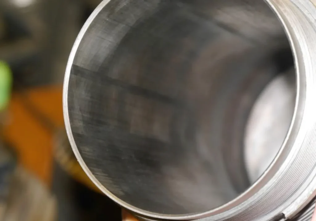
For standard single-rod piston-type hydraulic cylinders, assuming the same supply pressure and disregarding back pressure and friction, the larger the bore diameter, the greater the theoretical extension thrust. However, the bore diameter alone does not represent the hydraulic cylinder’s load-bearing capacity or rated pressure; you must also verify the rod diameter, structure and permissible working pressure.
When confirming the bore diameter, it is advisable to first consult the relevant drawings or specification tables for the model. During maintenance, once safe disassembly has been completed, you may use a suitable internal diameter gauge to measure the working bore. Do not directly use the metal outer diameter of the removed piston as a substitute for the precise bore diameter, as a design clearance is usually required between the piston and the cylinder barrel.
② Bore Diameter vs. Barrel Outside Diameter
The bore diameter measures the interior of the cylinder barrel, whilst the outside diameter measures the external contour; the difference between the two is the wall thickness on both sides. The bore diameter is primarily used to determine the piston’s pressure-bearing area; the outside diameter relates to the installation space and, together with factors such as wall thickness and material, influences the cylinder barrel’s pressure-bearing design.
For circular cylinders with concentric inner and outer diameters, uniform wall thickness and no liners, the following formula can be used: bore diameter = cylinder outer diameter − 2 × wall thickness. For example, assuming an outer diameter of 80 mm and a wall thickness of 8.5 mm on one side, the bore diameter is 80 − 2 × 8.5 = 63 mm. This is merely an illustrative example of the dimensional relationship and does not represent the actual structure of any specific product.
This method assumes that the wall thickness is accurately known. Measuring only the outer diameter does not allow for a reliable determination of the bore diameter. Different cylinders may have varying wall thicknesses, and paint, outer casings or localised thickening may also affect external measurements. If you are unsure of the structure and wall thickness, you should confirm these details via drawings or with the manufacturer; do not order based on specifications that appear similar at first glance.
③ Bore Diameter vs. Piston Rod Diameter
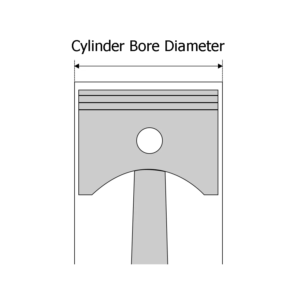
The piston rod is the component connected to the piston that transmits thrust and pulling forces outwards; the rod diameter refers to its diameter. Taking the example of a ‘bore diameter of 63 mm and a rod diameter of 40 mm’, 63 mm corresponds to the cylinder bore, whilst 40 mm corresponds to the piston rod. The shiny rod you see on the outside, even if it is easy to measure, cannot be used to determine the bore diameter.
For standard double-acting single-rod hydraulic cylinders, the full piston area is utilised on the extension side; on the retraction side, however, the cross-sectional area occupied by the piston rod must be deducted, with the remaining portion referred to as the effective annular area.
Therefore, assuming the cylinder bore and supply pressure remain constant, and disregarding back pressure and friction, increasing the piston rod diameter will not increase the theoretical extension thrust; rather, it will reduce the theoretical retraction pull force. The rod diameter affects both the strength of the piston rod and its buckling resistance, that is, its ability to resist compressive bending instability. When requesting a quotation or replacing a hydraulic cylinder, it is advisable to clearly specify ‘cylinder bore × rod diameter × stroke’, along with the units and definitions of each parameter.
Why Does Bore Size Determine Cylinder Force?
The bore diameter determines the area of the piston subjected to pressure, thereby influencing the force that a hydraulic cylinder can generate. At the same pressure, the larger the area subjected to pressure, the greater the theoretical thrust. You can think of pressure as the force exerted per unit area: when the same pressure acts on a larger piston area, the total thrust increases. However, the actual output is also affected by return line back pressure, friction and pressure drop in the supply line.
1. Convert Bore Diameter to Piston Area
Before calculating the thrust, you must first convert the bore diameter into piston area. For a circular bore, the formula is: piston area = π × bore diameter² ÷ 4. Here, π is approximately equal to 3.1416, and ‘bore diameter²’ refers to the bore diameter multiplied by itself. The inner diameter of the cylinder barrel should be used; the outer diameter of the cylinder barrel or the piston rod diameter must not be used as a substitute.
Assuming the bore diameter is 63 mm, the piston area is π × 63² ÷ 4 ≈ 3,117.2 mm². This area represents the effective pressure-bearing area on the rodless chamber side of a standard single-rod hydraulic cylinder. The “rodless chamber” refers to the oil chamber on the side of the cylinder through which the piston rod does not pass.
The area is proportional to the square of the bore diameter, not to the bore diameter itself. For example, if the bore diameter increases by 20 per cent, the area becomes 1.2² times the original, or 1.44 times the original. Under conditions of constant pressure and negligible losses, the theoretical extension thrust therefore increases by 44 per cent.
2. Calculating Extension Force from Pressure and Area
For a standard single-rod hydraulic cylinder, where oil enters the rodless chamber and back pressure in the return line can be neglected, the theoretical extension thrust = pressure in the rodless chamber × piston area. Units must be standardised in the calculation: pressure is expressed in MPa, area in mm², and the result is in N, as 1 MPa = 1 N/mm².
Continuing with the previous assumptions, if the pressure in the rodless chamber is 16 MPa, the theoretical thrust is 16 × 3,117.2 ≈ 49,876 N, or approximately 49.9 kN. Here, kN stands for kilonewtons, where 1 kN equals 1,000 N. You must also distinguish between actual operating pressure and rated pressure. Rated pressure indicates the pressure rating for which the product is authorised for use. When selecting a cylinder, the pressure available at the cylinder inlet during load operation should be used.
3. Account for Friction, Pressure Loss and Safety Margin
Pressure drops occur as hydraulic oil passes through valves, pipework and fittings; consequently, the pump outlet pressure may be higher than the cylinder inlet pressure. Back pressure may also be present on the return side, i.e. pressure that impedes the return of fluid. Furthermore, friction at seals and guide points consumes a portion of the driving force; particular attention should be paid to frictional resistance during start-up.
For the extension stroke, the net hydraulic thrust, taking into account the pressures in both chambers, is: pressure in the rodless chamber × piston area − pressure in the rod chamber × annular area. The annular area is the pressurised area remaining after deducting the cross-sectional area of the piston rod. Under conditions of approximately constant velocity, and disregarding the inertia of moving parts, internal friction must also be deducted to estimate the available thrust at the rod end. When calculating using the actual pressures in both chambers, do not deduct line losses again, as these are already reflected in the pressure readings.
4. Checking the Retract Force Using the Annular Area
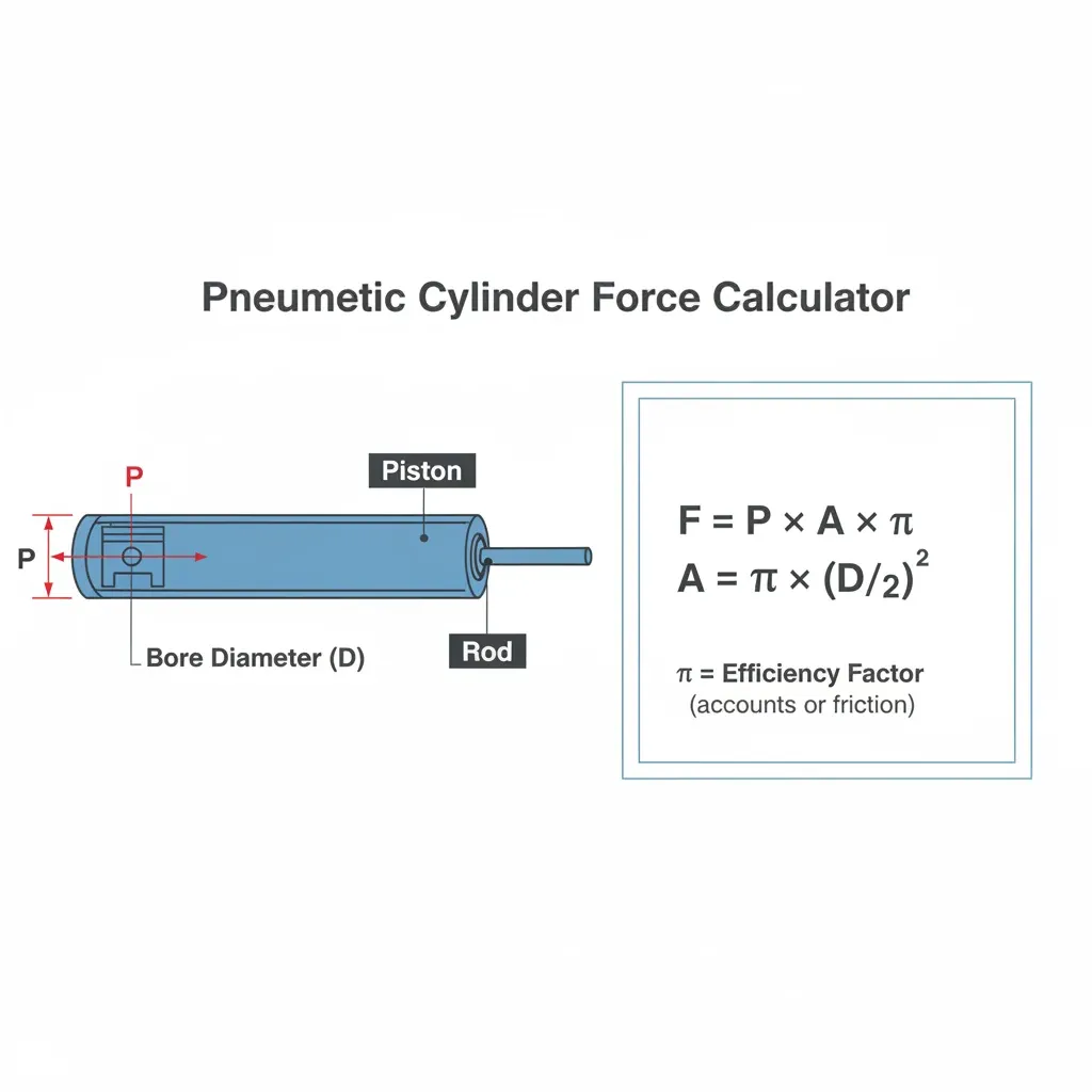
When a standard double-acting single-rod hydraulic cylinder retracts, hydraulic fluid enters the rod chamber. As the piston rod occupies part of the area, the effective pressure area during retraction is smaller. The formula for this is: Annular area = π × (cylinder bore² − rod diameter²) ÷ 4.
Assuming the cylinder bore remains at 63 mm and the rod diameter is 40 mm, the annular area is approximately 1,860.6 mm². Assuming the pressure in the rod chamber is 16 MPa, and neglecting both back pressure in the non-rod chamber and friction, the theoretical retraction force is 16 × 1,860.6 ≈ 29,770 N, or approximately 29.8 kN. Therefore, for the same cylinder operating at the same supply pressure, the retraction force is typically less than the extension thrust. If the retraction side needs to pull a heavier load, you must verify the retracting force separately. When there is return line back pressure, the net hydraulic retracting force is: rod chamber pressure × annular area − non-rod chamber pressure × piston area. It should also be noted that, for the same cylinder bore, a thicker piston rod reduces the annular area, thereby lowering the theoretical retracting force at the same pressure.
How Does Bore Size Affect Cylinder Speed and Oil Demand?
For the same stroke length, the larger the bore diameter, the more oil is required for the hydraulic cylinder to complete the extension stroke; with the same actual oil flow rate, the extension speed will be slower. Therefore, if you increase the bore diameter to improve thrust, you will also need to re-evaluate the cycle time and oil supply capacity. A larger bore diameter does not automatically result in faster operation.
Larger Bore Means More Oil per Unit of Travel
For every distance the piston moves, the inlet side must be filled with a corresponding volume of oil. For the extension stroke of a standard single-rod hydraulic cylinder, the required oil volume = total piston area × distance travelled. The piston area is determined by the bore diameter; therefore, for the same stroke, the oil volume required is proportional to the square of the bore diameter.
For example, assuming a stroke of 500 mm, when the bore diameter is 63 mm, the theoretical oil volume required for the rodless chamber to complete one full extension stroke is approximately 1.56 L; when the bore diameter is increased to 80 mm, this rises to approximately 2.51 L, an increase of about 61 per cent. This calculation is based on the change in volume caused by the piston’s movement, not the total oil capacity of the entire hydraulic cylinder and piping.
You also need to distinguish between ‘oil consumption’ and ‘oil usage’. During normal operation, hydraulic oil circulates within the system; whilst it enters one chamber, it is usually being discharged from the other. It is not consumed in the same way as fuel, where it is used up with every cycle.
Flow Rate Divided by Area Determines Speed
Flow rate is the volume of fluid passing through per unit of time, commonly measured in L/min. Assuming no leakage or fluid compression, and under conditions of stable motion, piston speed = actual flow rate entering the chamber ÷ effective pressurised area of that chamber. You can think of it this way: when the same amount of fluid is supplied per second, the larger the piston area, the shorter the distance it travels per second.
If the flow rate is given in L/min and the area in mm², the calculation can be performed directly: speed (mm/s) = flow rate × 1,000,000 ÷ (60 × effective area). Assuming the actual flow rate entering the rodless chamber is 20 L/min, the theoretical extension speed for a 63 mm bore diameter is approximately 107 mm/s, whilst for an 80 mm bore diameter it is approximately 66 mm/s. The theoretical time required to complete a 500 mm stroke is approximately 4.68 seconds and 7.54 seconds respectively, excluding start-up, deceleration and cushioning times.
The above comparison applies to standard oil supply configurations. During retraction, the annular area—calculated after deducting the cross-sectional area of the piston rod—must be used; consequently, the same standard single-rod hydraulic cylinder will typically retract faster when the oil supply flow rates in both directions are equal. Regenerative circuits return the return oil to the supply side, whilst multi-stage telescopic cylinders also switch their effective area; therefore, the same area and pump flow rate cannot be directly applied to calculate the entire process.
Bore Size, Cycle Time, Pump Flow, and Reservoir Capacity
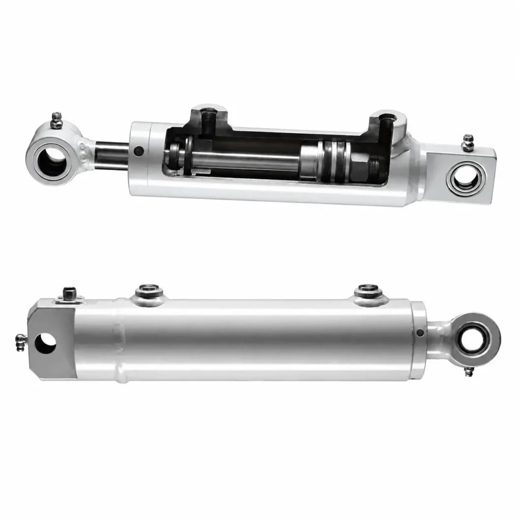
When selecting the cylinder bore diameter, you should specify both the required thrust and the operating time. The theoretical time required to complete one stroke is: Time (seconds) = Inlet volume (L) ÷ Flow rate (L/min) × 60. Continuing with the previous example, if you wish an 80 mm cylinder to complete a 500 mm extension within approximately 4.68 seconds, the actual inflow rate would need to be increased from 20 L/min to approximately 32.3 L/min. These are calculated values based on assumptions and do not represent actual product test data.
When selecting a pump, one must consider the actual flow rate it can deliver at the target operating pressure, whilst taking into account flow division when other actuators are operating simultaneously. Valves, ports and piping must also be capable of handling the required flow rate. For standard single-rod cylinders, the return flow rate from the rodless chamber during retraction may exceed the inflow rate to the rod chamber; therefore, the return flow path must also be verified.
The reservoir capacity cannot be directly equated to the oil supply required for a single extension stroke, nor can a fixed multiplier be applied based solely on the pump’s flow rate. For a standard double-acting single-rod cylinder with both chambers filled and the return flow directed back to the reservoir, where oil enters on one side and returns on the other during extension, the net reduction in reservoir oil volume is theoretically equal to ‘piston rod cross-sectional area × extension distance’. For single-acting cylinders and other circuits, calculations must be based on the actual direction of fluid flow. When determining the reservoir capacity, you must also account for the maximum change in oil level caused by the combined operation of all actuators, the minimum submersion requirement for the suction port, space for thermal expansion, and requirements for heat dissipation and air separation. The reservoir must maintain a sufficient oil level under maximum supply conditions whilst also allowing space for fluid return.
How Do You Measure Hydraulic Cylinder Bore?
The most direct method of measuring the bore diameter of a hydraulic cylinder is to measure the working bore of the cylinder barrel using an internal diameter gauge after it has been safely dismantled. If the hydraulic cylinder is still mounted on the equipment, the specifications should first be confirmed based on the model, drawings or manufacturer’s documentation. The piston’s outer diameter can be used for cross-checking, but cannot be taken directly as the precise bore diameter; measuring only the outer diameter of the cylinder barrel is also insufficient to determine the inner diameter.
1. Direct Measurement on a Disassembled Cylinder
Prior to disassembly, power must be isolated and the load securely supported in accordance with the equipment procedures, and it must be confirmed that the relevant oil chambers have been depressurised. Disassembly should be carried out by qualified personnel. After removing the piston assembly, clean the bore of the cylinder barrel to prevent oil residue, particles and burrs from affecting the reading; do not grind the inner wall arbitrarily for the sake of convenience.
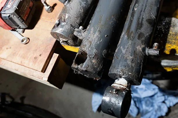
Calipers may be used as a preliminary tool to confirm approximate dimensions; however, when assessing dimensional tolerances or wear, an internal micrometre or internal gauge with appropriate accuracy and range should be used. Internal gauges are typically used for comparative measurements, requiring the reference dimension to be set first using standard ring gauges or a suitable reference device, followed by the reading of the deviation of the bore relative to the reference value. Mitutoyo Internal Measurement Guide
The measurement point should be located within the working bore where the piston actually moves, avoiding the inlet chamfer, threads and seal installation grooves. The measuring instrument must be correctly centred, and valid readings taken in accordance with its operating instructions. Do not take a single measurement at the cylinder end and use the result as the dimension for the entire cylinder barrel.
2. Measuring Piston Diameter as a Cross-Check
The piston diameter can help you verify the cylinder bore specification; however, in standard hydraulic cylinders, there is usually a design clearance between the metal body of the piston and the cylinder barrel. Seals are responsible for limiting leakage, whilst guide rings or wear rings assist with support and guidance. Therefore, the outer diameter of the metal piston body is not usually equal to the actual internal diameter of the cylinder barrel; the difference between the two should be determined by consulting the relevant design specifications and cannot be calculated by uniformly adding a fixed value.
When measuring, distinguish between the piston body, seals and guide rings, and prioritise measuring the metal reference surface specified in the drawings. Soft seals are prone to deformation and may change dimensions after removal; they are therefore unsuitable for accurately deriving the cylinder bore diameter. If there is no intact metal measuring surface, verify the dimensions using the part number or the manufacturer’s drawings; do not attempt to deduce the cylinder bore diameter solely from the dimensions of the seal grooves.
This inspection is suitable for identifying specifications or detecting obvious mismatches. For example, if there is an abnormal discrepancy between the measurement results of the cylinder barrel and the piston, you should check whether the parts are a matched set, whether the measurement positions are correct, and whether there is any wear, rather than immediately concluding that the cylinder barrel has been machined incorrectly.
3. Estimating Bore Without Disassembly
When disassembly is not possible, prioritise locating the relevant data or original drawings corresponding to the model number and serial number on the nameplate. The numbers in the model number do not necessarily directly represent the bore diameter; this should be confirmed according to the manufacturer’s coding rules. If you need to enquire with the supplier, you can provide photographs of the nameplate, the cylinder block and the connecting parts, as well as reliably measured external dimensions.
For cylindrical cylinders with concentric inner and outer diameters, uniform wall thickness and no lining, where the wall thickness is known accurately, the following formula may be used: Cylinder bore = Cylinder outer diameter − 2 × wall thickness on one side. For example, assuming an outer diameter of 80 mm and a wall thickness of 8.5 mm on one side, the estimated bore diameter is 80 − 2 × 8.5 = 63 mm. This is merely a calculation example and does not represent actual product measurements.
If the wall thickness is unknown, the bore diameter cannot be reliably estimated based on the external diameter alone. Paint, outer coatings, localised thickening or linings may also render the estimate invalid. This method is suitable for preliminary identification of specifications; it cannot replace precise measurement of the working bore, nor should it be used to determine whether the bore is worn or out of round.
4. Identifying Wear, Taper or Out-of-Round Conditions
Wear may cause localised enlargement of the bore; taper refers to the bore gradually widening or narrowing along its length; whilst out-of-roundness means that a given cross-section no longer retains its ideal circular shape. All of these conditions may affect sealing and guidance; therefore, you should compare multiple locations rather than relying solely on an average bore diameter.
As a preliminary inspection, you may select one cross-section each from the front, middle and rear sections of the piston’s working area, measuring each cross-section along at least two mutually perpendicular directions to obtain at least 6 readings. Variations in the same direction at different axial positions may indicate taper or localised wear; differences in the same cross-section in different directions may indicate ovality. Readings taken in two directions alone do not fully prove that the roundness meets specifications; for precision acceptance testing, more comprehensive inspection methods should be adopted in accordance with the drawing requirements.
At the same time, the inner wall should be inspected for scoring, corrosion and localised grooves. A pass in diameter measurement does not necessarily mean that the surface condition is suitable for continued use.
How Do You Calculate the Required Bore Size?
To calculate the required cylinder bore diameter, you should first determine the maximum thrust or pull force that the hydraulic cylinder needs to provide, then calculate the effective cross-sectional area using the actual available pressure at the cylinder port, and finally convert this to a diameter. Once the theoretical minimum value has been obtained, you must also take into account friction, back pressure and design margins before selecting the appropriate product specification. For standard single-rod hydraulic cylinders, the effective cross-sectional areas used during extension and retraction differ, so both directions must be verified separately.
① Define Maximum Push or Pull Load
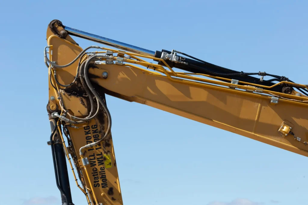
Firstly, you need to determine the maximum load the hydraulic cylinder will bear throughout the entire working cycle, rather than simply considering the average value during normal operation. In addition to the weight of the workpiece, you should also take into account friction in the guide rails, machining resistance, the force required for acceleration, and variations in force caused by changes in the connecting rod angle. For tilting or lifting mechanisms, the most difficult position to move may be at the start of the cycle, or it may occur at an intermediate position.
If the hydraulic cylinder lifts the load directly vertically, static gravity can be estimated using the formula Force = Mass × 9.81, where mass is in kg and force is in N. However, this is merely a base load and cannot replace a complete structural stress analysis. If the equipment requires both pushing and pulling, the maximum thrust and maximum pull force should be recorded separately; avoid using the extension thrust to judge the retraction capacity.
② Determine Available Working Pressure at the Cylinder
When calculating the cylinder bore diameter, use the actual pressure available at the hydraulic cylinder’s inlet during load operation. Pressure may drop as the pump’s outlet pressure passes through valves, pipework and fittings; therefore, the pump’s maximum pressure or the cylinder’s rated pressure must not be substituted directly. The rated pressure indicates the pressure rating for which the product is authorised for use; it does not guarantee that this value will be achieved during actual operation.
You must also confirm the return line back pressure, i.e. the pressure that remains on the discharge side. Back pressure counteracts part of the driving force and must not be ignored, particularly in return line throttling or load control circuits. Existing equipment can measure the pressure in both chambers under specified operating conditions; for new designs, this should be estimated based on the target flow rate and component pressure drops, and verified during commissioning.
③ Calculate the Minimum Theoretical Bore
Assuming friction is negligible and return back pressure is negligible, the following formula can be used for a standard single-rod hydraulic cylinder in the extended position: Required piston area = Required thrust ÷ Available pressure. Then calculate Minimum theoretical bore = √[4 × Required thrust ÷ (π × Available pressure)]. Here, √ denotes the square root, and π is approximately 3.1416. Thrust is expressed in N and pressure in MPa; the calculated bore diameter is given in mm. Enerpac Explanation of the Relationship between Pressure, Area and Force
For example, assuming a required thrust of 40 kN (i.e. 40,000 N) and an available pressure of 16 MPa, the required area is 40,000 ÷ 16 = 2,500 mm², and the minimum theoretical cylinder bore diameter is approximately 56.4 mm. This result does not account for friction or design margins and cannot be used directly as the final order specification.
If selecting a cylinder based on retraction force, the rod diameter must also be known. Under the same simplified conditions, the formula is: Minimum theoretical cylinder bore = √[rod diameter² + 4 × required tensile force ÷ (π × available pressure)]. This is because retraction utilises the annular area, i.e. the total piston area minus the cross-sectional area of the piston rod. When the rod diameter has not yet been determined, a candidate rod diameter must first be selected, followed by iterative verification of the cylinder bore and tensile force.
④ Apply Load and Pressure Margins
The theoretical minimum cylinder bore diameter merely indicates the minimum required under ideal conditions; it does not guarantee sufficient margin under actual operating conditions. You should clarify which factors are already included in the maximum load, and then allow a reasonable margin for unaccounted-for load variations, friction and pressure fluctuations, to avoid duplicate calculations. The margin should be determined based on application requirements and the manufacturer’s recommendations; it cannot be uniformly specified as a fixed percentage.
For demonstration purposes only, assume a 20 per cent force margin is added to the previous 40 kN requirement, and that the reliable operating pressure is calculated as 14 MPa, whilst still assuming that back pressure is negligible. The design force would then be 40 × 1.2 = 48 kN, corresponding to a cylinder bore diameter of approximately 66.1 mm. Note that both 20 per cent and 14 MPa are assumptions made for this example and do not constitute general selection criteria.
If back pressure cannot be ignored, calculations should be performed separately for each chamber. The net hydraulic thrust during extension is pressure in the rodless chamber × total piston area − pressure in the rod chamber × annular area, after which internal friction must be taken into account. One cannot simply subtract the pressures in the two chambers and multiply the result by the total piston area, as the effective areas on either side of a standard single-rod cylinder differ.
⑤ Select the Next Suitable Standard Bore
Once the required bore diameter for the design has been determined, consult the specifications of the target product range and select a bore diameter that is no smaller than the calculated requirement and meets all other conditions. Do not round down the calculated value, nor assume that all manufacturers have the same standard dimensions. After changing the rod diameter, the retraction force should also be re-checked.
For example, suppose a series offers two bore diameters within this range—63 mm and 80 mm—and the calculated requirement is 66.1 mm. In this case, 63 mm is insufficient, so 80 mm should be further evaluated. Calculated at 14 MPa, disregarding back pressure and friction, the theoretical thrust for a 63 mm bore diameter is approximately 43.6 kN, which is lower than the 48 kN design force in this example; the thrust for an 80 mm bore diameter is approximately 70.4 kN.
Worked Hydraulic Cylinder Bore-Sizing Example
The following hypothetical example illustrates: how to select candidate cylinder bore diameters based on load and pressure, and then verify the tensile force, speed and structural load-bearing capacity. This example uses a standard double-acting single-rod hydraulic cylinder with a maximum required working thrust of 40 kN. For demonstration purposes only, a 20 per cent force margin has been added, resulting in a design thrust of 48 kN; the design tensile force during retraction is taken as 30 kN.
Assume that the minimum reliable supply pressure in both directions of movement is 14 MPa; return line back pressure is negligible, and the design forces already incorporate the friction and load margins assumed in this example. The stroke is 500 mm, with target extension and retraction speeds of 100 mm/s. The figures below are all calculation assumptions and do not represent actual test results for GY hydraulic products; furthermore, the 20 per cent margin is not a universally recommended value.
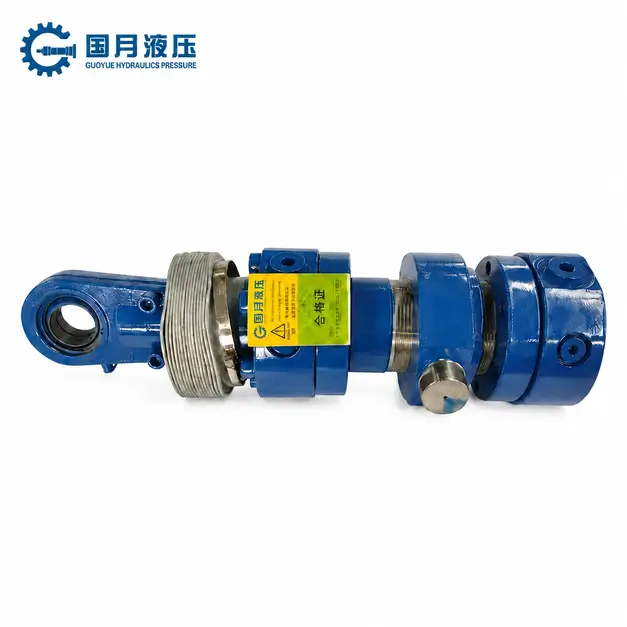
Calculate Required Piston Area
First, divide the design thrust by the available pressure to calculate the required piston area: Required area = 48,000 ÷ 14 ≈ 3,428.6 mm². Here, 48 kN is converted to 48,000 N; as 1 MPa equals 1 N/mm², the result is directly expressed in mm².
This area corresponds to the effective pressurised area required in the rodless chamber when the hydraulic cylinder is extended. You should use the pressure that is reliably available during load operation, rather than the pump’s maximum pressure. If there is significant actual return oil back pressure, the counteracting force generated by the pressure on the opposite side must be taken into account; the simplified calculation used in this example cannot be applied in such cases.
Convert Area to Bore Diameter
The area of a circular piston can be converted to the cylinder bore diameter: Bore diameter = √(4 × piston area ÷ π). Substituting 3,428.6 mm² yields √(4 × 3,428.6 ÷ π) ≈ 66.1 mm. Here, √ denotes the square root.
Assuming the target product range offers bore diameters of 63 mm and 80 mm within this range, you should first evaluate the 80 mm option. As 63 mm is less than the 66.1 mm required in this example, it cannot be rounded down. The piston area for an 80 mm bore is approximately 5,026.5 mm²; at 14 MPa, the theoretical extension thrust is approximately 14 × 5,026.5 ÷ 1,000 = 70.4 kN, which exceeds the 48 kN design requirement for this example.
The 80 mm bore is currently only a candidate; it cannot yet be confirmed that the entire hydraulic cylinder is suitable. Next, a 50 mm solid piston rod is provisionally selected to check the retract force, flow rate requirements and compressive stability.
Check Retract Force and Target Speed
For retraction, the annular area should be used, which is the total piston area minus the cross-sectional area of the piston rod. For a cylinder bore of 80 mm and a rod diameter of 50 mm, the annular area = π × (80² − 50²) ÷ 4 ≈ 3,063.1 mm². At 14 MPa, assuming no back pressure, the theoretical retract force is approximately 42.9 kN, which exceeds the 30 kN retract design requirement in this example.
The speed depends on the actual inflow rate and the effective area. When using mm² and mm/s, the formula is: Required flow rate (L/min) = effective area × velocity × 60 ÷ 1,000,000. To achieve 100 mm/s, extension requires approximately 30.2 L/min, whilst retraction requires approximately 18.4 L/min. As the cross-sectional areas differ in the two directions, the flow rates must be controlled separately to maintain the same speed. Enerpac Speed Calculation Notes
Calculated at a constant speed, a single stroke of 500 mm takes 500 ÷ 100 = 5 seconds. This does not include acceleration, deceleration, direction changes or dwell time. If the existing system can only supply 20 L/min to the rodless chamber, the theoretical extension speed would be only approximately 66 mm/s, taking approximately 7.54 seconds for a single stroke. Whilst the thrust would be sufficient in this case, the speed would not meet the target; the oil supply configuration should therefore be adjusted or the dimensions reassessed.
Verify Rod Buckling and Mounting Capacity
Buckling is a phenomenon whereby a piston rod becomes unstable and bends sideways under compressive load. When carrying out checks, one must not merely compare the normal operating load; the maximum compressive force that the system may exert must also be taken into account. Assuming that the maximum possible cylinder port pressure in this example is 16 MPa, and that there are no additional impacts or external pressurisation, the theoretical thrust at full extension during a stall condition can reach 16 × 5,026.5 ÷ 1,000 ≈ 80.4 kN.
For the purposes of demonstrating a preliminary buckling analysis, let us further assume that the effective buckling length corresponding to the installation and support conditions is 1,500 mm. The effective buckling length is the calculated length taking into account end constraints and cannot be directly substituted with the 500 mm stroke in this example. For a 50 mm solid steel member to which the Euler elastic buckling model applies, taking a modulus of elasticity of 210,000 N/mm², the calculated theoretical critical buckling load is approximately 282.6 kN. If a safety factor of 3 is assumed for this example, the preliminary screening permissible load is 282.6 ÷ 3 = 94.2 kN, which is higher than 80.4 kN.
This result merely indicates that the assumed compression member model passes the preliminary screening. The actual hydraulic cylinder must also be verified in accordance with the manufacturer’s methods regarding the overall structure, installation method and guidance conditions; this figure must not be taken directly as the product’s rated load-bearing capacity.
Mounting components also require separate verification. In this example, a theoretical retraction tensile force of approximately 49.0 kN may also be generated at 16 MPa; therefore, the pins, fork ears, rod-end threads, brackets and their connection points should be checked against the maximum loads in the relevant directions and the applicable design requirements.
Which Other Specifications Must Match the Bore?
Once the cylinder bore diameter has been determined, you must also match the rod diameter, stroke, compressive load capacity, pressure rating, porting and cushioning, as well as the sealing and cylinder bore surface requirements. The bore diameter primarily determines the piston’s compressive area; however, hydraulic cylinders with the same bore diameter may have different tensile forces, speeds, installation constraints and service lives, so interchangeability cannot be judged solely on the basis of bore diameter.
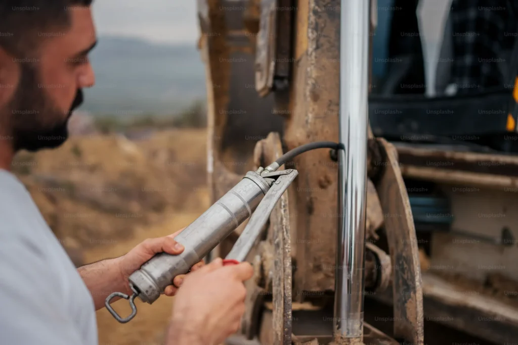
a. Rod Diameter and Area Ratio
The rod diameter affects the strength of the piston rod and also determines the remaining pressurised area on the retraction side. For a standard single-rod hydraulic cylinder, the annular area = total piston area − cross-sectional area of the piston rod. For the same bore diameter, a thicker piston rod reduces the annular area; therefore, at the same supply pressure—and disregarding back pressure and friction—the retraction force will be reduced.
The area ratio is used to describe the relationship between the compressed areas on both sides. The definition used here is: area ratio = total piston area ÷ annular area. For example, assuming a bore diameter of 80 mm and a rod diameter of 50 mm, the two areas are approximately 5,026.5 mm² and 3,063.1 mm² respectively, giving an area ratio of approximately 1.64. Under ideal conditions where the oil flow rate is the same in both directions, the retraction speed is approximately 1.64 times the extension speed; at the same supply pressure, the theoretical retraction force is approximately 61 per cent of the extension thrust.
You should verify the required force, speed and the load-bearing capacity of the rod simultaneously; you must not simply seek a thicker piston rod. When reviewing data from different suppliers, you should also first confirm the definition of the ‘area ratio’ to avoid confusing it with the ratio of the rod diameter to the cylinder bore diameter.
b. Stroke and Column-Load Capacity
Column load capacity here refers to the compressive load borne by the hydraulic cylinder along its axis. When the stroke is long and the piston rod is extended significantly, buckling may occur; that is, the rod may buckle laterally under pressure and become unstable. A larger cylinder bore can generate greater thrust, but this does not automatically increase the buckling resistance of the same piston rod.
Therefore, you should provide the manufacturer with the cylinder bore, rod diameter, maximum compressed extension position, mounting method and external guidance for verification. When checking loads, you must also consider the thrust that the system may exert if the workpiece becomes jammed, rather than just the normal operating load. The calculated length should be determined based on the actual installation configuration and must not be directly substituted with the stroke.
For applications where the rod is constantly under tension, buckling is not usually a major limiting factor. However, if the operating cycle includes pushing, directional change impacts or external compressive loads, the relevant positions must still be checked. The manufacturer has already included a safety factor in the permissible load; this should be used in accordance with their instructions to avoid duplicate reductions or mistaking it for the theoretical buckling load.
c. Working and Proof Pressure
Working pressure is the pressure actually borne by the hydraulic cylinder during operation; the rated working pressure is the permissible operating rating specified by the manufacturer; whilst the hydrostatic test pressure is the test pressure used to verify pressure resistance under specified conditions. Passing a hydrostatic test at a higher pressure does not imply that the hydraulic cylinder can operate continuously at that pressure.
When selecting a pressure rating, you must verify the overall capacity of the cylinder barrel, end caps, connection structures and seals; you must not rely solely on the cylinder bore diameter or wall thickness. You should also check for potential pressure peaks in both chambers. Under certain load control or sealed chamber operating conditions, localised pressure may exceed the pump discharge pressure.
When purchasing, it is advisable to explicitly request that the supplier specify the rated working pressure, burst test pressure, test conditions and acceptance criteria. Do not assume that all products are tested at the same test multiplier, nor should the burst test be regarded as proof of fatigue life, rod buckling or the strength of mounting components.
d. Port Size, Flow Velocity, and Cushioning
The ports should be matched to the target flow rate and the actual internal bore dimensions. As the cylinder bore increases, a higher flow rate is generally required if the same piston speed is to be maintained. The fact that the port threads fit does not necessarily mean that the internal bore can meet the flow requirements. An excessively small bore will increase local flow velocity and pressure drop, affecting speed and potentially increasing heat generation and return line back pressure.
The return flow rate should also be verified separately. Taking the previous example of an 80 mm cylinder bore and a 50 mm rod diameter, if 20 L/min is fed into the rod side during retraction—ignoring leakage and compression—the discharge rate from the non-rod side is approximately 20 × 1.64 = 32.8 L/min. Consequently, the adequacy of the return port, valves and pipework must not be assessed solely on the basis of 20 L/min.
Cushioning is a function that decelerates the piston as it approaches the end of its stroke; it must be verified based on the moving mass, velocity, direction and stopping process. A larger bore diameter or larger port size cannot substitute for a cushioning capacity verification. If the equipment utilises only a portion of the stroke and the stopping position does not enter the internal cushioning zone, additional deceleration measures are required.
e. Seal Size and Cylinder Bore Surface Finish
Seals must not only match the cylinder bore diameter but also the dimensions of the mounting groove, seal configuration, pressure, speed, temperature and hydraulic fluid. Seals specified for the same cylinder bore diameter are not necessarily interchangeable. You must also verify the seal cross-section, groove width, groove base diameter and permissible extrusion clearance. The extrusion clearance is the gap between components adjacent to the seal; if this is too large, the seal may be forced into the gap under pressure and become damaged.
The inner surface of the cylinder barrel must also be compatible with the seal material. A surface that is too rough may abrade the seal; conversely, a surface that is too smooth or lacks suitable oil-retaining texture may also impair lubrication. The Ra value in surface roughness indicates the average level of contour deviation, but a single Ra value alone cannot fully describe whether a surface is suitable for sealing.
Common Bore-Selection Mistakes
The most common mistake when selecting the bore diameter of a hydraulic cylinder is to consider only the theoretical thrust without also verifying the maximum load, the available pressure at the cylinder ports, the retraction force and the operating speed. The bore diameter is the working internal diameter of the cylinder barrel, which determines the area over which the piston is subjected to pressure. You need to ensure that this area is sufficient for the actual operating conditions, rather than simply choosing a larger bore diameter that ‘appears more powerful’.
Sizing for Average Rather Than Peak Load
The average load is no substitute for the peak load that the hydraulic cylinder must overcome. The peak load is the maximum force encountered during a working cycle; it may occur during start-up, acceleration, press-fitting, or when the connecting rod is at an unfavourable angle. If you select the cylinder bore size based solely on the average value during steady operation, the equipment may function normally for most of the stroke but come to a halt at a critical point.
You can examine the extension and retraction processes separately, recording the thrust or pull required at each position, whilst taking into account friction, acceleration and deceleration, and changes in the mechanical lever arm. It is also important to distinguish between the ‘peak load that must be overcome during normal operation’ and the ‘load resulting from a jam’. If the equipment is designed to stop when a workpiece becomes jammed, the cylinder bore should not be continuously increased in an attempt to force the workpiece past the obstruction. You need to confirm pressure-limiting and shutdown measures, and verify the maximum forces that the hydraulic cylinder and its mounting components can withstand in the event of a jam.
Using Pump Rating Instead of Available Cylinder Pressure
The rated pressure of a pump is not equivalent to the pressure actually available to the hydraulic cylinder during operation. The rated pressure indicates the pump’s pressure-bearing capacity under specified conditions; it does not mean that it will always deliver this pressure. As the fluid passes through valves, pipework and fittings, pressure drops occur—that is, pressure is lost during flow.
For example, suppose you base your calculations on a cylinder port pressure of 16 MPa, but at the target speed, only 14 MPa is actually achievable. Assuming the pressure-receiving area remains constant and disregarding return line back pressure and friction, the theoretical thrust will be 12.5 per cent lower than the original calculated value. This is sufficient to prevent a cylinder selected with a margin that was already tight from completing the required motion. When making an actual assessment, one should verify the pressure that the hydraulic cylinder can reliably achieve at the required flow rate.
Ignoring Pull Force and Backpressure
For standard single-rod hydraulic cylinders operating at the same supply pressure, the theoretical retraction pull force is typically less than the extension thrust. This is because the piston rod occupies part of the pressurised area in the rod chamber. The remaining annular area is the total piston area minus the cross-sectional area of the piston rod. Selecting a cylinder based solely on the extension thrust may result in the cylinder being able to push the workpiece in but failing to pull it out.
Return line backpressure must not be arbitrarily ignored either. Backpressure is the pressure that remains on the return side, and it offsets part of the driving force. For typical retraction conditions, the theoretical net pulling force = rod chamber pressure × annular area − non-rod chamber backpressure × total piston area. The actual available pulling force must also take into account internal friction within the hydraulic cylinder.
Taking a hypothetical cylinder bore of 80 mm and a rod diameter of 50 mm as an example, when the pressure in the rod chamber is 14 MPa, the theoretical pulling force—ignoring back pressure and friction—is approximately 42.9 kN. If the back pressure in the non-rod chamber is 2 MPa, the theoretical net pulling force drops to approximately 32.8 kN. Therefore, you should verify the loads and pressures in both chambers separately for each direction of movement. For double-acting cylinders, differential circuits or multi-stage hydraulic cylinders, calculations must be performed based on their respective effective areas and circuit configurations.
Oversizing the Bore Without Checking Cycle Speed
When the actual flow rate entering the hydraulic cylinder is constant, the larger the cylinder bore, the slower the extension speed. This is because, for every identical distance the piston moves, the larger the area under pressure, the more fluid is required to fill it. The fundamental relationship is: speed of movement = flow rate into the working chamber ÷ effective area of that chamber.
For example, assuming a stroke of 500 mm and a flow rate into the rodless chamber maintained at 20 L/min, whilst disregarding leakage, acceleration, deceleration and buffering times, increasing the bore diameter from 63 mm to 80 mm would result in the theoretical extension time increasing from approximately 4.68 seconds to 7.54 seconds. If you only consider the thrust, you may select a hydraulic cylinder that is capable of moving the load but fails to meet the production cycle time.
Increasing the cylinder bore may be a reasonable choice, but you should simultaneously recalculate the extension and retraction times, and verify the pump’s flow rate at the required pressure, as well as the flow capacity of the valves and piping. In particular, when multiple actuators operate simultaneously, the total flow rate of the pump is not equal to the flow rate allocated to this specific hydraulic cylinder.
Assuming Barrel OD Equals Bore
The barrel’s outside diameter must not be used as the bore diameter. The outside diameter includes the cylinder walls on both sides, whilst the effective area generating hydraulic thrust depends on the internal working diameter. Two hydraulic cylinders that appear to be the same thickness may have different bore diameters due to differences in wall thickness or internal structure.
Only when the cylinder barrel is concentric, has uniform wall thickness and lacks special structures such as liners can the geometric calculation ‘bore diameter = cylinder barrel outer diameter − 2 × wall thickness’ be applied. For example, assuming an outer diameter of 80 mm and a wall thickness of 8.5 mm on one side, the internal diameter is 63 mm. If the calculation is erroneously based on 80 mm, the theoretical thrust at the same pressure will be overestimated by approximately 61 per cent.
Frequently Asked Questions About Hydraulic Cylinder Bore
Does a Larger Bore Always Produce More Force?
Not necessarily. Only when the supply pressure is constant and the return back pressure and friction are negligible does a larger bore result in greater theoretical thrust. The bore is the working internal diameter of the cylinder barrel, which determines the area over which the piston is subjected to pressure. The basic relationship is: theoretical thrust = pressure × effective pressure area. According to this ideal relationship, if the bore diameter is doubled, both the area and the theoretical thrust will quadruple.
In actual operation, a hydraulic cylinder does not always deliver maximum thrust. Pressure varies with the load and the circuit conditions; therefore, a larger bore diameter may also be used to reduce the pressure required to move the same load. When comparing two hydraulic cylinders, you should check the actual pressure at the cylinder ports; if retraction is required to pull the load, you must also take into account the area occupied by the piston rod, as well as the offsetting effect of the pressure on the return side against the pulling force.
Does a Larger Bore Make a Cylinder Slower?
When the actual flow rate into the rodless chamber is the same and leakage is negligible, a larger bore will result in a slower extension speed. The rodless chamber is the side of the piston not connected to the piston rod. The larger the bore, the more fluid is required for the piston to travel the same distance; consequently, it moves more slowly at the same fluid supply rate. The calculation is as follows: speed = flow rate ÷ effective pressure area.
Taking an ideal calculation as an example, if the bore increases from 63 mm to 80 mm, the piston area increases by approximately 61 per cent, and the extension speed at the same flow rate will drop to approximately 62 per cent of the original. If the actual fluid flow rate were also increased by approximately 61 per cent, the original extension speed could theoretically be maintained. Therefore, when replacing a hydraulic cylinder with a larger bore, you should recalculate the cycle time and confirm that the pump, valves and piping can provide the required flow rate. The retraction speed must be calculated separately using the effective area after deducting the piston rod area.
Can Bore Size Be Determined From Rod Diameter?
The bore diameter cannot be accurately determined solely from the piston rod diameter, as there is no fixed one-to-one correspondence between the two. The same bore diameter can be configured with different rod diameters to meet requirements for tensile force, long-stroke stability or connection structures; conversely, the same rod diameter may be used in products with different bore diameters. A thicker piston rod does not directly indicate greater thrust in the hydraulic cylinder.
You may use the rod diameter as supplementary information for model identification, but do not place orders directly by reverse-calculating the bore diameter using a fixed ratio. Prioritise checking the nameplate model, manufacturer’s drawings or product catalogues. If this information is missing, a qualified person must further verify the internal dimensions after the equipment has been safely isolated. Measurements taken from the exposed piston rod can only confirm the rod diameter; they cannot confirm the cylinder bore diameter.
Are Hydraulic Cylinder Bore Sizes Standardised?
Some hydraulic cylinder series use standardised bore diameters, but there is no single set of dimensions applicable to all hydraulic cylinders. The market offers metric and imperial series, as well as custom bore diameters. Common sizes such as 40, 50, 63, 80 and 100 mm are standard metric specifications; however, to determine availability and compatible rod diameters, you must consult the relevant product series. Manufacturers’ catalogues typically list bore diameters, rod diameter options and applicable mounting dimensions separately. Refer to the Parker HMI series catalogue
A matching standard bore diameter does not mean that the entire hydraulic cylinder is directly interchangeable. For example, 2.5 inches in imperial is equivalent to 63.5 mm, but cannot be treated as a 63 mm specification. When replacing or purchasing a cylinder, you should verify the units, stroke, retracted installation length, rod end connection, porting and rated pressure; when ordering seals, you must also ensure they match the specific groove dimensions and seal configuration.
Choosing a Trusted Hydraulic Cylinder Manufacturer
From standard hydraulic cylinders to custom solutions, we help you improve equipment performance, delivery reliability, and batch consistency
Explore Rivmate Cases

Hey There, I'm Melody!
We are a hydraulic cylinder manufacturer. For over 20 years, we have focused on producing reliable hydraulic cylinders. Need a hydraulic cylinder solution? Feel free to contact us.