Home / Engine Cylinder vs. Hydraulic Cylinder in a Dump Truck
Engine Cylinder vs. Hydraulic Cylinder in a Dump Truck
- Author: GY Hydraulic
- 20+ Years of Manufacturing
The engine cylinders in a tipper lorry are responsible for generating engine power, whilst the hydraulic cylinders utilise the pressure of hydraulic oil to lift the tipper body. Although both are referred to as ‘cylinders’ in English, their functions and operating principles differ. The combustion gases within the engine cylinders push the pistons, which in turn transmit rotational power via the connecting rods and crankshaft; the lifting hydraulic cylinder converts hydraulic energy into linear thrust, allowing the tipper body to tilt for unloading.
In common diesel-powered tipper lorries, the engine also drives a hydraulic pump via the transmission to supply oil to the lifting system. Therefore, the two work in tandem but cannot be interchanged. If you are purchasing or replacing components for the tipper body, you need to confirm the specifications of the hydraulic cylinder, rather than the number of engine cylinders or the engine’s displacement.
Table of Contents
What Is the Difference Between an Engine Cylinder and a Hydraulic Cylinder?
An engine cylinder drives the piston through internal combustion, with the connecting rod and crankshaft converting this reciprocating motion into rotational power; a hydraulic cylinder, on the other hand, utilises the pressure of hydraulic oil to generate linear thrust or tensile force. In a fuel-powered tipper lorry, the former forms part of the engine’s internal structure, whilst the latter serves as the actuator for lifting the load bed. Although they both contribute to the vehicle’s operation, they perform different functions and cannot be interchanged.
a. An Engine Cylinder Produces Rotational Power Through Combustion
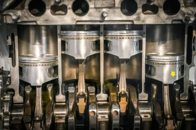
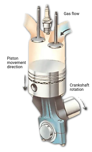
The engine cylinder is the working chamber where the piston performs reciprocating motion and participates in the combustion process to generate work. Taking a diesel engine as an example, air is compressed, causing its temperature to rise; the injected diesel then combusts, producing high-temperature, high-pressure gas that drives the piston. This process converts the chemical energy of the fuel into mechanical energy.
It is important to note that the piston within the cylinder itself performs linear reciprocating motion and does not directly produce rotational motion. The piston is connected to the crankshaft via a connecting rod; the crankshaft is the shaft that converts this reciprocating motion into rotational motion. The engine then drives the vehicle via the transmission system or provides power to other equipment.
Therefore, when you see the term ‘six-cylinder engine’, it refers to an engine with six cylinders inside, rather than a vehicle equipped with six hydraulic lifting cylinders. When purchasing engine-related parts, you must verify the engine model, serial number and corresponding part number; you cannot use the dimensions of a vehicle body lifting hydraulic cylinder as a basis for matching.
b. A Hydraulic Cylinder Converts Fluid Pressure Into Linear Force
A hydraulic cylinder is a device that utilises pressurised hydraulic fluid to drive internal moving parts, thereby generating an outward linear force. Conventional piston-type hydraulic cylinders transmit this force via a piston rod; telescopic hydraulic cylinders, on the other hand, extend through a set of multi-stage cylinder sections to achieve a longer stroke. In tipper lorries, the linear extension of the hydraulic cylinder, via mounting points or a lifting mechanism, causes the body to rotate about a pivot point and tilt for unloading.
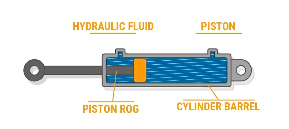
Hydraulic oil acts here as a medium for transmitting energy, not as a fuel for combustion. Neglecting pressure on the return side and friction, the theoretical thrust can be expressed as: Thrust = Working pressure × Effective pressure area. For example, assuming an effective area of 5,000 mm² and a working pressure of 16 MPa, the theoretical thrust is 80,000 N, or 80 kN. This is a calculation example illustrating the principle and cannot be directly converted into the vehicle’s permissible load capacity in tonnes, as the weight of the body, the centre of gravity of the cargo and the mounting angle all affect the required lifting force.
When selecting a lifting hydraulic cylinder, you should verify the load, operating pressure, stroke and mounting dimensions. The stroke is the distance the hydraulic cylinder travels from the retracted to the extended position. For multi-stage telescopic cylinders, you must also confirm the effective pressure area for each stage.
c. Why the Two Components Are Connected but Not Interchangeable
The connection between the two lies in energy transfer: the engine can power the hydraulic pump, which in turn supplies oil to the lifting hydraulic cylinder. In a typical tipper lorry configuration, engine power is transmitted via the drivetrain and a power take-off (PTO) to drive the hydraulic pump. A power take-off (PTO) is a device that draws mechanical power from the vehicle’s powertrain to drive auxiliary equipment. Control valves then regulate the direction and flow rate of the hydraulic fluid to raise or lower the body in a controlled manner.
This configuration is not applicable to all vehicles. Configurations utilising an electric motor to drive the hydraulic pump can also be used to raise the body via hydraulic cylinders. Therefore, hydraulic cylinders require a compatible hydraulic power supply system and do not necessarily need to be powered directly by a diesel engine. These two types of components are not interchangeable, as they differ in terms of structure, sealing methods, working fluid and output connections. When requesting a quotation, please specify whether you require engine internal components or a body-lifting hydraulic cylinder, and attach photographs of the nameplate and the installation location.
What Does an Engine Cylinder Do in a Dump Truck?
In diesel tipper lorries, the engine cylinders provide the working space for combustion and piston movement, helping the engine to convert the energy of the fuel into mechanical power. This power can either drive the wheels via the transmission system or be used to drive the hydraulic pump for the lifting system. The cylinders themselves do not extend to lift the body; it is the hydraulic cylinders that directly perform the lifting action.
Containing the Combustion Cycle
The engine cylinder, together with the piston and cylinder head, forms a space that contains the combustion gases. The piston is the component that moves back and forth within the cylinder, whilst the cylinder head seals the top of the cylinder. In a typical four-stroke diesel engine, each cylinder sequentially undergoes the intake, compression, power and exhaust strokes. As the air is compressed, its temperature rises; the injected diesel fuel ignites, and the resulting high-temperature, high-pressure gases then drive the piston to perform work.
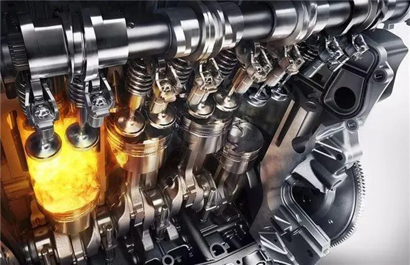
The term ‘four-stroke’ refers to the piston completing four single-stroke movements, corresponding to two revolutions of the crankshaft; it does not mean that the engine has four cylinders. The cylinder walls also serve to guide the piston’s movement, work in conjunction with the piston rings to maintain a seal, and transfer heat. Piston rings are annular components fitted around the periphery of the piston, designed to help seal the combustion gases and control the lubricating oil.
If the cylinder, piston rings or valves are not properly sealed, compression may be reduced, affecting starting and power output. However, one should not conclude that the cylinders are worn simply because the vehicle ‘lacks power’, as faults in the fuel supply, intake or turbocharging systems may also cause similar symptoms. During repairs, a diagnosis should be made in conjunction with fault diagnosis and the manufacturer’s specified testing methods.
Drive the Crankshaft and Vehicle Powertrain
Combustion gases first drive the piston in a linear motion, which in turn drives the crankshaft to rotate via the connecting rod. The connecting rod links the piston to the crankshaft; the crankshaft converts the reciprocating motion into rotational motion. Multiple cylinders alternate in performing work according to their designed sequence, enabling the engine to deliver continuous power.
In common mechanically driven tipper lorries, this power is transmitted to the wheels via the gearbox, drive shaft and drive axle. The gearbox alters the relationship between rotational speed and torque through different gears. Torque can be understood as the ‘twisting force’ that causes a shaft to rotate; therefore, when the vehicle is starting under heavy load or climbing a gradient, a suitable low gear is usually required to increase the driving force at the wheels.
When assessing whether a vehicle’s power is adequate, one should not focus solely on the number of cylinders. The engine’s torque and power at actual operating speeds, the gearbox ratios and the vehicle’s gross vehicle weight must all be taken into account. A six-cylinder engine is not necessarily better suited to a particular task than a four-cylinder engine, nor can a tipper lorry’s lifting capacity be directly judged by the number of cylinders.
Power Supply for Driving and Auxiliary Equipment
In addition to propelling the vehicle, the engine can also provide mechanical power to auxiliary equipment such as hydraulic pumps. A common method is to output power via a power take-off (PTO). A PTO is a device that draws power from the engine or the vehicle’s drivetrain to supply auxiliary equipment. When used for body lifting, it drives a hydraulic pump to supply oil, which is then used by the hydraulic system to control the movement of the lifting cylinders. The PTO and pump must be matched to the specific vehicle configuration, and installation space may also limit the choice of pump.
The engine’s maximum horsepower is not equivalent to the power permitted to be output by the PTO, nor is it equivalent to the lifting force of the hydraulic cylinders. When selecting a lifting system, you should verify the available power at the specified operating speed, the permitted torque of the PTO, the transmission ratio, as well as the speed and drive power required by the hydraulic pump. You must not select a hydraulic pump based solely on the maximum power stated on the engine nameplate.
This method of power transmission applies to configurations where the pump is driven by the engine. When using a separate electro-hydraulic power unit, the pump is driven by an electric motor, and the lifting action does not require power via the PTO path described above. Therefore, when assessing the relationship between the engine and the lifting system, you should first check the vehicle’s actual drive configuration.
What Does a Hydraulic Cylinder Do in a Dump Truck?
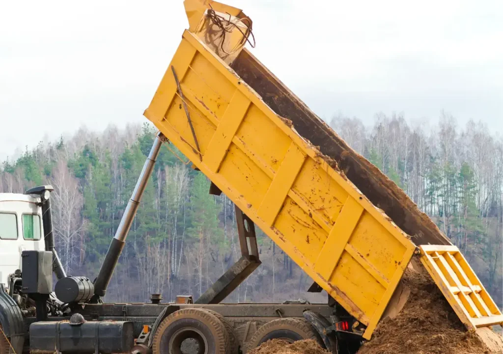
The hydraulic cylinders on a tipper lorry convert the pressure of the hydraulic fluid into linear thrust, lifting the tipper body via the lifting mechanism so that the load is unloaded by gravity. During lowering, common single-acting hydraulic cylinders retract under the weight of the tipper body, with the return speed controlled by a hydraulic valve; double-acting hydraulic cylinders, on the other hand, can actively retract using hydraulic pressure. Whether the lifting and lowering operations are carried out smoothly depends on the coordination between the hydraulic cylinders, control valves and the entire mechanical structure.
① Raising the Dump Body
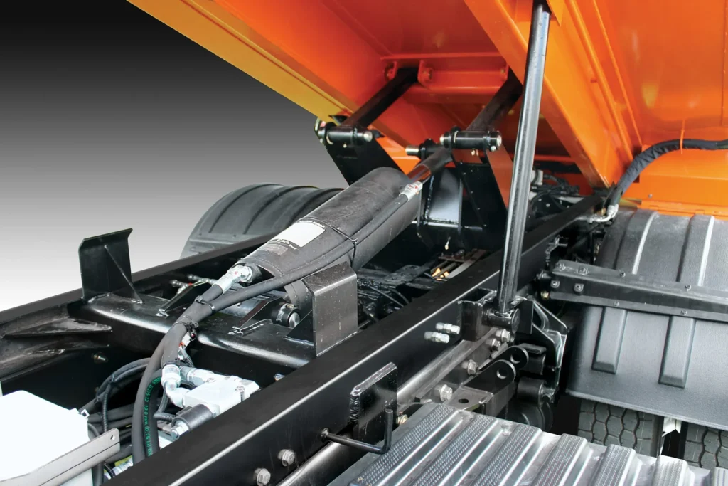
Once the hydraulic cylinder extends, it tilts the tipper body via mounting points or a linkage mechanism. In the case of common rear-dumping lorries, the body rotates about the rear pivot point, causing the front end to rise gradually. The hydraulic cylinder may be connected directly between the chassis and the body, or the thrust may be transmitted via a lifting mechanism mounted beneath the body.
When a long lifting stroke is required but installation space is limited, multi-stage telescopic hydraulic cylinders are often used. This type of hydraulic cylinder consists of nested cylinder sections; it is shorter when retracted but achieves a longer stroke when extended. The stroke is the distance travelled by the hydraulic cylinder from fully retracted to fully extended. It is not equivalent to the distance by which the front end of the body is raised; the relationship between the two is also influenced by the installation position and the body’s rotation trajectory.
When selecting a replacement hydraulic cylinder, you should verify the retracted installation length, effective stroke and required tipping angle simultaneously. A longer stroke does not necessarily mean it is more suitable: an excessively long stroke may cause mechanical interference or exceed the permissible lifting angle, whilst a stroke that is too short may prevent the body from reaching the required position. Selection should be based on the drawings of the body and lifting mechanism, rather than simply comparing the external appearance of the hydraulic cylinders.
② Control Lowering or Powered Retraction
Single-acting hydraulic cylinders typically operate on the principle of ‘hydraulic lifting, gravity lowering’, with the lowering speed primarily regulated by the control circuit. Single-acting refers to hydraulic pressure actively driving the cylinder in only one direction. During the lowering operation, the control valve opens the return oil passage, allowing the weight of the body to push the hydraulic cylinder back in, returning the hydraulic fluid to the reservoir. The hydraulic cylinder itself does not independently determine the lowering speed; factors such as load size, valve opening and return flow resistance all have an impact.
Double-acting hydraulic cylinders can receive pressurised oil in both the extension and retraction directions, and are therefore capable of providing an active retraction force. This capability may be useful when the mechanism is unable to begin retracting under its own weight from certain positions. However, whether a double-acting configuration is required should be determined by the design of the lifting mechanism. Muncie’s technical documentation also distinguishes between single-acting telescopic cylinders used in common tipper applications and special configurations requiring hydraulically assisted retraction. Refer to the Muncie Telescopic Hydraulic Cylinder Application Guide
When determining the retraction method, you should consult the hydraulic schematic and the hydraulic cylinder model; do not rely solely on the number of visible ports. If the body is lowering slowly, do not immediately assume the hydraulic cylinder is faulty; you should also check the return oil passages, the condition of the hydraulic fluid and whether the mechanism is jammed. When it is necessary to access the underside of a raised body for inspection, the mechanical supports specified by the manufacturer must be used; hydraulic pressure holding cannot replace maintenance supports.
③ Converting Hydraulic Pressure into Lifting Force
The lifting thrust of a hydraulic cylinder results from the hydraulic pressure acting on the effective pressure area. The effective pressure area is the area that actually contributes to the generation of driving force. When friction and pressure on the return side are neglected, the theoretical thrust can be estimated using the formula ‘thrust = pressure × effective pressure area’; for double-acting designs, the counteracting force generated by the pressure in the other chamber must also be deducted.
For example, assuming a working pressure of 16 MPa and an effective pressure area of 5,000 mm², the theoretical thrust is 16 × 5,000 = 80,000 N, or 80 kN. Here, 1 MPa equals 1 N/mm², so this set of units can be used directly for calculations. This is merely a hypothetical example to illustrate the principle; the actual available thrust will also be affected by factors such as friction and the actual pressure at the cylinder ports. A hydraulic cylinder thrust of 80 kN should not be directly interpreted as meaning that the vehicle can lift approximately 8 tonnes of cargo. The hydraulic cylinder must overcome the rotational force generated by the interaction between the vehicle body and the cargo at the pivot point; the installation angle, point of application and the centre of gravity of the cargo will all alter the required thrust.
How Does Power Travel From the Engine to the Dump Cylinder?
In common transmission-driven power-take-off (PTO) tipper lorries, the rotational power from the engine is transmitted via the transmission’s PTO gears and the power take-off unit to drive the hydraulic pump, and is then transferred to the lifting hydraulic cylinder via pressurised hydraulic fluid. ** The hydraulic cylinders convert hydraulic energy into linear thrust to lift the tipper body. The oil tank supplies the hydraulic fluid, the control valves determine the flow direction, and hoses and pipework connect the various components. This pathway facilitates the conversion from mechanical power to hydraulic power and ultimately to the lifting action.
Engine and Transmission
The engine outputs rotational power via the crankshaft. For power take-offs (PTOs) mounted on the gearbox, power is transmitted via designated PTO gears within the gearbox. A stationary vehicle does not mean the hydraulic pump cannot operate: provided the vehicle meets the PTO conditions for that model, the engine can supply power to the lifting system even when the wheels are not turning.
You must distinguish between driving gears and PTO operating modes. Whether the PTO can operate in neutral, whether the clutch needs to be engaged when connecting it, and the permissible engine speed all depend on the transmission and PTO configuration; you cannot simply adopt the operating procedures of another vehicle. Systems where power is drawn directly from the engine or where the pump is driven by an electric motor do not strictly follow the transmission-based PTO path described above.
Power Take-Off
The power take-off (PTO) is responsible for transferring mechanical power from the vehicle’s powertrain to the hydraulic pump. It typically transmits rotational motion via a gear train; the hydraulic pump may be mounted directly on the PTO or connected via a drive shaft. The PTO does not supply oil directly to the hydraulic cylinders.
The output speed of the PTO is not necessarily equal to the engine speed. Assuming a specific installation combination specified by the manufacturer has an output speed of 125 per cent of the engine speed, then when the engine is running at 1,200 rpm, the PTO output will be 1,500 rpm. Here, rpm denotes revolutions per minute. This is merely a calculation example; the actual ratio must be checked against the corresponding configuration, and the gear ratio within the PTO must not be directly equated with the speed ratio of the complete installed system.
When selecting a PTO, you should verify the gearbox compatibility, output rotation direction, speed and permissible torque. Torque is the ‘twisting force’ that rotates the drive shaft. Simply checking whether the interface fits may result in the pump rotating in the wrong direction, excessive speed, or the PTO being unable to withstand the required load.
Hydraulic Pump
A hydraulic pump converts the input mechanical power into hydraulic energy, drawing fluid from the reservoir and delivering it to the working circuit. The pump provides flow, whilst pressure is established in response to the load and circuit resistance. The rated pressure on the pump nameplate indicates the pressure capacity under specified conditions; it does not mean that the pump will always operate at this pressure.
For common fixed-displacement pumps—that is, pumps with a fixed theoretical oil delivery per revolution—flow rate primarily varies with rotational speed. Assuming a pump displacement of 40 cm³/rev and a rotational speed of 1,500 rpm, the theoretical flow rate is 40 × 1,500 ÷ 1,000 = 60 L/min. Actual output must also take internal leakage into account. Displacement here refers to the theoretical volume of fluid delivered by the pump per revolution; it is a different parameter from engine displacement.
Increasing the rotational speed can usually boost the flow rate of this type of pump, but this does not mean that the lifting speed can be increased indefinitely. You must also verify the pump’s permissible rotational speed, suction conditions, and whether the engine and power take-off (PTO) can provide sufficient power at the required pressure. When selecting a pump, the target flow rate, operating speed and PTO speed ratio should all be taken into account in the calculations.
Reservoir, Control Valve and Hoses
The reservoir is responsible for storing hydraulic fluid and providing conditions for heat dissipation and air separation; it is not itself a source of lifting power. During lifting, hydraulic fluid flows from the reservoir into the pump, then passes through the control valve and piping to reach the hydraulic cylinder. In common single-acting systems, during lowering, the weight of the load causes the hydraulic cylinder to retract, and the hydraulic fluid returns to the reservoir via a return line controlled by the valve.
The control valve is responsible for switching between the lifting, holding and lowering states, whilst the relief valve diverts the hydraulic fluid when set conditions are met, thereby limiting the pressure in the corresponding circuit. Some tipper pumps integrate the pump, directional control valve and relief valve within a single housing; consequently, you may not always see these three separate components on the vehicle. The fact that the pipework is connected does not necessarily mean that the hydraulic fluid can flow freely. An excessively small pipe diameter, kinked hoses or insufficient flow capacity at valve orifices can all increase pressure loss, causing the lifting action to slow down or the hydraulic fluid to overheat.
Telescopic or Hoist Cylinder
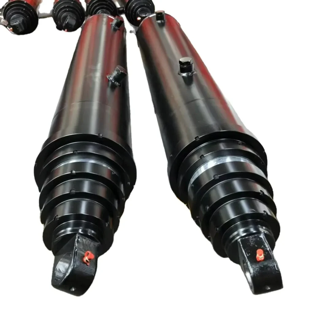
The hydraulic cylinder is the component in this power path that directly performs the lifting action. Pressurised oil acts on the effective pressure area, pushing the piston rod or telescopic cylinder sections outwards, which in turn lifts the body via the mounting points and lifting mechanism. Telescopic hydraulic cylinders utilise a multi-stage nested structure to achieve a long stroke with a short retracted length; ‘lifting cylinders’ are named according to their function and do not necessarily all feature a telescopic design.
Ignoring friction and pressure on the return side, the theoretical thrust is equal to the pressure multiplied by the effective pressure area; the speed of movement is related to the flow rate entering the working chamber and this area. In standard multi-stage telescopic cylinders, the effective area changes when switching between working stages; therefore, under the same pressure and flow rate, the thrust and extension speed may also vary. To determine whether a system is correctly matched, one must simultaneously verify ‘how much flow can be supplied at the required pressure’ and ‘how much thrust is required throughout the entire lifting process’. If the body is lifted with insufficient force or too slowly, the fault may lie in any of the following components: power take-off, oil supply, valve control or the hydraulic cylinder itself.
Engine Cylinder vs. Hydraulic Cylinder: Component Comparison
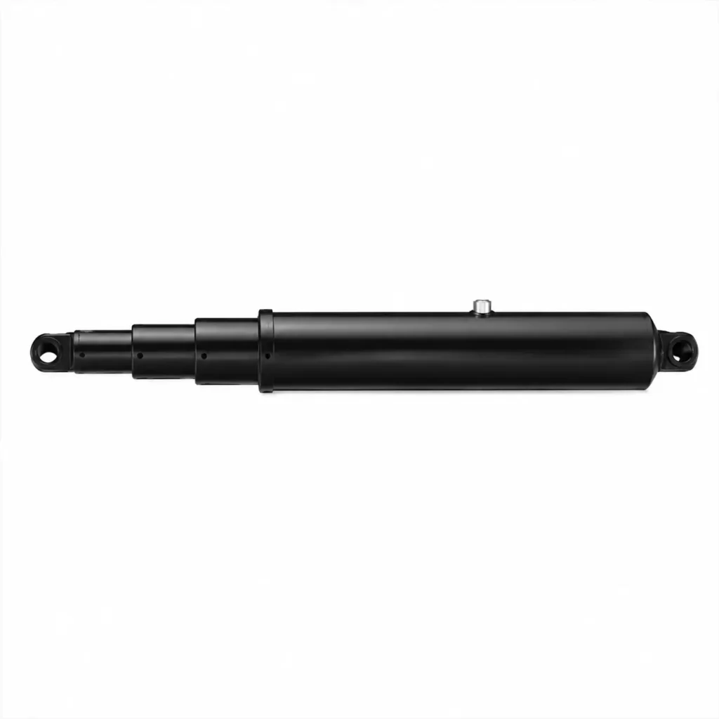
Many beginners confuse engine cylinders with hydraulic cylinders, as both feature a cylinder barrel, a piston and a reciprocating motion mechanism. However, their functions are entirely different. The primary function of an engine cylinder is to convert the thermal energy generated by fuel combustion into mechanical power, whilst the primary function of a hydraulic cylinder is to convert the pressure generated by hydraulic fluid into linear thrust or tensile force, which is used to perform the operational actions of machinery. Put simply, the engine cylinder is responsible for ‘generating power’, whilst the hydraulic cylinder is responsible for ‘performing actions’.
a. Energy Source and Working Medium
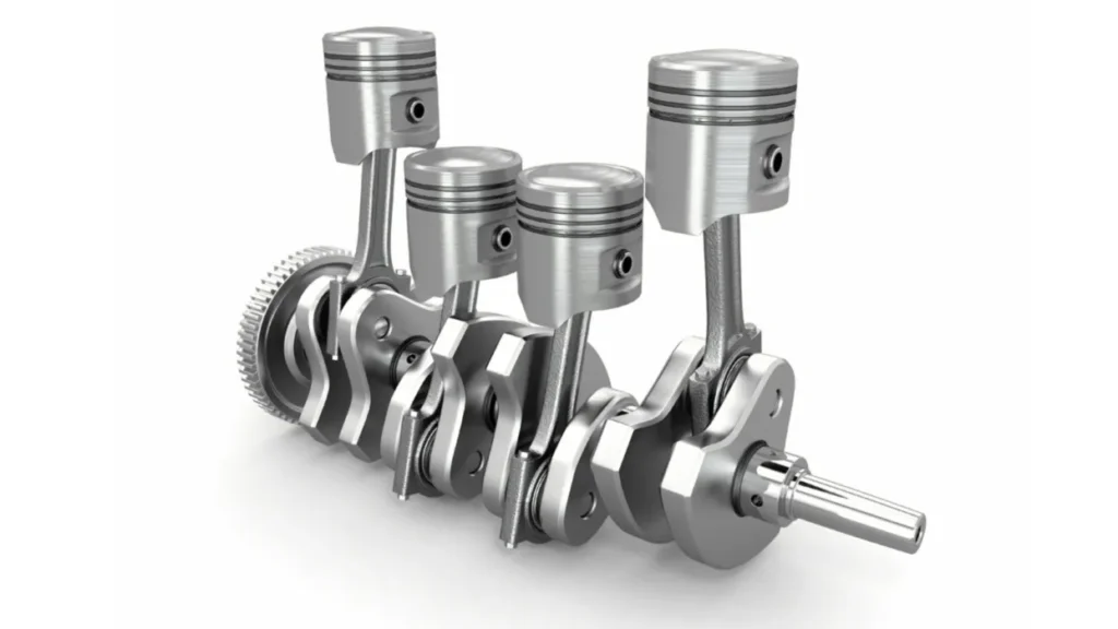
An engine cylinder (Engine Cylinder) relies on fuel combustion to generate energy. Fuel and air are mixed and combusted inside the cylinder, producing high-temperature, high-pressure gas that drives the piston. Subsequently, the piston drives the crankshaft (Crankshaft) to rotate via the connecting rod (Connecting Rod), converting reciprocating motion into rotational power. For example, a car engine utilises multiple cylinders working in sequence to provide propulsion for the vehicle.
Hydraulic cylinders, on the other hand, rely on a hydraulic system for power. A hydraulic pump pressurises hydraulic fluid and delivers it into the cylinder barrel; the pressure acts on the piston’s surface area, causing the piston rod to move in a linear fashion. Hydraulic cylinders do not generate energy themselves; they are merely actuators within the hydraulic system, responsible for converting hydraulic energy into mechanical motion.
Therefore, when selecting the appropriate type of equipment, you must first determine what type of power the equipment requires. If the equipment requires continuous rotational output—such as in cars, generators or power machinery—an engine system is more suitable; if the equipment needs to push, pull, clamp or lift a component—such as in excavators, hydraulic presses or industrial clamping devices—a hydraulic cylinder is generally more appropriate.
b. Motion Output
Although engine cylinders and hydraulic cylinders both rely on piston movement, the final form of motion produced differs. The piston movement in an engine cylinder is merely an intermediate process; it ultimately needs to be converted into rotational motion via the crankshaft. Consequently, engines focus on combustion efficiency, rotational speed, torque output and power continuity. Hydraulic cylinders, on the other hand, directly produce linear motion. When hydraulic fluid enters the pressure chamber, it drives the piston to move, and the piston rod directly generates thrust or tensile force. For example, hydraulic cylinders in construction machinery can raise and lower buckets, whilst those in industrial equipment can clamp workpieces or move moulds.
If your equipment requires frequent position changes, control over travel distance, or significant linear force, hydraulic cylinders offer distinct advantages. For instance, if a piece of equipment needs to lift a load by 500 mm and hold it in a specific position, this task is typically accomplished using a hydraulic cylinder rather than being achieved directly via an engine. However, it should be noted that hydraulic cylinders are not the optimal choice for all linear motion applications. Where the load is light, the operating frequency is high, and high-speed, precise control is required, electric actuators may be more suitable. Therefore, before selecting a hydraulic cylinder, it is necessary to comprehensively consider the load, speed, precision and operating environment.
c. Pressure and Temperature Conditions
The operating environment of an engine cylinder is more complex due to the combustion process taking place inside. Cylinders must withstand high-temperature combustion gases, rapid pressure changes and prolonged thermal cycling; consequently, design priorities typically focus on heat resistance, combustion sealing and material wear resistance. For example, piston rings must minimise combustion gas leakage whilst maintaining good lubrication.
Although hydraulic cylinders do not involve combustion processes, they must withstand hydraulic pressure over extended periods. Key design considerations include the cylinder barrel’s pressure-bearing capacity, piston rod strength, seal reliability and resistance to contamination. Particularly in construction machinery and outdoor equipment, hydraulic cylinders are not only subject to internal pressure but are also affected by dust, moisture, impact loads and off-centre loads.
When selecting a hydraulic cylinder, it is not advisable to focus solely on system pressure. For example, in a hydraulic system operating at 16 MPa, a cylinder with a short stroke and a large-diameter piston rod may operate stably, whilst a cylinder with a long stroke and a small-diameter piston rod may be at risk of bending.
When selecting a cylinder, you should at least verify the following parameters:
- Operating Pressure
- Maximum Load
- Stroke Length
- Rod Diameter (Rod D
d. Seals, Lubrication and Failure Modes
Both engine cylinders and hydraulic cylinders require sealing mechanisms, though their purposes differ. Engine cylinders primarily use piston rings to control combustion pressure, whilst also allowing lubricating oil to form a protective film that reduces friction between the piston and the cylinder wall. Common issues include piston ring wear, cylinder wall wear, thermal deformation and a drop in compression pressure. Hydraulic cylinders primarily rely on piston seals, rod seals and wiper seals to maintain hydraulic oil pressure and prevent external contaminants from entering the cylinder. Common faults in hydraulic cylinders include external oil leaks, internal leaks and damage to the piston rod.
For example, when a hydraulic cylinder develops an oil leak, many people’s first instinct is to replace the seals, but this does not necessarily resolve the issue. If the piston rod surface is scratched, leakage may recur quickly even after fitting new seals. Therefore, during repairs, it is necessary to inspect both the condition of the seals and that of the metal components. For hydraulic cylinders operating outdoors over extended periods, such as those in construction machinery, particular attention must be paid to the surface treatment of the piston rod, dust-proof design and the selection of sealing materials, as contaminants entering the hydraulic system will significantly reduce the service life of the seals.
e. Maintenance and Replacement Scope
Engine cylinders are core components of the powertrain, and their maintenance typically involves the entire engine system. This includes, for example, checking the combustion conditions, replacing piston rings, inspecting cylinder liner wear and adjusting engine performance. Consequently, engine cylinder maintenance usually requires a high level of expertise.
The approach to hydraulic cylinder maintenance is more modular. In many cases, you can choose to repair the cylinder based on the extent of the damage, rather than necessarily replacing the entire unit. For instance, a minor leak may only require the replacement of the sealing assembly; if the piston rod is damaged, it can be replaced; if the cylinder barrel is severely worn, it may need to be re-machined or the entire assembly replaced. In practical maintenance, a common mistake is to overlook issues within the hydraulic system itself. For example, contaminated hydraulic fluid, filter failure or abnormal system pressure can all lead to premature failure of the hydraulic cylinder. If the hydraulic cylinder is simply replaced without addressing the underlying system causes, the newly installed cylinder may still experience the same problems.
f. Practical Selection Logic
When deciding whether to use an engine cylinder or a hydraulic cylinder, it is best to start by considering the function of the equipment rather than the structure of the components. If your objective is to generate rotational power—for example, to drive a vehicle or operate machinery—then an engine cylinder serves as the power source. If your objective is to move a component to perform an action—such as lifting, clamping or extending—then a hydraulic cylinder is the more suitable means of execution.
If you are selecting a hydraulic cylinder, you must first calculate the theoretical thrust:
F = P × A
Where:
- F = Output thrust (Force)
- P = Hydraulic pressure (Pressure)
- A = Effective piston area (Piston Area)
For example, at a system pressure of 16 MPa, the theoretical thrust of a hydraulic cylinder with a bore diameter of 63 mm is approximately:
F = 16 × π × 31.5² ≈ 49.9 kN
However, in actual design, selection cannot be based solely on theoretical thrust, as safety factors, friction losses, mounting methods and dynamic impacts must also be taken into account.
Which Hydraulic Cylinder Designs Are Used on Dump Trucks?
Common lifting mechanisms for tipper lorries include front-mounted telescopic, under-mounted vertical lift and scissor lift. You can start by checking where the hydraulic cylinders are mounted, then determine whether they lift the body directly or via a linkage mechanism. For common rear-tipping tippers, these mechanisms all allow the body to pivot around a rear hinge point, meaning it tips upwards around the connecting shaft at the rear of the body.
It is also important to distinguish between two concepts: the first three refer to the mounting position and lifting mechanism, whilst single-acting and double-acting refer to how the hydraulic cylinder extends and retracts. Therefore, a front-mounted telescopic system may utilise a single-acting cylinder, and a bottom-mounted lifting mechanism may utilise a double-acting cylinder; these classifications are not mutually exclusive.
Front-Mounted Telescopic Cylinders
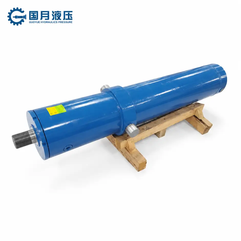
Front-mounted telescopic cylinders are typically installed at the front end of the body, close to the rear of the cab; some are housed in a dedicated recess at the front of the body. ‘Telescopic’ refers to a structure comprising multiple cylinder sections nested within one another, which extend in stages much like a telescopic aerial. This allows for a longer stroke—that is, the distance the cylinder travels from the retracted to the extended position—within a relatively limited space when retracted.
This design is commonly used in tipper lorries and tipper semi-trailers that require a significant lifting height. When the body is long, the front end must be raised high enough to achieve the required unloading angle, making the multi-stage telescopic structure particularly useful. However, a greater number of stages does not necessarily equate to greater lifting capacity; at the same pressure, the effective cross-sectional area of the subsequent, smaller-diameter stages is reduced, and the output thrust will also vary; this must be verified in conjunction with the entire lifting process.
When selecting a model, you should simultaneously confirm the retracted installation dimensions, total stroke, mounting brackets and the position of the rear pivot point. Manufacturers’ telescopic lifting products will also specify limitations regarding compatible body lengths, lifting capacity and mounting structures, rather than simply providing a cylinder diameter.
If there is insufficient space at the front of your body, or if the structure cannot provide reliable mounting support, a front-mounted solution is not suitable. Furthermore, do not treat the extended cylinder as a strut to prevent the body from rolling: it primarily withstands axial thrust—that is, forces along its own length—and cannot replace the vehicle’s lateral stability design.
Underbody Direct-Lift Cylinders
In the underbody direct-lift configuration, the cylinder is mounted beneath the body and pushes the body directly via connection points at both ends, without passing through a scissor linkage mechanism. Depending on space and lifting stroke requirements, single-stage or telescopic cylinders may be used; the term ‘underbody’ does not in itself specify the internal structure of the cylinder.
If you wish to retain space at the front of the body whilst there is a suitable mounting position between the chassis and the body, this solution is worth considering. Its force transmission path is relatively direct, but you should not assume that it requires less effort at any mounting angle. When the body first begins to lift, the mounting angle of the cylinder is often more important than it appears at first glance.
You can think of it as pushing a hinged, heavy plate: the closer the direction of thrust is to being parallel to the plate’s surface, the less effective it is in actually helping the plate to rotate. Consequently, although certain bottom-mounted direct-lift configurations generate significant cylinder thrust, the initial stage of lifting may still be laborious. When selecting a model, you must verify the ‘torque’, which is the force’s ability to rotate the body about the rear pivot point.
Scissor-Hoist Cylinders
In a scissor-lift system, a hydraulic cylinder drives a set of articulated lifting arms, which in turn raise the load platform. The ‘scissors’ you see are a mechanical mechanism; the hydraulic cylinder driving them is usually a standard piston-rod type cylinder, rather than a specialised ‘scissor cylinder’. This design allows engineers to adjust the force distribution during the lifting process by varying the length of the linkages and their attachment points. It is commonly found on engineering, municipal and landscaping transport vehicles, and there are also models suitable for larger load beds; it cannot simply be categorised as a structure exclusive to small tipper lorries.
If you wish to use a complete, integrated lifting assembly and the space beneath the body can accommodate the dimensions of the mechanism when folded, the scissor-type is worth considering. However, it adds lifting arms, pins and connecting components, which in turn increase weight, space requirements and maintenance points. If the underbody layout is very compact, you will need to check the folded height and range of motion carefully.
Single-Acting vs. Double-Acting Hoists
Single-acting lifting typically relies on hydraulic pressure to extend the cylinder and raise the body, with the body’s own weight causing the cylinder to retract. During descent, the hydraulic fluid returns to the reservoir via a control valve; therefore, ‘gravity-assisted descent’ does not mean allowing the body to fall freely. For conventional rear-tipping tipper designs that can reliably return to their resting position under their own weight, single-acting systems are a common choice.
Double-acting cylinders, on the other hand, utilise hydraulic pressure to actively extend and retract. You may wish to consider a double-acting solution if your hoisting design requires powered lowering, or if relying solely on gravity makes it difficult to achieve a reliable return stroke under normal operating conditions. For example, the Crysteel LO-BOY hoisting system employs double-acting hydraulics, providing both powered lifting and powered lowering.
However, double-acting does not automatically mean safer lowering, nor is it a universal solution to body jamming. Whether lowering is smooth also depends on the design of the control valves, hydraulic lines and load control.
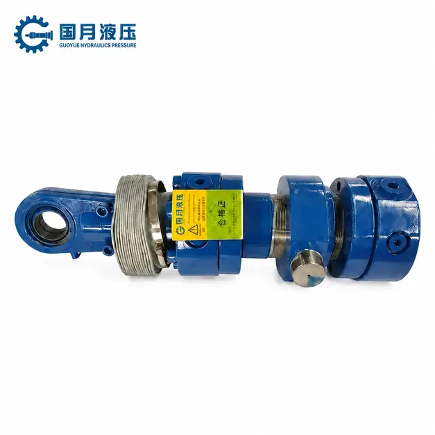
If the body cannot retract due to a jammed pivot point, structural deformation or mechanical interference, forcibly pulling it back hydraulically may exacerbate the damage.
When making a judgement, you can start by asking a specific question: “Within the permitted unloading angle, temperature and when the body is unladen, can the body reliably return to its lowered position under its own weight?” If so, a single-acting system is usually worth prioritising; if not, the cause should be identified first before determining whether a double-acting system is required. Regardless of the solution adopted, mechanical supports must be used in accordance with the manufacturer’s requirements before entering the underside of a raised body for maintenance; the body’s position must not be relied upon solely on the hydraulic cylinders or valves.
Which Component Is at Fault When the Bed Will Not Lift?
If the carriage cannot be lifted, it does not necessarily mean that the hydraulic cylinder is faulty. You should troubleshoot in the following order: power input, pump oil supply, valves and piping, and the cylinder and load. First, check whether power and hydraulic fluid are reaching the cylinder, then determine whether any components need to be repaired or replaced.
Engine or PTO Is Not Supplying Input Power
The PTO (Power Take-Off) is a device that transfers power from the vehicle’s drivetrain to the hydraulic pump. The fact that the engine is running does not necessarily mean that the pump is being driven. If there is absolutely no response when attempting to lift the load, you should first check the vehicle manual to ensure that the PTO is engaged and that the operating conditions are met, and have a mechanic inspect the drive connection. Even if the PTO indicator light is on, this alone does not prove that power has been transmitted to the pump.
If your vehicle uses an electro-hydraulic power unit, you should check the battery, motor and electrical connections rather than troubleshooting the PTO.
Pump Is Not Producing Pressure or Flow
The hydraulic pump is primarily responsible for delivering hydraulic fluid; pressure is only generated when the fluid encounters resistance whilst moving the load. You can think of flow as the volume of fluid delivered per unit of time, and pressure as the condition that generates thrust. Therefore, hearing the pump running does not necessarily mean it is providing sufficient lifting capacity.
First, check the fluid level at the location specified in the manual, then check whether the suction hose is crushed, blocked or drawing in air. If the load still cannot be lifted, a mechanic should measure the pressure and flow at the specified speed and under test conditions. Replacing the pump solely on the basis of low pressure may be a misdiagnosis, as the same symptoms can be caused by the pressure-limiting relief valve opening prematurely or by system leaks.
Valve, Hose, or Coupler Is Blocking Flow
Control valves are responsible for directing the hydraulic fluid to the correct location, whilst hoses and couplers provide the passageway. If a control valve has not switched to the correct position, if there is internal damage to a hose, or if a coupler in a quick-connect system is not fully engaged, the pump may operate whilst the cylinder remains stationary. In double-acting systems, also check that the return line on the other side of the cylinder is unobstructed.
If the fault occurs after replacing a hose or reconnecting a coupler, you should prioritise checking the pipe connections. A maintenance technician can compare pressures at relevant test points to determine where the restriction lies; High pressure at the pump outlet does not necessarily mean that normal pressure and flow are reaching the cylinder. Do not attempt to check for the presence of oil by loosening fittings whilst under pressure.
Hydraulic Cylinder Is Leaking, Binding, or Overloaded
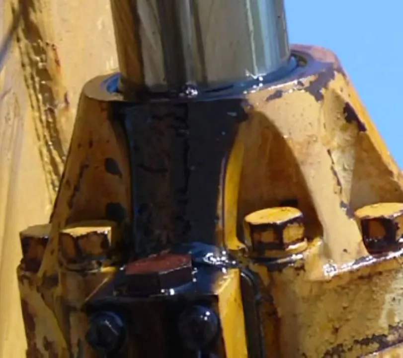
Once you have confirmed that the oil supply is normal, check whether the cylinder is visibly leaking, whether the piston rod is bent, and whether the body hinge or lifting mechanism is jammed. For cylinders with piston seals, internal leakage may also result in insufficient thrust; however, as telescopic cylinders vary in design, a single method for diagnosing internal leakage cannot be applied universally. If the vehicle can be lifted when empty but not when loaded, you should first verify the load and its distribution before testing the hydraulic performance.
Excessive concentration of cargo at the front of the body increases the lifting load; this phenomenon may also stem from pump wear and should not be directly attributed to cylinder failure. Do not arbitrarily increase the relief pressure to ‘boost the lifting force’.
Before carrying out any checks, park the vehicle on firm, level ground and secure it; when it is necessary to access the underside of the raised load bed, mechanical supports must be installed in accordance with the manufacturer’s instructions; do not rely solely on the hydraulic system to maintain the position of the load bed.
What Should Buyers Specify for a Dump-Truck Hoist Cylinder?
When purchasing hydraulic cylinders for tipper lorries, you cannot simply tell the supplier ‘how many tonnes need to be lifted’. The dimensions of the load bed, the installation location, the load distribution and the conditions of the hydraulic system will all affect whether a cylinder is suitable. The most practical approach is to provide a dimensioned installation drawing, supplemented by the following parameters.
Body Geometry, Payload, and Required Tipping Angle
You should provide the body length, unladen weight, maximum payload, the position of the rear pivot point, and the centre of gravity—that is, the point where the weight is concentrated. For a given payload, the closer the load is to the front of the body, the more difficult it is to lift; therefore, you cannot select a cylinder based solely on the payload. You should also specify the material to be transported and the target tipping angle. The unloading conditions for loose sand and gravel differ from those for sticky, wet materials; it is not necessarily the case that a larger angle is better. The supplier should calculate the required thrust and stroke based on the body’s geometry, and the permissible lifting angle must be confirmed by the vehicle’s overall designer.
Mounting Position and Retracted Length
Specify whether a front-mounted, under-mounted straight-lift or scissor-lift mechanism is to be used, and provide the mounting point locations, pin diameters, bracket widths and port orientations. The measurement reference for retracted length must be specified: for example, for cylinders mounted on pins at both ends, it is usually necessary to confirm the centre-to-centre distance between the pins when fully retracted; simply measuring the cylinder barrel length is insufficient.
You should also ask the supplier to verify the installation clearance when the body is lowered and raised. The fact that the external dimensions fit does not guarantee that there will be no collisions during movement; misalignment during installation may also subject the cylinder to lateral forces, causing wear, leakage or jamming.
Stroke, Stage Count, and Maximum Extension
Stroke refers to the distance travelled by the cylinder from fully retracted to fully extended; stage count refers to the number of moving stages in a telescopic cylinder that extend sequentially. You should verify the total stroke, retracted length and maximum extension simultaneously, to avoid mistaking the stroke for the total length of the cylinder when fully extended. Where installation space is limited but a long stroke is required, a multi-stage telescopic design is more advantageous; however, a higher number of stages does not necessarily equate to greater load-bearing capacity. Request that the supplier check the thrust at each stage of extension, as well as the load-bearing capacity at maximum extension; do not merely confirm that the cylinder ‘can achieve the unloading angle’.
Working Pressure, Bore, and Column Load
Provide the system working pressure, relief valve set pressure and pump flow rate. The relief valve is responsible for limiting the maximum pressure, whilst the flow rate affects the lifting speed. The bore refers to the internal diameter of the cylinder barrel; for telescopic cylinders, you must also verify the effective pressure area for each stage, as the theoretical thrust depends on pressure × effective pressure area.
Column load refers to the compressive load borne by the cylinder along its length. When the cylinder is fully extended, buckling—that is, bending instability under compression—may occur even if the theoretical thrust is sufficient. Therefore, you should require the supplier to verify the load-bearing capacity throughout the entire lifting process, rather than relying on increased pressure to compensate for inadequate selection.
Application Duty, Environment, and Safety Devices
Inform the supplier of the approximate number of lifting cycles per day, whether operation is continuous, the target lifting time, as well as ambient temperature, the type of hydraulic oil, and conditions such as dust and salt spray. This information will influence the configuration of seals, corrosion protection and dust protection; the same configuration should not be applied indiscriminately to both occasional unloading and frequent continuous unloading.
You should also clarify whether a single-acting system with gravity-assisted retraction or a double-acting system requiring powered retraction is to be used, and confirm with the vehicle manufacturer who is responsible for providing configurations such as pressure limiting, descent control, pipe rupture protection and mechanical support for maintenance. The hydraulic cylinder is a lifting component and must not be used as an anti-tipping support; furthermore, the use of larger cylinders must not be employed to compensate for insufficient vehicle stability.
Frequently Asked Questions About Dump-Truck Cylinders
Does the Truck Engine Directly Push the Dump Body Up?
No, it does not push it directly. In a typical engine-driven hydraulic system, the engine first drives a hydraulic pump via the PTO (Power Take-Off, i.e. the device that transfers the vehicle’s power to the working equipment). The pump delivers hydraulic fluid to the cylinder; the pressure of the fluid acts on the effective area inside the cylinder, generating thrust that causes the cylinder to extend and lift the body. You can think of this power chain as follows: the engine provides power, the PTO transmits that power, the hydraulic pump delivers the fluid, and the hydraulic cylinder performs the lifting action. Some vehicles use electric hydraulic pumps, but it is still the hydraulic cylinder that ultimately lifts the load bed.
The most common point of confusion here is the distinction between ‘lifting quickly’ and ‘lifting heavy loads’. Flow rate—that is, the volume of fluid delivered per unit of time—primarily affects lifting speed; whilst pressure, combined with the effective cross-sectional area of the hydraulic cylinder, determines the thrust. Therefore, when the load bed cannot be lifted, simply pressing the accelerator is not a reliable solution: increasing the engine speed may boost the fuel supply rate, but it cannot enable the system to safely exceed its designed lifting capacity. You should first check whether the load exceeds the limit, whether it is distributed correctly, and whether the PTO is correctly engaged.
Is the PTO the Same as the Hydraulic Pump?
No, they are two separate components that are interconnected but have different functions. The power take-off (PTO) is typically mounted on the gearbox and provides rotational power; the hydraulic pump receives this power and delivers oil from the reservoir to the hydraulic circuit. Even if the pump is mounted directly on the PTO and appears to form a single assembly, the two cannot be used interchangeably. To determine this, you should check their respective nameplates and parts diagrams, rather than relying solely on appearance or mounting position. Reference: Muncie PTO Technical Manual
If you need to replace one of them, ‘the connection fitting’ is only the first step. The power take-off must be compatible with the gearbox and meet the pump’s requirements for rotational speed, direction of rotation and torque—that is, the force driving the pump; the hydraulic pump, in turn, must match the system pressure and required flow rate. For example, fitting a pump with a higher flow rate per revolution may speed up lifting, but at the same pressure, it will also increase the torque borne by the power take-off.
Why Are Telescopic Cylinders Common on Dump Trucks?
This is because dump trucks need to be ‘short when retracted and long when extended’. Telescopic cylinders consist of multiple nested sleeves, similar to a telescopic aerial, and can provide a long stroke—that is, the distance travelled from fully retracted to fully extended— within a short retracted length. This is particularly well-suited to front-mounted lifting mechanisms on tipper bodies where installation space is limited but a significant lifting distance is required. Standard single-stage cylinders, whilst capable of providing the same stroke length, are often longer when retracted, which can make them difficult to accommodate. However, lifting systems utilising a linkage mechanism beneath the tipper body can also employ standard cylinders; not all tipper lorries are required to use telescopic cylinders.
When selecting a cylinder, do not simply ask, ‘How many tonnes can this cylinder lift?’ . You need to provide the supplier with the body’s unladen weight, rated load and its centre of gravity, the cylinder mounting points, the retracted installation length and the target lifting angle, and request a verification of the entire lifting process. This is because as the body rotates about the rear pivot point, the angle at which the cylinder is loaded changes, and the effective compression area varies across different telescopic stages; simply comparing the thrust of the highest stage does not guarantee suitability throughout the entire stroke. Another common mistake is treating the hydraulic cylinder as an anti-tilt strut: whilst it is responsible for lifting, it cannot replace the vehicle’s stability design.
Can a Dump Body Lower With the Engine Off?
Some can, but this depends on the lowering circuit; it is not simply a matter of whether the engine is switched off. A common type of single-acting cylinder is one in which the hydraulic fluid is only responsible for pushing in one direction: it extends and lifts when fluid is supplied, whilst lowering typically relies on the body’s own weight to push the cylinder back, simultaneously returning the fluid in the cylinder to the reservoir. Therefore, provided the control valve can open the return line and the body’s weight is sufficient to overcome friction and return flow resistance, the body may still lower after the hydraulic pump has stopped.
However, ‘the pump does not need to run’ does not equate to ‘the control system does not require power’. Electrically controlled valves may still require a power supply, whilst pneumatically controlled valves require sufficient air pressure; some load-holding valves require pilot pressure, that is, the control oil pressure used to open the valve. If double-acting cylinders are used—where both extension and retraction are hydraulically driven—whether the load can descend after the engine has been switched off must be determined based on the specific circuit.
Choosing a Trusted Hydraulic Cylinder Manufacturer
From standard hydraulic cylinders to custom solutions, we help you improve equipment performance, delivery reliability, and batch consistency
Explore Rivmate Cases

Hey There, I'm Melody!
We are a hydraulic cylinder manufacturer. For over 20 years, we have focused on producing reliable hydraulic cylinders. Need a hydraulic cylinder solution? Feel free to contact us.