
Home / What Determines the Speed of a Hydraulic Cylinder?
What Determines the Speed of a Hydraulic Cylinder?
- Author: GY Hydraulic
- 20+ Years of Manufacturing
The speed of a hydraulic cylinder is primarily determined by the actual flow rate entering the cylinder and the effective pressure area on the inlet side. Flow rate is the volume of fluid entering per unit of time, and the effective pressure area is the area over which the hydraulic pressure acts on the piston. Assuming no leakage, the calculation is: Speed = Flow Rate ÷ Effective Pressure Area. Therefore, for a given cylinder, the more fluid entering, the faster it typically moves; for the same flow rate, the larger the effective pressure area, the slower the movement.
If you notice that a hydraulic cylinder is moving slowly, you cannot solve the problem simply by increasing the pressure. The pressure must be sufficient to overcome the load, but the actual speed is also affected by control valves, line resistance, oil temperature, and internal leakage. For common single-rod, double-acting hydraulic cylinders, when the inflow flow rate is the same during extension and retraction, retraction is usually faster because the effective pressure area on the rod side is smaller. Understanding these relationships can help you calculate the required flow rate and more accurately identify the cause of slow operation.
Table of Contents
The Direct Answer: Flow Rate Divided by Effective Piston Area
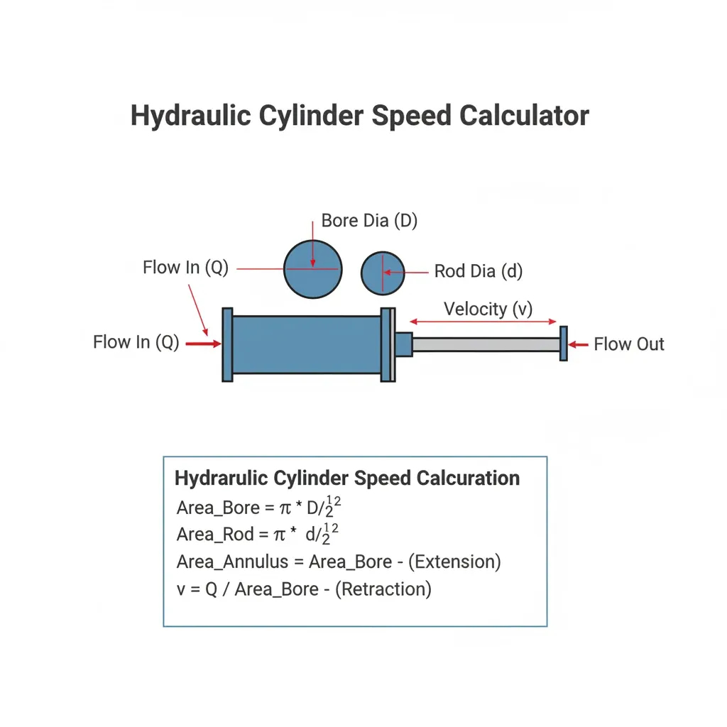
The theoretical speed of a hydraulic cylinder is equal to the actual flow rate entering the working chamber divided by the effective piston area on that side, i.e., v = Q ÷ A. Here, v is the piston speed, Q is the volume of fluid entering per unit time, and A is the effective area of the piston displaced by the fluid. This relationship applies to motion calculations that neglect factors such as leakage and fluid compressibility.
Why Flow and Area Determine Speed
You can think of it this way: for every distance the piston moves forward, the inlet side must supply a corresponding volume of fluid. The larger the area under pressure, the more fluid is required to move the piston the same distance. Therefore, when the area remains constant, doubling the flow rate doubles the theoretical speed; when the flow rate remains constant, doubling the area halves the theoretical speed. For example, after replacing a cylinder with a larger bore, even if the thrust increases, the extension stroke will slow down if the fluid supply flow rate remains unchanged.
Use the Area for the Direction of Travel
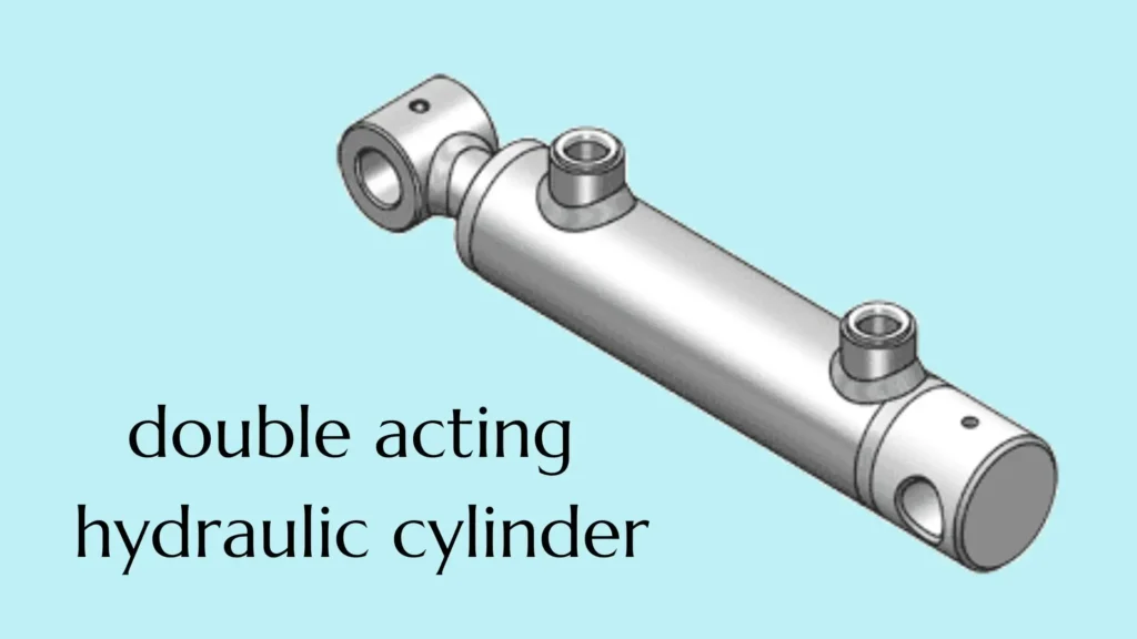
For a common single-rod, double-acting hydraulic cylinder, the full piston area is used during extension; during retraction, the annular area—after subtracting the cross-sectional area of the piston rod—is used. If D represents the cylinder bore diameter and d represents the rod diameter, the extension area is πD²÷4, and the retraction area is π(D²-d²)÷4. Here, the cylinder diameter refers to the inner diameter of the cylinder barrel, not the outer diameter.
When calculating the speed in a given direction, you must use the flow rate and area corresponding to that direction. Because the area on the retraction side is smaller, the theoretical retraction speed is faster when the flow rates in both directions are equal. This conclusion applies to standard supply circuits and cannot be directly applied to special differential circuits or multi-stage telescoping cylinders.
Calculating Speed with Consistent Units
If you are using flow rate in L/min and area in mm², you can directly use the following conversion formula to obtain the speed in mm/s:
Speed (mm/s) = Flow Rate (L/min) × 1,000,000 ÷ [60 × Area (mm²)]
For example, assume the cylinder bore is 50 mm, and the actual flow rate entering the cylinder during extension is 10 L/min. The piston area is approximately 1,963 mm², and the theoretical extension speed is approximately 84.9 mm/s. If the piston moves 300 mm at this constant speed, the theoretical time would be approximately 3.53 seconds, excluding startup, deceleration, or dwell times.
Use Actual Cylinder Flow, Not Just Pump Flow
The Q in the formula should be the flow rate entering the working chamber of the target cylinder; it cannot be directly substituted with the pump’s nameplate flow rate. For example, if a pump supplies fluid to multiple actuators simultaneously, or if part of the fluid returns to the tank via other passages, the flow rate entering this particular cylinder may be lower.
In practical applications, you must also verify that the system pressure is sufficient to overcome the load. If the cylinder is blocked by the load, it will not continue to move based on the pump flow rate alone, even if the pump is still supplying fluid. Significant leakage, air entrainment, and fluid compression during startup can also cause the actual speed to deviate from simple calculations.
A practical approach is: Measure the time required for the cylinder to travel a fixed distance in the middle section when the load and oil temperature are similar, then calculate the average speed using “distance ÷ time.” Avoid the startup and end-of-stroke deceleration zones for more meaningful results. If the measured speed is significantly slower than the theoretical value, first verify the actual oil flow rate and circuit conditions rather than simply increasing the pressure.
Cylinder Speed Formulas for Extension and Retraction
For a standard single-rod, double-acting hydraulic cylinder, the extension speed is equal to the oil flow rate divided by the total piston area, and the retraction speed is equal to the oil flow rate divided by the annular area after subtracting the piston rod. The following formula applies to theoretical calculations in a standard directional control circuit, assuming the cylinder can drive the load normally and neglecting the effects of leakage and fluid compressibility.
a. Extension Speed Formula
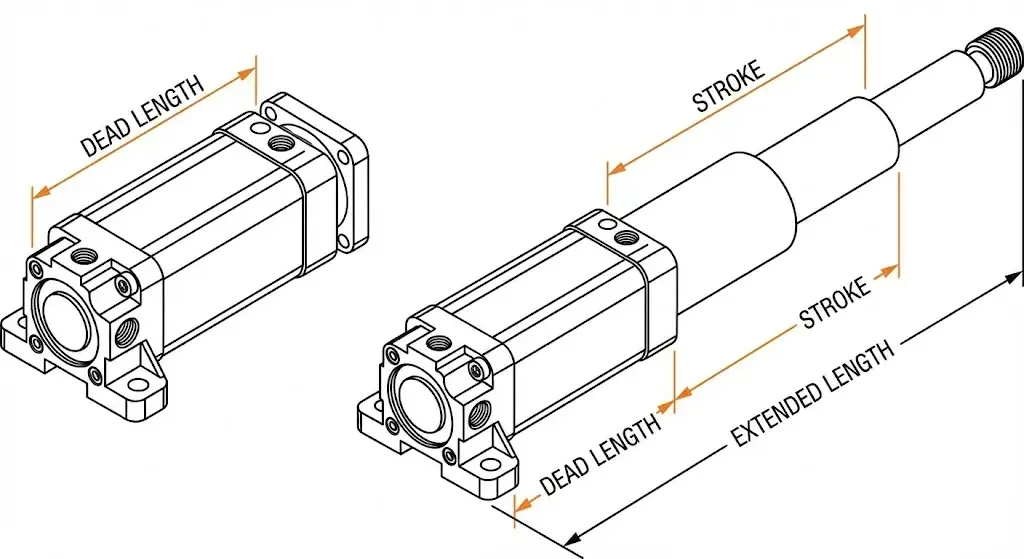
During extension, fluid enters the rodless chamber—that is, the side of the piston not connected to the piston rod. The fluid acts on the full piston area, so you must use the cylinder bore to calculate the area. Here, the cylinder bore refers to the inner diameter of the cylinder barrel, not the outer diameter.
Effective extension area: A₁ = π × D² ÷ 4
Extension speed: v₁ = Q₁ ÷ A₁
Here, D represents the cylinder bore diameter, A₁ represents the effective extension area, Q₁ represents the actual flow rate entering the rodless chamber during extension, and v₁ represents the extension speed. π is taken as approximately 3.1416, and D² represents the cylinder bore diameter squared.
If flow rate is given in L/min (liters per minute) and area in mm² (square millimeters), you can directly use the following conversion formula:
Extension speed (mm/s) = Q₁ × 1,000,000 ÷ (60 × A₁)
For example, with a cylinder bore of 50 mm and an extension flow rate of 10 L/min, the piston area is approximately 1,963.5 mm². Substituting these values yields a theoretical extension speed of approximately 84.9 mm/s.
b. Retraction Speed Formula
During retraction, fluid enters the rod chamber—that is, the side of the piston connected to the piston rod. Since the piston rod occupies part of the area, you must subtract the cross-sectional area of the piston rod from the total piston area to obtain the effective annular area.
Effective retraction area: A₂ = π × (D² − d²) ÷ 4
Retraction Speed: v₂ = Q₂ ÷ A₂
Here, d represents the rod diameter, A₂ represents the effective area during retraction, Q₂ represents the actual flow rate entering the rod chamber during retraction, and v₂ represents the retraction speed. When flow rate is expressed in L/min and area in mm², the conversion formula is:
Retraction speed (mm/s) = Q₂ × 1,000,000 ÷ (60 × A₂)
Using the 50 mm cylinder bore, assuming a rod diameter of 30 mm and a retraction flow rate of 10 L/min, the annular area is approximately 1,256.6 mm², and the theoretical retraction speed is approximately 132.6 mm/s. Note that the area calculation uses D² − d², not (D − d)².
c. Comparing Extension and Retraction
Speeds can only be directly compared using the area ratio when the oil flow rate is the same in both directions. In a typical single-rod hydraulic cylinder, the effective area during retraction is smaller; therefore, the same oil flow rate can move the piston a greater distance, resulting in a faster retraction speed.
At the same oil flow rate, retraction speed ÷ extension speed = D² ÷ (D² − d²)
In the example above, the speed ratio is 1.5625, meaning the theoretical retraction speed is approximately 56.3% faster than the extension speed. If the cylinder moves 300 mm in both directions, disregarding acceleration, deceleration, and dwell time, the calculation results are as follows:
| Calculation Item | Extension | Retraction |
|---|---|---|
| Cylinder Bore | 50 mm | 50 mm |
| Rod Diameter | 30 mm | 30 mm |
| Oil Flow Rate | 10 L/min | 10 L/min |
| Effective Area | Approx. 1,963.5 mm² | Approx. 1,256.6 mm² |
| Theoretical Speed | Approx. 84.9 mm/s | Approx. 132.6 mm/s |
| Theoretical Time to Travel 300 mm | Approx. 3.53 seconds | Approx. 2.26 seconds |
If you want the speeds to be the same in both directions, you should calculate the required flow rates separately. For example, if this cylinder uses 10 L/min during extension and approximately 6.4 L/min during retraction, theoretically, the same speed can be achieved.
d. Check the Circuit Before Applying the Formulas
The flow rate in the formula must correspond to the area: if using the inlet flow rate, divide by the inlet-side area; if using the outlet flow rate, divide by the outlet-side area. Do not directly divide the outlet flow rate measured in the rodless chamber during retraction by the area of the rod chamber. Since the areas on both sides are different, the inlet and outlet flow rates during normal operation will also differ.
You also cannot apply the pump’s flow rate directly to all circuits. Differential circuits return a portion of the return flow to the inlet side; telescoping cylinders require calculation based on the effective area at the current stroke stage; and for single-acting hydraulic cylinders returning by gravity or spring, the return speed cannot be estimated based on the pump’s supply flow rate. Before calculating, first confirm the cylinder configuration, direction of motion, and flow measurement location.
How Bore Size and Rod Diameter Change Speed
Under conditions of equal actual oil flow rate, the larger the bore diameter, the slower the extension speed; when the bore diameter remains constant, the thicker the piston rod, the faster the retraction speed. This is because these dimensions alter the effective area—that is, the working area corresponding to the force exerted by the hydraulic fluid on the piston. The following comparison applies to a standard single-rod, double-acting hydraulic cylinder, assuming a conventional directional control circuit and neglecting the effects of leakage and hydraulic fluid compressibility.
Bore Size: Larger Cylinders Move More Slowly at the Same Flow
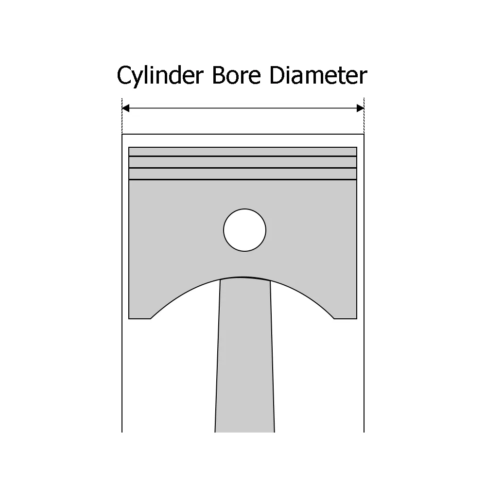
The bore size is the inner diameter of the cylinder barrel and determines the total piston area during extension. As the bore size increases, more fluid is required to move the piston the same distance. Therefore, if the fluid flow rate remains constant, a larger cylinder will extend more slowly.
Extension speed is inversely proportional to the square of the bore size. For example, if the bore size increases from 50 mm to 100 mm, the area quadruples, and the theoretical extension speed at the same flow rate drops to one-fourth of the original value. If the rod diameter remains constant, increasing the bore size also increases the area on the retraction side, reducing the retraction speed.
However, this does not mean that a smaller bore size is always more suitable. At the same pressure, reducing the bore diameter also reduces thrust. If the load remains unchanged, the system may require higher pressure to move it, or it may even fail to start. You should first confirm that the output force is sufficient before comparing speeds.
Rod Diameter: A Thicker Rod Increases Retraction Speed
The piston rod diameter determines the area occupied on the rod side. When the bore diameter remains constant, the larger the rod diameter, the smaller the remaining annular area. This annular area is the effective area during retraction; therefore, the same oil flow rate can produce faster retraction.
When the cylinder bore and actual oil flow rate remain constant, increasing the piston rod diameter does not directly change the theoretical extension speed. The extension side still utilizes the full piston area. However, a thicker piston rod reduces the retraction area, so at the same supply pressure—and ignoring return pressure and friction—the retraction force will also decrease. For mechanisms requiring retraction under load, you cannot simply aim for a faster return stroke.
Compare the Effects with an Example
Assume that for all three scenarios, the actual oil flow rate during both extension and retraction is 10 L/min. The table below varies only the cylinder bore or rod diameter to illustrate the effect of dimensions on theoretical speed.
| Scenario | Cylinder Diameter | Rod Diameter | Theoretical Extension Speed | Theoretical Retraction Speed |
|---|---|---|---|---|
| Base Scenario | 50 mm | 30 mm | 84.9 mm/s | 132.6 mm/s |
| Increased Cylinder Bore, Rod Diameter Unchanged | 63 mm | 30 mm | 53.5 mm/s | 69.1 mm/s |
| Increased Rod Diameter, Cylinder Bore Unchanged | 50 mm | 40 mm | 84.9 mm/s | 235.8 mm/s |
As you can see, increasing the cylinder bore results in slower speeds in both directions; when only the piston rod is thickened, the theoretical extension speed remains unchanged, while the retraction speed increases. However, the theoretical retraction force of the third option is only 56.25% of the baseline option under the same pressure. These figures illustrate the trade-off between speed and force output and do not imply that the third option is the better choice.
Check Return Flow Before Choosing a Larger Rod
Faster retraction also means that the rodless chamber must discharge fluid more quickly. For the configuration in the table above with a 50 mm bore diameter and 40 mm rod diameter, when the retraction flow rate is 10 L/min, the theoretical discharge rate of the rodless chamber is approximately 27.8 L/min. Therefore, the flow capacity of the return valve and piping cannot be determined directly based on the inlet flow rate.
If the return flow path is too restricted, it will create high back pressure—that is, pressure that hinders fluid discharge. This reduces the available retraction force and may cause the actual speed to fall short of the theoretical value. Before changing the rod diameter, you should have the supplier verify the retraction force, return flow rate, permissible operating speed, and piston rod stability. For differential circuits, multi-stage telescopic cylinders, or cylinders that rely on gravity for return, recalculations must be performed based on their respective designs and hydraulic circuits.
Why Pump Flow Matters More Than Pressure for Speed
When the pressure is sufficient to move the load, the speed of the hydraulic cylinder depends primarily on the actual flow rate entering the cylinder, rather than the pressure setting. Flow rate refers to the amount of fluid delivered per unit of time and determines how fast the piston can move; pressure, together with the effective cross-sectional area, determines the force output, which helps the cylinder overcome the load. Therefore, while “flow rate affects speed, and pressure affects force” can serve as a general guideline, it should not be interpreted to mean that pressure is completely unrelated to speed.
More Flow Moves the Piston Faster
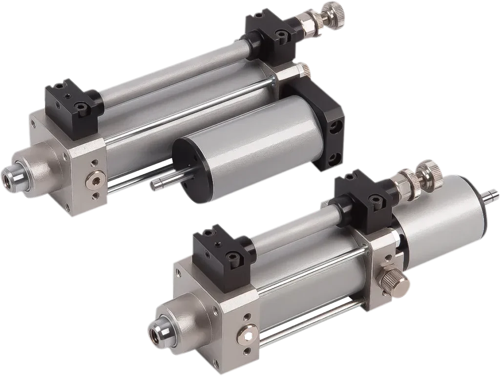
For every distance a hydraulic cylinder moves, a corresponding volume of fluid must fill the working chamber. For a given cylinder, if the actual inflow rate increases—and provided the load, return line, and other conditions permit—the piston can move faster.
For example, assuming a cylinder bore of 50 mm, if the extend flow rate increases from 10 L/min to 20 L/min—ignoring leakage and fluid compressibility—the theoretical extend speed would increase from approximately 84.9 mm/s to 169.8 mm/s. However, if the flow rate remains at 10 L/min, simply raising the system’s maximum pressure will not automatically double the theoretical speed.
Pressure Must Be High Enough to Move the Load
Before a hydraulic cylinder begins to move, the hydraulic pressure must overcome the resistance generated by the load, friction, and pressure on the return side. If the available pressure is insufficient, the cylinder may stall; in this case, even if the pump is still running, the movement speed cannot be calculated directly from the pump flow rate.
For example, when a heavy load causes the system to reach the relief valve’s set pressure, some or most of the pump flow may return to the tank via the relief valve. Since the relief valve is designed to limit system pressure, the flow entering the cylinder and generating motion is reduced. Increasing the pressure limit can sometimes restore cylinder motion, provided that the design has been verified and the permissible limits of all components are not exceeded. This is a solution for insufficient output, not a general method for adjusting speed.
Pump Flow Is Not Always Cylinder Flow
The pump’s nominal flow rate does not necessarily all enter the target cylinder. Restrictions from control valves, simultaneous operation of multiple actuators, internal leakage, and the pump’s own control mechanism can all alter the actual flow rate allocated to the cylinder.
For example, a fixed-displacement pump has a theoretically fixed displacement per revolution, and its output primarily varies with speed; a variable-displacement pump, on the other hand, can alter its displacement per revolution. Certain pressure-compensated variable-displacement pumps automatically reduce displacement and output flow when a set pressure is reached. Therefore, you cannot rely solely on the pump’s “maximum flow rate”; you must also verify how much flow it can sustain at the target pressure and speed.
Pressure Can Affect Speed Through the Valve
For standard throttle valves—which restrict flow by narrowing the fluid passage—flow rate depends not only on the size of the opening but also on the pressure differential across the valve, i.e., the difference in pressure on either side. Therefore, even if the valve opening remains constant, the cylinder speed may change when load variations cause fluctuations in the pressure differential.
If your equipment needs to maintain a relatively stable speed when the load changes, you may want to consider a pressure-compensated flow control valve. It automatically adjusts to minimize the impact of pressure differential fluctuations on flow rate, but it still requires sufficient oil supply and operating pressure differential. Pressure compensation cannot magically provide additional flow to a system with insufficient oil supply.
Check Available Power Before Increasing Flow
Increasing the flow rate also requires sufficient drive power. The theoretical hydraulic power supplied by the pump to the fluid can be estimated using the following equation, where the pressure is the pressure difference between the pump outlet and inlet:
Hydraulic power (kW) = Pressure differential (MPa) × Flow rate (L/min) ÷ 60
For example, at a pressure differential of 10 MPa and a flow rate of 20 L/min, the theoretical hydraulic power is approximately 3.33 kW; if the pressure differential is increased to 20 MPa while maintaining the same flow rate, approximately 6.67 kW is required. The actual power required by the motor or engine must also account for losses. Therefore, the highest pressure and maximum flow rate that a pump can achieve may not necessarily be attainable simultaneously under existing power conditions.
What to Check When the Cylinder Is Too Slow
When troubleshooting insufficient speed, record the load, oil temperature, cylinder inlet and outlet pressures, and actual flow rate simultaneously. If the pressure is sufficient to overcome the load but the inlet flow rate is lower than the calculated requirement, focus on checking the pump output, valve opening, and flow distribution; if the system has reached the maximum pressure but the cylinder still struggles to move, check the load, mechanical binding, and power-load matching.
How Load, Friction, and Pressure Losses Affect Actual Speed
Loads, friction, and pressure losses affect the final speed by altering the pressure required by the cylinder, the actual flow rate, and motion stability. “Speed = Flow Rate ÷ Effective Area” remains the fundamental relationship, but you cannot assume that the pump will always deliver the same flow rate to the cylinder. You need to consider the direction of the load, the control circuit, and the system’s supply capacity to determine why the actual motion is slower than calculated.
Higher Loads Do Not Always Mean Lower Speed
When the load increases, the cylinder typically requires higher pressure to continue moving. If the system can maintain the flow rate entering the cylinder and has not reached pressure or power limits, an increase in load does not necessarily reduce the steady-state speed. For example, when using appropriate pressure-compensated flow control, the system can minimize the impact of load variations on speed within a certain range.
However, the situation may differ with standard throttling control. Throttling control regulates flow by narrowing the fluid passage. If the supply pressure remains essentially constant, an increased load raises the pressure at the cylinder inlet, reducing the pressure differential across the inlet throttle orifice. As a result, the flow rate may decrease, causing the cylinder to slow down. Therefore, even under the same “increased load” conditions, speed performance may vary across different circuits.
Friction Can Delay Starting and Cause Uneven Motion
Friction arises from seals, guide components, and the moving mechanisms of the equipment itself. It increases the force required for starting and operation, but cannot simply be subtracted from the theoretical speed by a fixed percentage. If the actual flow rate remains constant and the system has sufficient output capacity, increased friction may primarily manifest as a rise in operating pressure.
At low speeds, you may also encounter “creeping,” where the piston rod stops and starts intermittently. Differences in friction between stationary and sliding states are one possible cause. For example, misalignment during installation or excessive resistance in the guide rails can cause the cylinder to first build up pressure and then move suddenly once the resistance is overcome. In such cases, you should inspect the installation, guidance, sealing, and lubrication conditions rather than simply increasing the flow rate. There have also been specific experimental studies on friction variations and the “creeping” phenomenon during low-speed movement of hydraulic cylinders. ScienceDirect
Pressure Losses Reduce the Pressure Available at the Cylinder
Pressure loss, also known as pressure drop, is the decrease in pressure that occurs when fluid flows through components such as valves, hoses, and fittings. Therefore, the pressure at the pump outlet is not equal to the pressure at the cylinder inlet. Significant pressure drops may occur at the target flow rate if the passages are too narrow, the piping is too long, or there are significant local restrictions.
For example, suppose that at a given operating flow rate, the pump outlet pressure is 12 MPa and the pressure drop in the inlet path is 2 MPa; in that case, the cylinder inlet pressure would be approximately 10 MPa. If this is still sufficient to drive the load, the speed may not decrease; however, if the required pressure exceeds the available range, the system may reduce the oil supply, divert flow through a relief valve, or bring the cylinder to a stop. A pressure drop does not necessarily mean the speed will decrease; the key factor is whether the system still has sufficient pressure and flow reserve.
Return Backpressure Also Consumes Available Force
Return backpressure is the pressure generated on the outlet side due to resistance from valves and piping. It acts on the opposite side of the piston, partially offsetting the driving force. For a single-rod hydraulic cylinder in the extended position, when acceleration is neglected, the force available to overcome the external load can be approximated as:
Available extension force = Non-rod chamber pressure × Total piston area – Rod chamber pressure × Annular area – Friction force
You cannot simply subtract the pressure on one side from that on the other and then multiply the result by the total piston area, because the pressurized areas on each side are different. For example, if the return valve orifice is too small, it may increase backpressure, requiring the cylinder to have a higher inlet pressure to maintain operation. However, some circuits intentionally incorporate return resistance to stabilize motion; this should not be arbitrarily eliminated just to increase speed.
Gravity-Assisted Loads Can Cause Motion to Be Too Fast
Loads do not always impede motion. When a heavy object is lowering, gravity may actively drive the cylinder’s movement; this is known as load override, meaning the load tends to cause the actuator to accelerate on its own. In this case, the problem may shift from “motion being too slow” to “lowering too fast or erratically.”
For example, when a lifting mechanism is lowering, one cannot assume that the speed is under control simply by reducing the inlet flow. It is necessary to use appropriate components, such as balancing valves, in conjunction with the circuit to control the load-driven return flow. One of the functions of a balancing valve is to control this type of load override; its selection and setting should be matched to the specific mechanism.
Compare Speed Under Consistent Conditions
A practical troubleshooting method is to compare the mid-stroke movement speeds under light load and normal operating loads at similar oil temperatures, while recording the cylinder inlet and outlet pressures and actual flow rates. If the same cylinder slows down under load and the inlet flow rate decreases simultaneously, this indicates the need for further inspection of the supply and control circuits; if the primary symptoms are difficult startup or intermittent jerking, you should also focus on checking for friction, installation issues, and mechanical binding.
You should avoid taking measurements during startup or in the end-of-stroke deceleration zones, and have qualified personnel use gauges rated for the system’s parameters. Relying solely on the pressure gauge on the pump side or simply concluding that “the load has become heavier” is insufficient to determine where adjustments are needed.
Flow-Control Valves and Common Speed-Control Circuits
Flow control valves regulate motion speed by adjusting the volume of oil entering or leaving a hydraulic cylinder. Common circuit configurations include inlet throttling, return line throttling, and bypass speed control. When selecting a valve, you must first determine whether the load is resisting motion or actively driving the cylinder to accelerate; then consider speed stability, oil supply method, and heat dissipation requirements. The performance of the same valve can vary significantly depending on its installation location.
Throttle Valves and Pressure-Compensated Flow Controls
Standard throttle valves limit flow by adjusting the opening of the flow passage, but the actual flow rate is also affected by the pressure differential across the valve orifice. Therefore, a fixed knob position does not guarantee that the speed will remain constant when the load changes. These valves are suitable for applications with relatively stable loads and low requirements for speed consistency, such as simple material-feeding mechanisms.
Pressure-compensated flow control valves, commonly known as flow control valves, use an internal mechanism to maintain a relatively stable pressure differential across the metering orifice, making the flow less susceptible to load variations. If you need to maintain a stable speed despite load changes, you may want to evaluate this type of valve; however, it must meet the product’s specified minimum operating pressure differential, flow range, and oil supply conditions. It cannot compensate for insufficient pump flow.
Meter-In Control: Regulating Oil Entering the Cylinder
Meter-in control places the flow control element in the cylinder’s inlet path, directly limiting the flow entering the working chamber. It is suitable for scenarios where the load continuously impedes motion, such as a cylinder pushing a horizontal slide with a constant resistance. You can estimate the theoretical speed by dividing the set inlet flow rate by the corresponding effective area.
Inlet throttling alone is not suitable for controlling loads that accelerate on their own. For example, when a heavy object is lowering, gravity may cause the cylinder to move faster than the rate at which oil is replenished, resulting in excessively low pressure in the inlet chamber, insufficient oil supply, and uncontrolled movement. In such cases, a specialized load control design is required; simply reducing the opening of the inlet valve is not sufficient.
Meter-Out Control: Regulating Oil Leaving the Cylinder
Meter-out control regulates speed by limiting the volume of oil discharged from the cylinder, while simultaneously creating back pressure on the discharge side—that is, pressure that resists the flow of oil. It helps suppress the tendency for the load to actively accelerate the cylinder, but a standard throttle valve cannot automatically provide line-break protection or reliable load holding. Gravity-fed lowering mechanisms typically also require the evaluation of load control components such as balancing valves.
When selecting a return flow restriction, you must verify the actual flow rate and pressure on the discharge side. Since the cross-sectional areas on both sides of a single-rod hydraulic cylinder differ, a pressure increase effect may occur under certain operating conditions, meaning the pressure in the local oil chamber exceeds the pressure on the pump side. Therefore, the presence of a relief valve at the pump outlet does not guarantee that overpressure will never occur on either side of the cylinder.
For example, for a cylinder with a 50 mm bore and a 30 mm rod diameter, when the rod side is supplied with 10 L/min during retraction, the theoretical discharge rate of the non-rod side is approximately 15.6 L/min. If you select a return valve based on 10 L/min, you may underestimate the flow requirement, leading to increased back pressure and heat generation.
Bleed-Off Control: Diverting a Portion of the Pump Flow
Bypass speed control regulates the flow diverted to a branch line leading back to the tank, allowing the remaining flow to enter the cylinder. Ignoring leaks and other branch flows, this can be understood as: Cylinder inlet flow = Pump output flow – Bypass return flow. This type of circuit is commonly used in fixed-displacement pump systems and is suitable for applications where the load resists motion and allows for some variation in speed.
For example, if the pump’s actual output is 20 L/min and the bypass diverts 8 L/min, approximately 12 L/min remains for the cylinder. Contrary to the intuitive behavior of series throttling, the cylinder typically slows down when the bypass valve is opened wider to divert more fluid. The flow diverted by a standard bypass throttling valve also varies with load pressure; therefore, it should not be assumed to provide precise, constant speed, nor should it be used alone to control gravity-driven descent.
One-Way Flow Controls: Check Both Travel Directions
A one-way throttle valve combines a throttling element with a check valve, allowing controlled fluid flow in one direction while permitting relatively free flow in the opposite direction through the check valve. For example, you can have the cylinder complete its work stroke slowly and then return more quickly. Manufacturers also offer pressure-compensated flow control products with a reverse check valve.
You need to confirm the hydraulic circuit symbols and installation orientation, because “controlled in one direction” does not mean “the extension stroke is necessarily controlled.” If independent speed control is required for both the forward and return strokes, you should configure appropriate control paths for both directions; free flow in the reverse direction does not mean the return speed is unrestricted—the pump, directional control valve, and piping will still affect it.
Select the Circuit Before Selecting the Valve
First determine the load direction and speed control location, then calculate the actual flow rate passing through the valve. Inlet throttling is calculated based on the inlet cross-sectional area; return throttling is calculated based on the outlet cross-sectional area; for bypass speed control, verify the relationship between the pump flow rate and the bypass flow rate. Parker’s flow control valve documentation also lists suitable products for these three types of circuits separately.
It is also necessary to check for energy loss after speed regulation. When fluid passes through a throttle orifice, the energy consumed by the pressure drop is primarily converted into heat. An approximate relationship is: Power loss (kW) = Pressure drop (MPa) × Flow rate (L/min) ÷ 60. For example, with a pressure drop across the valve of 5 MPa and a flow rate of 10 L/min, the power loss is approximately 0.83 kW. During continuous operation, this heat must be factored into the system’s heat dissipation assessment; it is not sufficient to merely verify that the speed meets requirements.
Regenerative Circuits and Other Fast-Approach Methods
Rapid approach involves moving the hydraulic cylinder quickly—before it comes into contact with the workpiece and while the load is still low—and then decelerating and applying force once it nears the working position. For example, a press can first rapidly approach the workpiece and then perform the press-fitting operation at a low speed. You should first determine the rapid-approach distance, the target time, and the maximum resistance during this phase; if high thrust is required throughout the entire process, you cannot simply adopt a solution that sacrifices thrust for speed.
A differential circuit combines the oil discharged from the rod side with the oil supplied by the pump and directs it into the non-rod side, causing the cylinder to extend more rapidly. The rod chamber is the side containing the piston rod, while the non-rod chamber is the opposite side. This is suitable for the extension process of a conventional single-rod, double-acting cylinder; however, simultaneous pressure on both sides will partially offset the thrust. Therefore, you should verify whether the thrust under differential conditions can overcome the weight of the moving parts, friction, and acceleration resistance, and set the conditions for exiting the differential mode and transitioning to normal working feed.
Assuming a bore diameter of 80 mm, a rod diameter of 40 mm, and a pump flow rate of 12 L/min, and ignoring leakage and pressure drops, the standard extension speed is approximately 40 mm/s, while the differential extension speed is approximately 159 mm/s; however, at the same pressure, the differential thrust is only one-fourth of the theoretical thrust during standard extension. At this point, the total oil inflow to the rodless chamber reaches 48 L/min; therefore, the relevant ports, valves, and piping cannot be sized based solely on the pump’s 12 L/min rating. This is an idealized calculation example, not actual product test results; actual rapid-advance capability must also account for resistance and switching shock.
High- and low-pressure dual-pump circuits are suitable for equipment that requires “fast dry strokes and slow, heavy-load operations.” During rapid advance, both pumps combine to supply oil; once the high-pressure operating phase begins, the high-flow, low-pressure pump returns oil to the low-pressure line via a relief valve, while the other pump continues to provide high-pressure, low-flow oil. For example, press-fitting equipment can use this method to balance approach speed and press force. When selecting a system, verify the switching pressure, motor power, and rapid advance flow rate; do not allow the high-flow pump to continuously overflow at high pressure, as this will increase heat generation and power consumption.
Accumulator-assisted oil supply is suitable for equipment that requires high flow for short periods and has a refill time between two actions. An accumulator is a device that stores hydraulic energy and releases fluid when needed; it can supplement pump flow during the rapid advance phase. You should first calculate the required oil volume to be released based on “required supplemental flow × duration,” then have the supplier determine the specifications based on the maximum and minimum operating pressures; this oil volume is not equal to the accumulator’s nominal capacity. If the equipment operates continuously at high speed without sufficient time to replenish the stored energy, you should reassess the pump’s continuous oil supply capacity.
Worked Cylinder Speed Calculation
Suppose you are using a standard double-acting single-rod hydraulic cylinder with a bore diameter of 80 mm, a rod diameter of 40 mm, and a stroke of 500 mm. The flow rate entering the cylinder during both extension and retraction is 12 L/min. The bore diameter refers to the inner diameter of the cylinder barrel, and the stroke is the distance the piston rod travels. The following calculations assume that the pressure is sufficient to drive the load, there are no differential connections, and leakage and acceleration/deceleration are ignored; when applying these calculations, you should use the actual flow rate entering the cylinder.
- First, calculate the extension speed. During extension, fluid enters the rodless chamber—that is, the side where the piston rod does not occupy any space—with an effective area of π × 80² ÷ 4 ≈ 5,027 mm². Convert the flow rate to a standard unit: 12 L/min = 200,000 mm³/s. According to the formula “velocity = flow rate ÷ effective area,” the extension velocity is approximately 200,000 ÷ 5,027 = 39.8 mm/s, and it takes approximately 12.6 seconds to travel 500 mm. Note when calculating: The formula uses the square of the diameter; you cannot simply divide the cylinder bore diameter by the flow rate.
- Next, calculate the retraction speed. During retraction, fluid enters the rod chamber, so the area occupied by the piston rod must be subtracted; therefore, the effective area is π × (80² – 40²) ÷ 4 ≈ 3,770 mm². The retraction speed is approximately 200,000 ÷ 3,770 = 53.1 mm/s, and it takes approximately 9.4 seconds to travel 500 mm. At the same flow rate, retraction is faster than extension because less oil is required to fill each millimeter of stroke. When verifying the equipment cycle time, you should calculate the times for both directions separately; do not simply multiply the extension time by two.
- You must also verify the return flow capacity. During the retraction process described above, the return flow rate from the rodless chamber is approximately 16 L/min, which is higher than the 12 L/min supplied by the pump to the rod chamber because the rodless chamber has a larger cross-sectional area. Therefore, the return valve and piping for retraction should be selected based on the actual return flow rate; selecting them based solely on the pump flow rate may result in excessive return flow resistance, causing the actual speed to fall below the calculated value.
The ideal round-trip time for this example is approximately 22 seconds, not including directional change, acceleration and deceleration, end-of-stroke cushioning, and dwell time. If your goal is to extend 500 mm in 10 seconds, the target average speed is 50 mm/s. Calculating backward based on the same area, the ideal inlet flow rate would be approximately 15.1 L/min. When selecting a pump, you should also have the supplier verify the actual flow rate at operating pressure and any limitations imposed by the control system; these values are for illustrative purposes only and cannot replace actual measurements of the equipment.
Why Hydraulic Cylinder Speed Changes Under Load
An increase in load does not necessarily cause the hydraulic cylinder to slow down. In the same direction of motion, as long as the effective working area remains constant, the pressure is sufficient, and the flow rate actually driving the piston is stable, the speed will remain essentially unchanged. If there is a noticeable slowdown under heavy load, you should compare the pressure and flow rates under light and heavy loads—while keeping the oil temperature, pump speed, and valve commands constant—to determine where the flow rate has changed.
Flow Rate of Throttle Valves Varies with Load
A throttle valve controls flow by narrowing the fluid passage; the flow rate depends on the pressure differential across the valve orifice—that is, the difference between the inlet and outlet pressures. If the supply pressure remains essentially constant, an increase in load will raise the cylinder inlet pressure, reducing the pressure differential across the inlet throttle valve and causing the flow rate to drop. For example, if the actual flow rate driving the piston drops from 12 L/min to 9 L/min, the theoretical speed of the same cylinder will decrease by 25%. If you need to maintain a stable speed under varying loads, you may consider a pressure-compensated flow control valve, but you must confirm that the supply conditions meet its normal operating requirements.
Pump or System Reaches Operating Limit
Heavy loads require higher pressure. When the pressure reaches the relief valve’s set point, fluid may return to the tank through that valve, causing the cylinder to decelerate or even stop. Some variable-displacement pumps also reduce flow when approaching the pressure limit; pumps using power-limited control may reduce flow as pressure rises. If pressure rises while flow decreases, you should first check the pump’s control method, drive power, and valve settings—do not simply increase the pressure to boost speed.
Internal Leakage Reduces Effective Flow
Internal leakage occurs when fluid flows through internal clearances in pumps, valves, or cylinders toward low-pressure areas; external oil leaks may not be visible. For a given clearance, an increase in pressure differential or a decrease in fluid viscosity typically increases leakage, reducing the actual flow rate available to drive the piston. If your equipment operates normally when cold but slows noticeably under heavy load when hot, you should record the oil temperature and check the pump’s actual flow rate before investigating internal leakage in the valves and cylinders—avoid immediately assuming that the cylinder seals are damaged.
Gravity Loads May Cause the Cylinder to Accelerate
Sometimes, the load itself can actively drive the cylinder’s movement. For example, when a lifting platform is lowering, gravity drives the cylinder’s return stroke; insufficient return flow control may result in excessive lowering speed or jerking. In such cases, you should verify the proper matching of the load control valves—such as a balancing valve that restricts movement by controlling return flow on the load side. When selecting valves, specify the load range, mounting orientation, and target lowering speed; do not rely solely on increasing the inlet flow rate to resolve unstable lowering.
Troubleshooting a Cylinder That Is Too Slow or Too Fast
First, Confirm Whether the Speed Is Actually Abnormal
Measure first, then adjust the valve. You can record the running time for a fixed stroke and calculate the average speed using the formula “speed = stroke ÷ time.” For example, if it takes 10 seconds to travel 500 mm, the average speed is 50 mm/s; this is a calculation example, not actual equipment test data. When making comparisons, ensure that the load, oil temperature, and control commands remain consistent, and record the extension and retraction times separately. For standard single-rod, double-acting cylinders, retraction is typically faster than extension at the same inlet flow rate; therefore, a fault should not be diagnosed based solely on differences in speed between the two directions.
Slow Speed: Check Flow Rate and Hydraulic Circuits First
If the speed is slow in both directions, you should first check the pump speed, reservoir fluid level, whether the control valve is fully open, and the filter clogging indicator. If the speed is slow in only one direction, focus on inspecting the inlet and return lines for that direction, including whether the quick-connect couplings are properly engaged, whether the hoses are kinked, and whether the flow control valve is set correctly. Failure to draw in or discharge hydraulic fluid will limit speed; when disassembling fittings for inspection, first support the load, shut down the machine, and relieve pressure according to the equipment procedure—never loosen hoses under pressure to test flow.
Slowing Only Under Heavy Load or When the Machine Is Warm: Check Pressure and Leaks Simultaneously
If performance is normal under light load but slows under heavy load, have a technician simultaneously measure the working pressure and the flow entering the cylinder. If the pressure is near the system’s upper limit and the flow rate has dropped, this may be related to flow diversion by the relief valve, pump control issues, or insufficient drive power; if the issue becomes more pronounced after the machine has warmed up, you should also investigate internal leakage in the pump, valves, and cylinder—that is, fluid flowing internally to low-pressure areas without effectively performing work. Do not simply increase the relief valve pressure, and do not replace cylinder seals before pinpointing the fault.
Excessive Speed: Check the Speed Control Valve and Control Commands
If the motion driven by the oil supply remains excessively fast, verify the pump flow rate, valve opening, and controller speed setting. If the problem occurs after replacing the speed control valve, also confirm the installation direction: some valves restrict flow in only one direction and allow free passage in the opposite direction; installing it backwards may result in a loss of the intended speed control function. You should first verify that the arrow on the valve body matches the hydraulic schematic, then adjust step-by-step according to the manufacturer’s instructions, changing only one parameter at a time and recording the operating time.
Excessively Fast or Erratic Descent: Check Load Control
If lifting is normal but descent suddenly accelerates, prioritize checking the load control circuit. Gravity may be actively driving the cylinder’s movement; in this case, simply reducing the pump’s oil supply may not be sufficient to limit the descent speed. You need to verify that the balancing valve—the valve that restricts load movement by controlling oil discharge on the load side—and the associated piping conform to the original design. In the event of uncontrolled descent, stop operation and securely support the load; have a technician inspect the valve’s matching and settings. Do not repeatedly turn the adjustment screws based on guesswork.
Retest the Entire Operating Cycle After Adjustment
After repairs, you should test the system’s performance under light load, normal working load, and normal operating oil temperature—within the equipment’s permissible limits—and record the operation during extension, retraction, and when approaching the end of the stroke. Restoring speed is only one criterion for evaluation: if end-of-stroke collisions, vibration, or abnormally high oil temperatures occur simultaneously, further troubleshooting is required. Ultimately, acceptance should be based on the equipment’s specified cycle times and operational requirements, rather than simply pursuing faster operation.
FAQs
Q1: Will increasing the hydraulic pressure make the hydraulic cylinder move faster?
Not necessarily. Pressure primarily determines the ability to overcome a load, while flow rate primarily determines speed. **If the original pressure is insufficient, increasing the available pressure may restore normal cylinder operation; however, when the flow rate remains constant and the pressure is already sufficient, further increasing the pressure will generally not increase the speed. You should first measure the actual flow rate entering the cylinder and avoid treating raising the relief valve setting as a universal method for increasing speed.
Q2: Why is the retraction speed of a hydraulic cylinder typically faster than the extension speed?
For a standard single-rod, double-acting cylinder, when the inflow flow rate is the same in both directions, the piston rod occupies part of the pressurized area on the retraction side. Therefore, less oil is required to fill the same length, resulting in faster retraction. However, during retraction, the volume of oil discharged from the other side may exceed the pump’s supply rate. Before increasing the speed, you should verify the flow capacity of the return valve, filter, and piping to ensure that return flow resistance does not limit the speed.
Q3: What units are used to calculate the speed of a hydraulic cylinder?
The basic formula is speed = flow rate ÷ effective working area, where the effective working area is the area on the inlet side used to push the piston. When using the International System of Units (SI), the flow rate is in m³/s and the area is in m², resulting in a speed in m/s. In engineering practice, you can also use the formula: Velocity (mm/s) = Flow Rate (L/min) × 16,666.7 ÷ Area (mm²). For example, with a flow rate of 12 L/min and an area of 5,000 mm², the theoretical velocity is 40 mm/s; this is a calculation example that ignores factors such as leakage and fluid compressibility.
Q4: Do smaller hoses reduce the speed of a hydraulic cylinder?
Yes, but a smaller diameter does not necessarily mean slower speed. At the same flow rate, a smaller inner diameter typically increases fluid velocity and pressure loss; the actual flow rate will only decrease when the system cannot overcome these resistances. You should select the hose diameter based on the target flow rate, hose length, number of fittings, and allowable pressure loss, while also checking both the inlet and return lines. Simply replacing the hose with a larger one will not resolve issues such as insufficient pump flow or excessively small valve orifices.
Q5: How does oil temperature affect the speed of a hydraulic cylinder?
At low temperatures, the oil’s viscosity is higher—meaning it flows more “thickly”—which may increase line resistance and affect the pump’s suction capacity; at excessively high temperatures, viscosity decreases, which may increase internal leakage and slow down heavy-load operations. Therefore, an increase in oil temperature does not necessarily mean an increase in speed. You should control the operating temperature and viscosity according to the specifications provided by the pump, seal, and fluid manufacturers, and compare speeds when oil temperatures are approximately the same; do not rely on continuous heating to increase speed.
Q6: Can an accumulator increase the speed of a hydraulic cylinder?
It can supplement flow for a short period of time, making it suitable for intermittent, rapid movements. An accumulator is a device that stores hydraulic energy; common types store energy by compressing gas and then release hydraulic fluid when needed. It cannot compensate for a consistently insufficient pump flow rate. You should select a model based on the additional flow required, the duration of rapid motion, the minimum required pressure, and the refill time between two cycles; its effective discharge volume is not equal to its nominal volume. Before maintenance, the accumulator must be isolated and depressurized according to regulations; simply stopping the pump does not mean the accumulator has been depressurized.
Q7: Why does a hydraulic cylinder exhibit crawling or juddering during motion?
Creeping refers to the cylinder stopping and starting intermittently at low speeds, which may be related to friction in seals or guide components; air ingress, mechanical sticking, and unstable valve control can also cause judder. You should first record the location where the abnormality occurs, the oil temperature, and the load: if the cylinder consistently sticks at the same location, prioritize checking mechanical alignment and guidance; if the abnormality occurs after repairs, check for air ingress on the suction side and bleed the system according to the manufacturer’s procedures. Do not bleed air through a pressurized coupling, and do not simply increase the speed to mask mechanical sticking.
Q8: How can I synchronize the movement speeds of two hydraulic cylinders?
Simply using identical cylinders and hoses of equal length does not guarantee synchronization. Differences in load, friction, and leakage can all cause the two cylinders to move out of sync. For general synchronization needs, consider using a flow-divider/combiner valve—a device that proportionally distributes the oil supply and collects the return flow. For higher requirements, mechanical synchronization mechanisms can be used, or closed-loop control with position sensors can be employed to make real-time corrections to the movement of both cylinders. You should first specify the allowable positional deviation—for example, “the height difference between the two sides must not exceed X millimeters over the full stroke”—and then have the supplier select a solution, rather than simply requesting “the same speed.”
Choosing a Trusted Hydraulic Cylinder Manufacturer
From standard hydraulic cylinders to custom solutions, we help you improve equipment performance, delivery reliability, and batch consistency
Explore Rivmate Cases

Hey There, I'm Melody!
We are a hydraulic cylinder manufacturer. For over 20 years, we have focused on producing reliable hydraulic cylinders. Need a hydraulic cylinder solution? Feel free to contact us.