
Home / What Is the Stroke Length of a Hydraulic Cylinder?
What Is the Stroke Length of a Hydraulic Cylinder?
- Author: GY Hydraulic
- 20+ Years of Manufacturing
The stroke length of a hydraulic cylinder refers to the linear distance travelled by the output end relative to the cylinder body, from the fully retracted position to the fully extended position. For standard piston-rod hydraulic cylinders, you can think of this as the distance the piston rod can extend outwards. For example, a stroke of 500 mm indicates that the piston rod moves 500 mm between its two extreme positions; it does not mean that the total length of the hydraulic cylinder is 500 mm.
When selecting a stroke length, you must ensure that it meets the required travel distance for the equipment, whilst also checking the installation space available after retraction and extension. If the stroke is insufficient, the mechanism may fail to reach the target position; if the stroke is too long, it may increase the requirements for installation space and guide design. This article will help you understand stroke length, measure it correctly, and make a selection based on actual motion requirements.
Table of Contents
What Is the Stroke Length of a Hydraulic Cylinder?
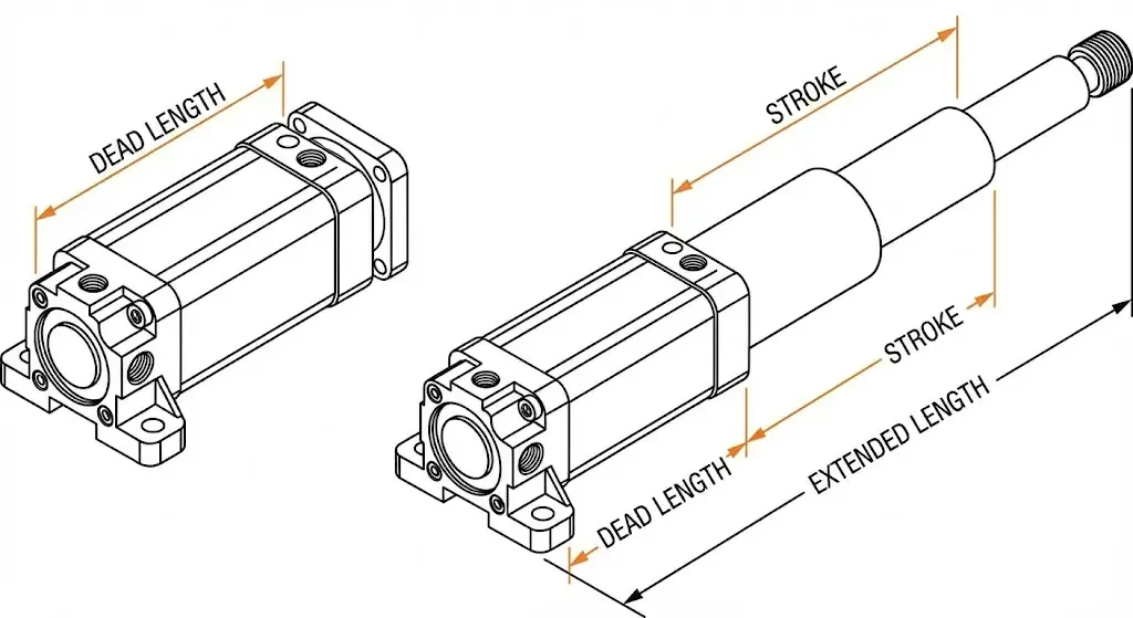
The stroke length of a hydraulic cylinder refers to the linear distance travelled by the output end relative to the cylinder body, from the fully retracted to the fully extended position. For a standard piston-rod type hydraulic cylinder, you can think of it as the distance the piston rod can extend outwards. It describes the distance travelled, not the total length of the piston rod, nor the overall external length of the hydraulic cylinder.
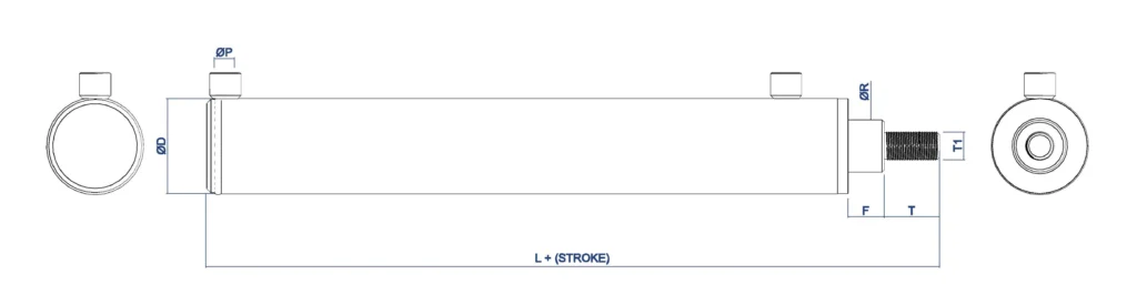
Rod Travel From Fully Retracted to Fully Extended
In a standard single-stage hydraulic cylinder, the piston is connected to the piston rod; therefore, the distance the piston moves within the cylinder is the same as the distance the piston rod moves relative to the cylinder body. For example, a stroke of 200 mm indicates that the piston rod moves approximately 200 mm from the fully retracted to the fully extended position. When the rod is extended and then fully retracted again, the cumulative distance travelled over a complete reciprocating cycle is approximately 400 mm; however, the stroke of the hydraulic cylinder remains 200 mm.
You cannot determine the stroke solely by the length of the rod exposed when it is fully extended. After the piston rod is fully retracted, a portion of the rod end or coupling usually remains exposed outside the cylinder body. Therefore, to determine the stroke, one must compare the change between two positions relative to the same reference point, rather than simply measuring the exposed length once. The stroke is also not necessarily equal to the final distance the load is moved. If the hydraulic cylinder directly pushes a slide along a straight line, the two are usually the same; if the load is driven via a lever, swing arm or pulley, the load displacement also depends on the geometric relationships of the mechanism.
Stroke Length vs. Closed and Extended Length
The closed length is the distance between specified reference points when the hydraulic cylinder is fully retracted; the extended length is the distance between the same set of reference points when the cylinder is fully extended. For common hydraulic cylinders mounted with pins at both ends, the centres of the two mounting holes or pins are typically used as reference points.
Under this measurement method, stroke length = mounting centre distance when fully extended − mounting centre distance when fully retracted. For example, if the retracted centre distance is 600 mm and the extended centre distance is 800 mm, the stroke is 200 mm. The figures given here are merely illustrative of dimensional relationships and do not represent specific product parameters.
When replacing a hydraulic cylinder, you should verify both the stroke and the retracted mounting length. Even if two hydraulic cylinders have the same stroke of 200 mm, their retracted centre-to-centre distances may differ, which could result in the cylinder failing to meet the mechanism’s positional requirements once installed. For flange or trunnion mounting, measurements must be taken using the mounting reference specified in the drawings; the outer end face and the centre of the mounting pins must not be used interchangeably.
Usable Stroke vs. Theoretical Stroke
The theoretical stroke generally refers to the range of movement derived from the design geometry, whilst the usable stroke is the range of movement that the equipment is permitted to utilise under actual operating conditions. However, ‘theoretical stroke’ is not a parameter designation used uniformly by all manufacturers. When you encounter this term, you should confirm whether it refers to the nominal stroke specified in the drawings, the maximum structural stroke, or some other calculated value; the actual delivered dimensions are also subject to the specified stroke tolerances.
Usable stroke may be limited by stop positions, tooling clearances, stop controls and load conditions. For example, suppose a hydraulic cylinder has a nominal stroke of 200 mm, but the equipment control only permits movement between 10 mm and 190 mm; in this case, the usable stroke range for that equipment is 180 mm. This example does not imply that all hydraulic cylinders must have a 10 mm margin at either end; the specific margin should be determined by the equipment design and the manufacturer’s requirements.
A distinction must also be made between end-of-stroke cushioning and stroke limitation. End-of-stroke cushioning is a function that slows the piston as it approaches the end of its stroke; the cushioning section typically still falls within the stroke range and is not an ‘unusable portion’ that must be deducted from the nominal stroke. If your process requires a constant speed throughout the entire stroke, you will need to confirm separately whether the cushioning section is suitable for that process.
If the hydraulic cylinder is fitted with a stop tube, you should also check how the total stroke and net working stroke are specified. Some manufacturers use the ordering rule ‘total stroke = net working stroke + stop tube length’, whereby the total stroke is used to determine structural dimensions and does not equate to the actual distance the output end can travel. When placing an order, you should ask the supplier to clearly confirm the net working stroke available after installation, as well as the working margin that the equipment requires.
How Do You Measure Hydraulic Cylinder Stroke Length?
The method for measuring the stroke of a hydraulic cylinder is as follows: record the axial distance between the same set of reference points when the cylinder is fully retracted and when it is fully extended, then subtract the extended length from the retracted length. The term ‘axial’ here refers to the direction in which the piston rod extends and retracts. It is crucial to use the same reference points for both measurements and to ensure that the hydraulic cylinder has indeed reached both end points of its stroke.
Fully Retract the Cylinder to Its Mechanical Stop
Firstly, following the equipment operating instructions, allow the hydraulic cylinder to return slowly to its fully retracted position. The mechanical stop is the end of the stroke defined by the internal structure of the hydraulic cylinder. The fact that the piston rod has stopped moving does not necessarily mean it has been fully retracted. External stops, limit switches or mechanical interference may cause it to stop prematurely. Do not attempt to confirm the end of stroke by increasing the pressure or repeatedly striking the end.
Before taking any measurements, securely support any loads that may move or fall. Then, shut down the equipment in accordance with the manufacturer’s instructions, isolate the power supply and release any residual pressure. Only approach the cylinder to take a reading once you have confirmed that the mechanism will not move unexpectedly. If the equipment’s design does not permit the hydraulic cylinder to retract fully, this limitation must be recorded; in such cases, the measured distance can only be used to determine the range of motion under the current installation conditions and cannot be directly taken as the full stroke.
Use Consistent Pin-Centre or Mounting Reference Points
For hydraulic cylinders connected at both ends by pins, the distance between the centres of the two pin holes—the ‘pin-centre distance’—can usually be measured. If flange mounting is used, the reference point may be selected as the centre of the rod-end connection relative to the flange mounting surface, in accordance with the installation drawings. Both measurements must use exactly the same reference point; one measurement must not be taken to the centre of the pin hole whilst the other is taken to the outer edge of the mounting lug.
You may first take a photograph, mark the two measurement positions on the photograph, and then record the retracted length. The direction of measurement should align with the axis of the hydraulic cylinder to avoid tilting the tape measure. If the rod-end connector can be adjusted via a threaded mechanism, do not alter its position during measurement; otherwise, the difference between the two lengths will be influenced by the adjustment of the connector.
Extend the Cylinder and Record the Same Measurement
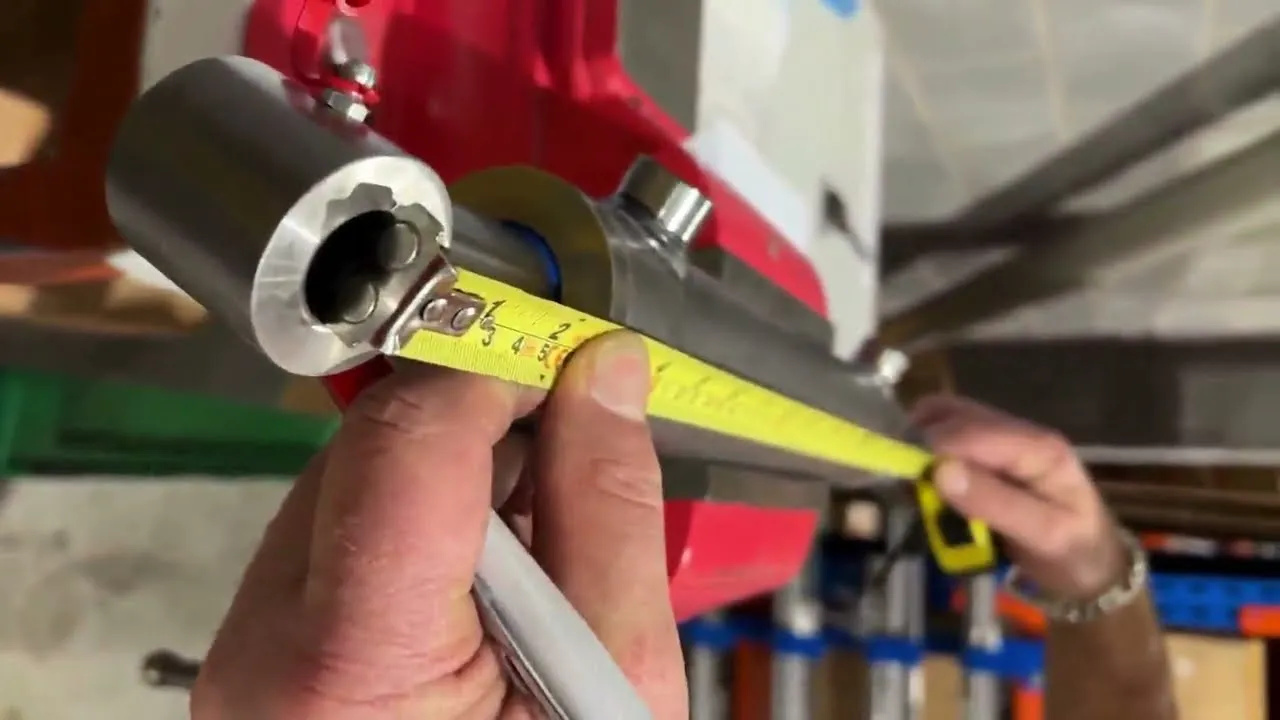
Next, clear the movement range of personnel and obstacles, and, in accordance with the equipment’s permitted operating procedures, allow the hydraulic cylinder to extend slowly to the end of its full stroke. Subsequently, repeat the process of supporting, stopping and isolating the power supply, confirm that the position is stable, and then measure the distance between the same reference points. Do not hold the tape measure with your hand to track the reading whilst the piston rod is moving.
If the hydraulic cylinder stops prematurely due to external limits, load jamming or control settings, this reading represents the currently achievable extension length. To confirm the full stroke, you will also need to check the product drawings or have a qualified person carry out a controlled test. Do not tamper with the equipment’s limit switches to obtain a measurement.
Subtract the Retracted Length from the Extended Length
The calculation formula can be expressed as follows: Stroke = fully extended length − fully retracted length. For example, assuming the centre-to-centre distance of the pin is 620 mm when fully retracted and 870 mm when fully extended, the stroke is 870 − 620 = 250 mm. This represents the distance travelled from the retracted to the extended position in a single movement; there is no need to add the return distance.
It is recommended that you repeat the measurement under the same conditions, whilst retaining the two original lengths. When selecting a replacement hydraulic cylinder, stating merely ‘250 mm stroke’ is insufficient; you should also verify the retracted installation dimensions. If the measurement results differ slightly from the drawings, you should first check the end points, reference positions and the accuracy of the measuring instruments, then make a judgement based on the dimensional tolerances specified by the manufacturer; do not simply round the figure to a standard stroke value.
Measuring Exposed Rod Travel When Mounting Access Is Limited
If the centre of the pin is obscured by a bracket, for standard single-stage piston rod hydraulic cylinders, you can measure the change in exposed rod length. Select a fixed, clearly defined end face on the cylinder head, and then select the same shoulder or connection point on the rod end that moves with the piston rod; measure the axial distance between the two at both fully retracted and fully extended positions. Do not use the lip of a dust seal, which is prone to deformation, as a measurement reference, nor should you mark the piston rod’s coating or clamp metal marking devices onto it.
For example, assuming the reading is 35 mm when retracted and 285 mm when extended, the stroke is 285 − 35 = 250 mm. The exposed length when fully extended must not be taken directly as the stroke, as a section of the rod may still protrude from the cylinder when fully retracted. For multi-stage telescopic hydraulic cylinders, measuring the change in exposed length for only one stage will not yield the total stroke; the complete displacement of the final output end relative to the cylinder body should be measured.
How Do Mounting Styles Affect the Measurement?
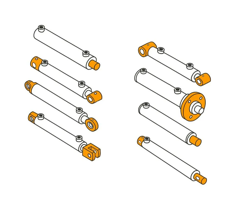
The mounting method primarily affects the choice of measurement reference point; it does not directly alter the stroke of the hydraulic cylinder itself. Regardless of the mounting method used, you will need to measure the displacement of the rod end relative to the cylinder body in the direction of extension and retraction. If the method of subtracting the retracted length from the extended length is used, both measurements must be taken from the same reference position, whilst maintaining the adjustment status of the connecting components.
① Clevis and Cross-Tube Mounts
A clevis mount connects the equipment via a clevis-shaped coupling and a pin; a cross-tube mount, on the other hand, involves a pin passing through a transverse tube bore. For common hydraulic cylinders with this type of connection at both ends, the centres of the two pin bores are typically used as the measurement reference. Record the centre-to-centre distance when the cylinder is fully retracted and fully extended respectively; the difference between the two is the stroke.
You should measure the centre-to-centre distance between the pin holes, not the distance between the outer edges of the clevis or cross-tube. The external dimensions of different mounting fittings may vary, and the outer edge lengths are not suitable for direct use in replacement selection. If the pin obstructs the hole, the centre position should be determined based on the pin’s diameter and clearly visible edges. If the pin holes are significantly worn and the centre position is difficult to determine accurately, you should consult the original installation drawing as a priority.
Hydraulic cylinders of this type may also oscillate during extension and retraction. When measuring, the distance should be read along the cylinder’s own axis; the horizontal distance travelled by the rod end relative to the ground must not be used as a substitute for the stroke.
② Flange and Foot Mounts
Flange mounting utilises a mounting plate with bolt holes to secure the cylinder body; foot mounting is secured via feet located beneath or on the side of the cylinder body. As these typically lack a centre pin at the cylinder base for measurement, you must select a fixed reference point based on the installation drawing and then measure the axial distance from that reference point to the corresponding reference point on the rod end. Manufacturers provide dimensioned drawings for different mounting configurations; the relevant drawings should be used when selecting a model.
For flange mounting, the flange mounting surface specified in the drawing may be used; for foot mounting, a clear end face of the cylinder body or the position of the mounting hole centre on the axial line may be used. The foot mounting holes are usually located below the piston rod axis; the diagonal distance from the centre of the hole to the end of the rod must not be used directly to calculate the stroke difference. You must measure the distance along the direction of piston rod extension and retraction; otherwise, the difference in height will introduce errors.
If the measurement is for the purpose of purchasing a replacement cylinder, the flange position or the spacing of the foot mounting holes should also be recorded separately. Even if two cylinders have the same stroke, they may not be interchangeable due to differences in these mounting dimensions.
③ Trunnion Mounts
A trunnion mount supports a hydraulic cylinder via coaxial journals projecting from both sides of the cylinder body, allowing it to pivot about the trunnions. When measuring the installation length, it is usually necessary to take the axis of rotation of the trunnions as the reference point and then determine the axial distance from this to the centre of the rod end connection. Do not treat the outer edge of the trunnion or the edge of the mounting housing as the centre of rotation.
The most common source of confusion here is the position of the trunnions. The front, rear and centre trunnions are located at different points on the cylinder body; consequently, hydraulic cylinders with the same stroke may have different retraction distances from the trunnions to the rod end. You should specify the trunnion positions in your measurement records and mark the reference points, rather than simply noting an ‘overall length’ without any reference to a baseline.
If the hydraulic cylinder changes its angle of inclination during measurement, always use the relative position between the cylinder body and the rod end as the reference. The movement path of the rod end on the equipment includes the effect of cylinder sway and cannot be directly taken as the piston rod stroke.
④ Threaded Rod Ends and Adjustable Clevises
Threaded rod ends allow you to install connecting components such as clevises and rod-end joints; adjustable clevises allow the connection position to be adjusted by changing the thread engagement depth. This adjustment alters the installation length but does not increase the mechanical stroke inside the hydraulic cylinder. The position of the connecting components should be recorded before measurement, and care must be taken to ensure that no rotation or loosening has occurred between the two readings.
For example, suppose a hydraulic cylinder has a retraction centre-to-centre distance of 600 mm and an extension centre-to-centre distance of 850 mm; the stroke is 850 − 600 = 250 mm. If, within the permitted adjustment range, the rod-end connection position is moved outwards by 10 mm, the two centre distances will become 610 mm and 860 mm respectively, with the difference remaining at 250 mm. This is merely a hypothetical example illustrating the dimensional relationship and does not imply that all fork ears permit an adjustment of 10 mm.
How Do You Determine the Required Stroke for a Machine?
To determine the required stroke of the hydraulic cylinder for the machine, you should first identify the maximum and minimum installation lengths of the hydraulic cylinder throughout the entire motion cycle, and then determine the necessary allowance based on dimensional tolerances, stopping methods and installation space. The stroke must not be selected solely on the basis of how high the platform rises or how far the door panel opens, as the connecting rods and pivot shafts will alter the relationship between the movement of the hydraulic cylinder and that of the load.
1. Measure the Mechanism at Both End Positions
Firstly, you need to determine the two working positions actually required by the machine, such as when the flap is fully closed and when it is opened to a specified angle. For a hydraulic cylinder connected by pins at both ends, measure the distance between the centres of the two planned mounting pins at each of these positions. If the hydraulic cylinder has been removed, the mechanism must be secured using reliable supports or jigs to prevent it from falling freely.
Assuming the centre-to-centre distances at the two operating positions are 520 mm and 760 mm respectively, and that the centre-to-centre distance increases in one direction throughout the movement, the required displacement of the hydraulic cylinder is 760 − 520 = 240 mm. This is merely the required working displacement and does not yet include the finalised clearances at both ends.
When selecting the stroke, one must also verify the installed length of the hydraulic cylinder when fully retracted. Even if a hydraulic cylinder has a stroke of 240 mm, if the centre-to-centre distance when fully retracted exceeds 520 mm, the mechanism will still be unable to reach the required closed position.
2. Account for Linkage Geometry and Changing Leverage
A linkage mechanism is a structure that transmits motion via connecting rods and pivots. For hydraulic cylinders that directly drive a slide along a straight line, the slide displacement typically corresponds to the piston rod displacement. However, in tilting platforms, lifting arms or scissor mechanisms, the relationship between the two is not usually one-to-one. You need to calculate how the length of the hydraulic cylinder varies with movement, based on the position of the mounting points and the angles of the mechanism.
In such cases, it is also necessary to examine the lever arm—that is, the perpendicular distance from the pivot to the line of action of the hydraulic cylinder’s force. The shorter the lever arm, the greater the hydraulic cylinder thrust required to generate the same rotational torque. Therefore, the fact that the stroke covers the range of motion does not mean the hydraulic cylinder can provide sufficient thrust at every position. Particularly near ‘dead centres’—where the line of action of the force is close to passing through the pivot—the required thrust may increase significantly.
It is recommended that you use a CAD motion model or calculate the length and forces segment by segment based on the mounting point coordinates. For complex mechanisms, the maximum or minimum mounting distance may occur at an intermediate position; therefore, it is not sufficient to simply subtract the distance between the two end positions. In such cases, the following formula should be used: Required working displacement = maximum mounting length within the full range of motion − minimum mounting length.
3. Allow for Tolerances Without Using the Cylinder as a Hard Stop
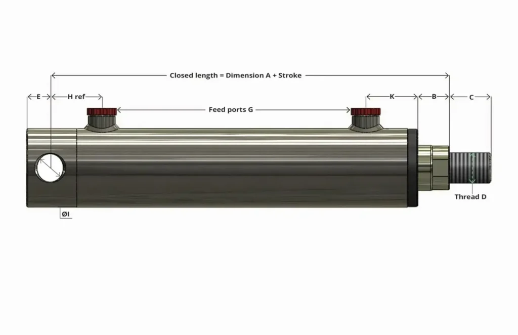
Tolerances are the permissible deviations in dimensions. There may be tolerances in the position of mounting holes, the length of connecting components and the stroke of the hydraulic cylinder; furthermore, loads may cause elastic deformation of the structure. You need to take all these factors into account to ensure that, when the machine reaches the required position, the hydraulic cylinder remains within its design-permitted range of motion. There is no fixed margin applicable to all machines, nor should a uniform percentage be added across the board.
Continuing with the previous assumption, if an assessment of dimensions and stopping distances determines that a margin of 5 mm is required at both the retracted and extended ends, then the nominal stroke must be at least 240 + 5 + 5 = 250 mm. With the corresponding ideal installation dimensions, the centre-to-centre distance when fully retracted would be 515 mm, and when fully extended, 765 mm, ensuring that the machine’s working range of 520–760 mm falls within this. These figures are provided solely to illustrate the calculation; actual manufacturing tolerances must also be verified.
Do not assume that the piston will repeatedly strike the internal end stops to halt the machine. Hard stops are structural elements that prevent the mechanism from continuing its motion through physical contact; they should be designed according to actual loads and impact forces, and supplemented with appropriate deceleration control. Hydraulic cylinder buffering can reduce speed as the stroke nears its end, but it is still necessary to verify that the load and speed are within the cylinder’s capacity; if the machine stops prematurely outside the buffering zone, the internal buffering cannot be relied upon to function.
4. Verify Clearance Throughout the Entire Motion Path
Once the candidate stroke has been determined, you must check for clearance throughout the entire motion path, including between the cylinder barrel and the frame, the rod end and the bracket, the hydraulic port fittings and adjacent components, and whether the hose is pulled taut, pinched or excessively kinked during oscillation. The absence of collisions at the two end points does not guarantee that there is sufficient space at intermediate positions.
For swing-mounted installations, you should also check whether the fork ears and rod-end joints reach their rotational limits. If the connecting components strike the bracket first, the hydraulic cylinder may be subjected to lateral forces—that is, forces acting off-axis to the piston rod. In this case, the mounting position or connection structure should be adjusted; you must not rely on increasing pressure to continue the stroke.
You may first carry out a full-stroke interference check in CAD, followed by verification at low speed in accordance with the equipment commissioning procedure. Ultimately, it must be confirmed that: the machine can reach both working positions without interference along the way, the connecting components have sufficient range of motion, and the actual position after stopping still retains the required stroke margin.
What Happens If the Stroke Is Too Short or Too Long?
If the stroke of a hydraulic cylinder is too short, the machine will be unable to reach its target position; if the stroke is too long, it may result in overtravel, collisions with components, and an increased risk of piston rod instability during extension under pressure. However, damage is not determined by the stroke figure alone. You must also check the installation length, the range of motion of the mechanism, the stopping method and the load. When selecting a cylinder, ensure that it covers the required working displacement and allows for a calculated margin of safety.
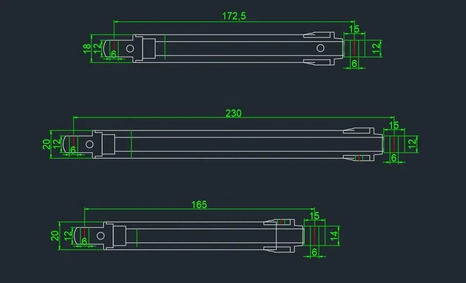
Incomplete Machine Travel
The most obvious indication of insufficient stroke is when the hydraulic cylinder has fully extended or retracted, yet the machine has not completed its movement. For example, a clamping device may fail to open fully, a tilting plate may not reach the required angle, or a material-feeding mechanism may be unable to move the workpiece to the specified position. For link mechanisms, you should compare the change in distance between the two mounting points of the hydraulic cylinder; the required stroke should not be determined solely by the distance the workpiece travels.
Suppose a mechanism requires a hydraulic cylinder to provide 240 mm of working displacement, but the cylinder you have selected has a stroke of only 220 mm; in this case, assuming the mounting geometry remains unchanged, there will be a shortfall of 20 mm in displacement. Increasing the pressure can only alter the force available; it cannot increase the mechanical stroke. Unscrewing the rod-end lugs slightly merely changes the mounting length; whilst this may improve the position at one end point, it may prevent the other end point from being reached.
However, a machine failing to reach its end position is not necessarily due to an insufficient stroke length. You should first confirm whether the piston rod has actually reached the internal end of its stroke. If it has not, check for external stops, control settings or mechanical obstructions, rather than immediately replacing the hydraulic cylinder with a longer one.
Bottoming-Out and End-Cap Damage
‘Bottoming-out’ refers to the piston reaching the internal mechanical end point and coming into contact with the end-cap structure. When the stroke is insufficient, the machine may still be demanding further movement, whilst the piston has already reached its end point. If the speed is high prior to stopping, the inertia of the moving load will create an impact, which may damage the end cap, the piston connection or the mounting components. The purpose of hydraulic cushioning is to reduce speed as the end point is approached, thereby minimising this impact.
Reaching the end of the stroke under normal conditions does not necessarily mean that the end cap will be damaged. Some hydraulic cylinders are designed to operate over their full stroke under specified load, speed and cushioning conditions. What must truly be avoided are unchecked high-speed impacts and the use of the internal end stop as a shock stop for the entire machine. If the equipment repeatedly experiences end-of-stroke impacts, noticeable vibration or pressure spikes at the end of the stroke, the stop position and deceleration settings should be checked, rather than simply increasing the system pressure.
Overtravel, Interference and Seal Damage
Overtravel provides the mechanism with a range of motion exceeding that required. If the stop control is not appropriately limited, the machine may overshoot the target position, resulting in the connecting rod colliding with the frame, the connecting components reaching their rotational limits, or the hose becoming taut. The term ‘overtravel’ here refers to the machine exceeding its permissible operating range; it does not imply that the piston can normally pass beyond the mechanical end point of the hydraulic cylinder itself.
Seal damage usually occurs indirectly. For example, if a mechanism continues to be driven after striking an obstacle, the piston rod may be subjected to lateral forces—that is, forces acting at an angle to the rod’s axis. The resulting uneven wear, surface scuffing or damage to the guide surfaces will further compromise the seals.
Hydraulic cylinders with a longer stroke may be used to their full extent, provided that the installation dimensions, position control and stopping measures have been verified. You should inspect the entire travel path and confirm that the actual position after stopping remains within the permitted range. If the machine stops before the hydraulic cylinder enters its internal buffer zone, you cannot rely on the internal buffer to absorb the impact of this stop.
Added Risk of Rod Buckling Due to Excessive Length
When the piston rod extends and pushes against a load, it is subjected to axial compression. If the rod is too long and inadequately supported, ‘buckling’ may occur, whereby it suddenly bends sideways under pressure. The fact that a hydraulic cylinder can generate sufficient thrust does not necessarily mean that the extended piston rod can safely withstand this force; manufacturers therefore carry out separate buckling resistance checks. Assuming the Euler elastic buckling model applies, and with the rod diameter and other conditions remaining constant, the effective buckling length doubles, whilst the theoretical critical load is reduced to a quarter of its original value. The effective buckling length is a calculated length that takes into account supports and mounting constraints; it cannot be directly equated with the nominal stroke.
Consequently, if increasing the stroke results in a longer actual compressed length, you should re-verify the rod diameter, mounting method and the compressive load at the maximum extended position. Even if only a portion of a longer hydraulic cylinder’s stroke is utilised, verification must be based on the actual structure rather than the displacement alone. For operating conditions where axial tensile forces are constantly present, this risk of compression buckling is not usually the primary limiting factor; however, it is still necessary to confirm whether there are any compression phases during the working cycle.
Which Specifications Must Be Checked With Stroke?
When determining the stroke of a hydraulic cylinder, you must also verify the retracted installation length, the cylinder bore and rod diameter, the mounting method and port orientation, buffering and position detection, as well as the load-bearing capacity at maximum extension. The stroke merely indicates how far the piston rod can move; it does not, on its own, prove that the hydraulic cylinder will fit, be able to apply the required force, or operate stably.
Retracted Pin-to-Pin Length
The retracted pin-to-pin length is the distance between the centres of the connecting pin holes at both ends when the hydraulic cylinder is fully retracted. For standard single-stage hydraulic cylinders connected by pins at both ends, provided the position of the connecting fittings remains unchanged, the fully extended centre-to-centre distance = the fully retracted centre-to-centre distance + the stroke. You must verify these two dimensions against the installation position required by the machine.
For example, suppose two hydraulic cylinders both have a stroke of 250 mm, but their retracted centre-to-centre distances are 500 mm and 550 mm respectively; in that case, their fully extended centre-to-centre distances would be 750 mm and 800 mm respectively. If the machine’s required mounting distance range is 500–750 mm, the second cylinder would be unable to cover the shortest position. This hypothetical example illustrates that identical stroke does not necessarily mean direct interchangeability.
If you are using flange or foot mounting, you should verify the dimensions against the mounting surfaces or mounting hole positions specified in the drawings, rather than simply applying the centre-to-centre distance of the pins.
Bore and Rod Diameter
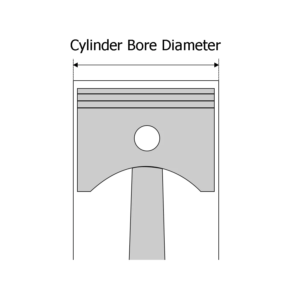
The bore diameter is the internal diameter of the cylinder barrel and determines the area over which the piston is subjected to pressure; the rod diameter is the diameter of the piston rod, which affects the load-bearing capacity of the rod and also influences the effective pressure area during retraction in a standard single-rod hydraulic cylinder. You should select the bore diameter based on the required thrust or pulling force and the actual available pressure, then verify the rod diameter in conjunction with the stroke, mounting method and load conditions.
For example, assuming back pressure and friction are negligible, a standard double-acting single-rod hydraulic cylinder with a bore diameter of 63 mm and a rod diameter of 40 mm, operating at a supply pressure of 16 MPa in both directions of movement, would have a theoretical extension thrust of approximately 49.9 kN and a retraction pull force of approximately 29.8 kN. The tensile force is smaller because the area under compression on the retraction side must be reduced by the cross-sectional area of the piston rod. This is a theoretical calculation example and not a measured product value.
Mounting Style and Port Orientation
The mounting style determines how the hydraulic cylinder is connected to the machine and whether it can swing during operation. You need to check the pin hole diameter, yoke width, flange bolt centre distance or trunnion position, and ensure that the connecting components will not become jammed throughout the entire range of motion. For mechanisms requiring swing movement, you must not simply replace the original articulated mounting with a rigid fixed mounting merely because the dimensions are similar.
Port orientation refers to the direction in which the inlet and outlet ports face relative to the cylinder body. Even if the thread specifications of the ports are identical, their orientation relative to the frame may prevent the fitting of connectors or cause the hose to be pinched during extension and retraction. It is recommended that you indicate the viewing direction, port positions and the space required for fittings on the installation drawing, whilst also ensuring that the cushioning adjustment position is accessible.
Cushioning and Position Sensing
Cushioning is a function that slows the piston down as it approaches the end of its stroke, typically by restricting the outflow of oil. For mechanisms operating at high speeds or with significant moving mass, you should provide the supplier with details of the load, speed as the piston approaches the end of its stroke, installation orientation and operating frequency, to enable them to assess the cushioning capacity. The availability of a cushioning option does not guarantee that it can absorb the stopping impact of any load. If the machine utilises only a portion of the stroke, you must also confirm whether the piston actually enters the cushioning zone before coming to a stop.
Position sensing is used to inform the control system of the piston rod’s location. Limit switches typically only determine whether a specific position has been reached; whereas continuous displacement sensors provide position feedback across the entire measurement range. If multiple intermediate stopping points are required, you should verify the sensor’s measurement range, accuracy and compatibility with the control system. The sensor itself does not stop the hydraulic cylinder; the actual stopping position also depends on valve response, load inertia and deceleration control, so the trigger position must not be taken directly as the final stopping position.
Column Load at Maximum Extension
The term ‘column load’ here refers to the compressive load borne by the piston rod along its axis. When a long-stroke hydraulic cylinder extends to push a load, the piston rod may buckle under compression, i.e. become unstable and bend sideways. Therefore, the maximum hydraulic thrust and the permissible compressive load must be verified separately; one must not rely solely on the rated pressure or thrust table. You should provide the manufacturer with the maximum working extension position, rod diameter, mounting constraints, external guidance and peak compressive load, and then use the appropriate anti-buckling charts or calculation methods to verify the design.
Hydraulic Cylinder Stroke Measurement Checklist
Reliable stroke measurement requires confirmation of four key points: that the equipment is in a safe condition, that the same reference point is used for both measurements, that the end points of extension and retraction have been verified, and that the results comply with the dimensional definitions and tolerance requirements for the relevant product. You should retain the original readings for the retracted and extended lengths, rather than simply recording the difference between them, to facilitate subsequent product selection and verification.
① Isolate, Support and Depressurise the Equipment
Before approaching a hydraulic cylinder to take manual measurements, isolate the power supply in accordance with the equipment specifications and prevent accidental start-up. For mechanisms that may drop, tip over or slide, they must first be supported using suitable mechanical supports or locking devices before releasing the relevant hydraulic pressure. Do not rely solely on the hydraulic cylinder or closed valves to maintain the load position.
Shutting down the hydraulic pump does not mean that all areas are pressure-free. Accumulators—devices that store hydraulic energy—and oil chambers sealed by valves may retain pressure. These must be handled in accordance with the equipment’s specified pressure relief and verification procedures; do not test for residual pressure by loosening pipe fittings. Manufacturers also explicitly require that hydraulic pipe connections be loosened only after pressure has been relieved.
When switching from the retracted position to the extended position, personnel and measuring instruments must first be removed, after which a qualified person must carry out the operation in a controlled manner in accordance with the equipment procedures. Upon reaching the new measurement position, the support, isolation and pressure relief verification procedures must be repeated. Do not reach in to take measurements whilst the mechanism is in motion, nor should the equipment be started directly after removing the supports without due care.
② Record Units and Reference Points
Measurement records must clearly specify whether millimetres or inches are used and indicate the reference points. For example, stating ‘When fully retracted, the centre-to-centre distance between the two end pin holes is 620 mm’ is clearer than simply writing ‘Length 620’. 1 inch = 25.4 mm; therefore, a 10-inch stroke equals 254 mm and must not be directly substituted as 250 mm.
Reference points are the fixed positions used for each measurement. For pin connections, the centres of the pin holes are typically used; for flange mountings, the mounting surface and a single rod-end reference point specified in the drawings should be selected. You may mark these positions on photographs whilst also recording the settings of the adjustable lugs. Both readings must be taken along the extension and retraction direction of the hydraulic cylinder; do not measure the centre-to-centre distance in one instance and the outer edge distance in another, nor adjust the rod-end fittings midway through the process.
③ Measure Twice at Both End Positions
After confirming that the tape measure has been fully retracted, take two independent readings using the same measuring instrument; after it has been fully extended, take two readings in the same manner. When retaking measurements, reposition the measuring instrument to check whether the tape measure is tilted, whether the reference point has shifted, and whether the mechanism remains stable. Consistency between the two readings merely indicates good measurement repeatability; it does not, on its own, prove that the end points have been selected correctly.
Assuming the retracted length is 620 mm and the extended length is 870 mm, then stroke = 870 − 620 = 250 mm. This is a calculation example and not actual measured data for any specific product. If there is a significant discrepancy between the two measurements, the cause should be investigated first; do not simply take the average to mask the problem. A tape measure can be used for preliminary identification of specifications; however, to determine minor dimensional deviations, measuring instruments and methods with suitable accuracy should be used.
The fact that an external stop or limit switch causes the machine to stop does not necessarily mean that the hydraulic cylinder has reached the end of its full stroke. If it is not possible to confirm full extension or retraction, the result should be labelled as the ‘measured range of motion under current installation conditions’; the full stroke should then be confirmed via product drawings or controlled testing. Pressure must not be increased arbitrarily to force the mechanism into position.
④ Confirm Manufacturer Stroke Increments and Tolerances
Stroke increments refer to the intervals between the available stroke lengths for a particular product series; stroke tolerances refer to the permissible deviations of the actual stroke from the nominal value. The two are not the same, and there are no standard values applicable to all hydraulic cylinders. You must confirm with the manufacturer which stroke lengths are available for that series, whether customisation is supported, and the corresponding tolerance requirements. The actual stroke of a hydraulic cylinder is affected by the cumulative dimensional deviations of components such as the piston, end caps and cylinder barrel; therefore, product catalogues usually specify stroke tolerances separately.
Frequently Asked Questions About Hydraulic Cylinder Stroke
Is stroke length the same as rod length?
No. Stroke is the distance travelled by the piston rod from fully retracted to fully extended, whilst rod length refers to the length of the piston rod component itself. Part of the piston rod is used for internal connections and support, so you cannot use the total length of the rod as a substitute for the stroke. The exposed rod length when fully extended does not necessarily equal the stroke, as a section of the rod may still protrude from the cylinder when fully retracted.
Can You Use a Cylinder With a Longer Stroke?
Yes, but you must ensure that the mounting dimensions, available space and stop controls are all suitable. You may only utilise part of the longer stroke, but a hydraulic cylinder with a longer stroke may have a different retraction length and could cause the mechanism to exceed its permitted limits. Before replacement, you should check both end positions and the entire travel path, and confirm the load-bearing capacity at the maximum extended position.
Does Stroke Length Affect Cylinder Force?
Stroke length alone does not directly determine the theoretical hydraulic thrust; pressure and the effective compression area are the primary factors. For a standard single-stage hydraulic cylinder, under conditions where the pressure, bore diameter and rod diameter remain the same, increasing the stroke length will not automatically increase the thrust or pulling force. When back pressure and friction are disregarded, the theoretical force can be calculated as ‘pressure × effective pressure area’. However, an increase in the compressed length after extension may reduce the piston rod’s resistance to buckling. Buckling refers to the instability caused by the rod bending sideways under pressure. Therefore, the fact that the theoretical thrust is the same does not mean that the permissible load is the same. For multi-stage telescopic cylinders, the thrust must also be assessed separately for each stage based on its effective area.
How Is Telescopic Cylinder Stroke Measured?
The total stroke of a telescopic hydraulic cylinder is the axial displacement of the final output end relative to the cylinder body, measured between the fully retracted and fully extended positions of all stages. You should measure both states using the same mounting reference point, then calculate: Total stroke = Fully extended length − Fully retracted length. Do not measure only the exposed length of the thinnest stage.
For common multi-stage sleeve configurations, the total stroke is also equal to the sum of the effective extension strokes of each stage relative to the outer sleeve. For example, assuming the strokes of three stages are 300, 280 and 260 mm respectively, the total stroke is 840 mm. The strokes of each stage are not necessarily the same, so you cannot simply multiply the stroke of a single stage by the number of stages; if machine limits prevent a particular stage from extending fully, what you measure is only the currently available range of motion.
Choosing a Trusted Hydraulic Cylinder Manufacturer
From standard hydraulic cylinders to custom solutions, we help you improve equipment performance, delivery reliability, and batch consistency
Explore Rivmate Cases

Hey There, I'm Melody!
We are a hydraulic cylinder manufacturer. For over 20 years, we have focused on producing reliable hydraulic cylinders. Need a hydraulic cylinder solution? Feel free to contact us.