
Home / What Is a Hydraulic Cylinder? Parts, Types, and Uses
What Is a Hydraulic Cylinder? Parts, Types, and Uses
- Author: GY Hydraulic
- 20+ Years of Manufacturing
A hydraulic cylinder is a mechanical actuator that converts the pressure energy of hydraulic fluid into linear motion and thrust or pulling force. Simply put, pressurized hydraulic fluid enters the cylinder, pushing the piston and causing the piston rod—which is connected to the piston—to extend or retract, thereby driving the equipment to perform actions such as lifting, pushing, or clamping. Hydraulic cylinders are essential for operations such as raising the boom on an excavator or lifting the bed of a dump truck.
If you are researching or purchasing hydraulic cylinders, understanding their structure and operating principles will make it easier to determine which product is suitable for your equipment. This article will explain the functions of the cylinder barrel, piston, piston rod, and seals; clarify the differences between single-acting, double-acting, and multi-stage telescoping hydraulic cylinders; and, by examining common applications, help you understand how load, stroke, and operating pressure influence your selection.
Table of Contents
Hydraulic Cylinders Explained in Simple Terms
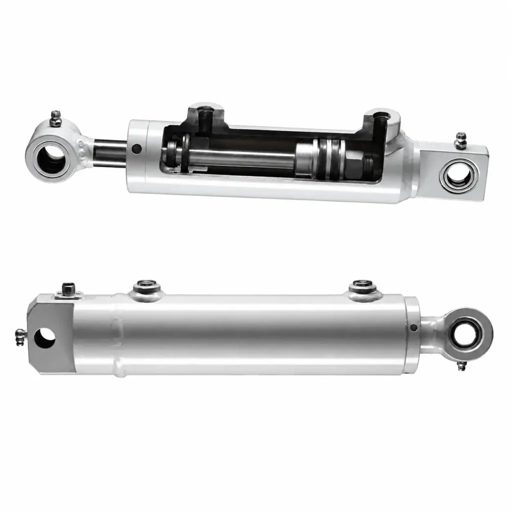
A hydraulic cylinder is a device that uses pressurized hydraulic fluid to generate linear motion and thrust or pulling force; it is also commonly referred to as a hydraulic cylinder. You can think of it as the component in a machine responsible for “extending, retracting, and applying force.” For example, the hydraulic cylinders on an excavator extend and retract to drive the linkage, allowing the boom to lift or the bucket to rotate. The hydraulic cylinder itself primarily performs linear motion, while the rotation of the equipment is achieved by the linkage.
How Does It Produce Force?
Take a common piston-type hydraulic cylinder as an example: the cylinder barrel contains a piston connected to a piston rod that extends outside the cylinder. When hydraulic fluid enters one chamber, the hydraulic pressure acts on the effective area of the piston, generating thrust; during operation, the fluid on the other side must have a suitable outlet channel. The cylinder itself does not generate power; it relies on a hydraulic system to supply fluid, with control valves managing the direction and speed of movement.
You can start by remembering two relationships: Pressure and effective area together determine the theoretical output force, while flow rate and effective area together determine the speed of movement. Flow rate refers to the volume of fluid entering the cylinder per unit of time. For example, at the same pressure, increasing the piston’s effective area can increase the theoretical thrust; however, if the flow rate remains constant, the speed of movement will decrease. Therefore, the notion that “the larger the cylinder, the faster it moves” is a common misconception.
When Is a Hydraulic Cylinder Useful?
If your equipment needs to generate significant linear thrust or pulling force within a limited space, you may want to consider a hydraulic cylinder—for example, to lift a vehicle body, clamp a workpiece, or move a robotic arm. If continuous rotation is required, you should generally evaluate hydraulic motors or electric motors; for light-load, short-stroke applications, you can also compare pneumatic cylinders or electric linear actuators. Especially when your equipment lacks a ready-made hydraulic system, you’ll also need to factor in the cost and maintenance requirements of adding pumps, valves, and piping.
What Should You Check First?
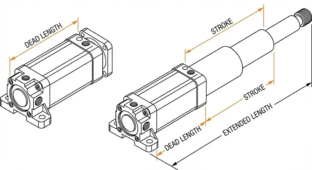
Before beginning the selection process, clearly define the required thrust or pulling force, the distance to be moved, and the time required to complete the motion. The distance moved is called the stroke.
For example, when lifting a heavy object, you cannot simply use the object’s weight as the required thrust for the hydraulic cylinder; if the cylinder is mounted at an angle or lifts via a linkage, the force will vary depending on the mechanism’s position. Provide the supplier with both the load specifications and an installation diagram so they can accurately determine the required dimensions and operating pressure—rather than placing an order based solely on the cylinder appearing “sturdy” at first glance.
How a Hydraulic Cylinder Converts Pressure Into Linear Force
A hydraulic cylinder generates thrust or tensile force along the cylinder barrel by applying hydraulic pressure to the effective area of the piston. The effective area is the surface area under pressure that converts hydraulic pressure into axial force. When the resultant force created by the hydraulic pressure on both sides is sufficient to overcome the load and friction, the piston drives the piston rod to move; if the load prevents movement, the cylinder can still apply force while remaining stationary.
Pressure Acts on the Piston Area
Under simplified conditions where pressure on the opposite side and friction are neglected, the theoretical output force equals pressure multiplied by the effective area, i.e., F = P × A. This means that at the same pressure, the larger the area subjected to pressure, the greater the theoretical output force. When pressure is measured in MPa and area in mm², the product yields a force in N (Newtons). Manufacturers’ hydraulic cylinder calculation data also use this fundamental relationship.
For example, assume a cylinder bore of 50 mm and a rod-side oil pressure of 10 MPa. The piston area is π × 50² ÷ 4, which is approximately 1,963 mm²; therefore, the theoretical extension thrust is approximately 19.6 kN, or 19,600 N. Here, the cylinder bore refers to the inner diameter of the cylinder barrel, not the outer diameter. This is a calculation example used to explain the principle; it is not the result of actual product testing and cannot be directly used as the equipment’s rated lifting capacity.
Extension and Retraction Use Different Areas
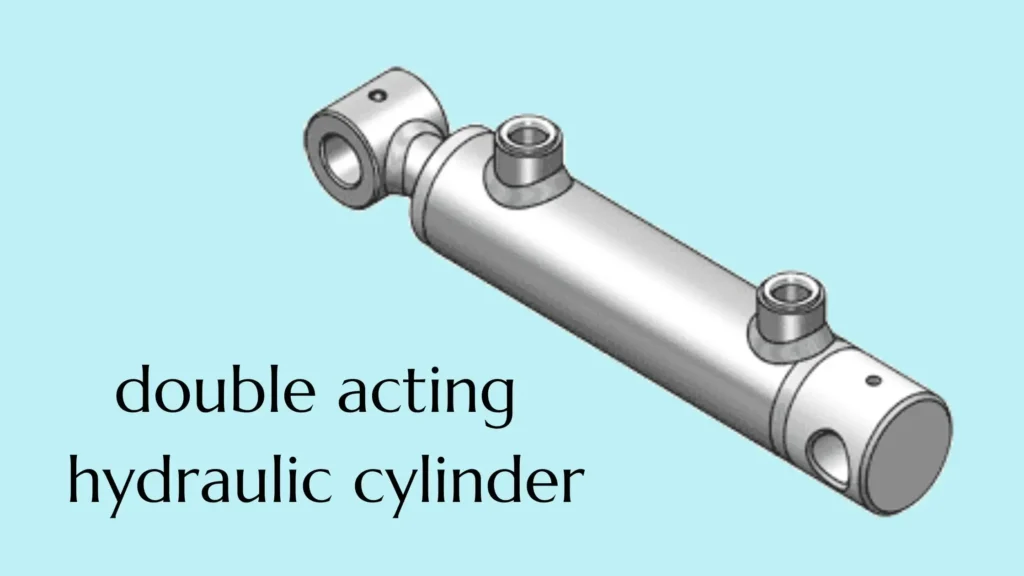
For a common single-rod, double-acting hydraulic cylinder, “double-acting” means that both extension and retraction are hydraulically driven. During extension, the oil pressure acts on the entire area of the piston; during retraction, the piston rod occupies a portion of that area, so the effective area is “the piston area minus the cross-sectional area of the piston rod.” Assuming the supply pressure is constant and ignoring return pressure and friction, the retraction force is less than the extension thrust.
Continuing with the assumptions above, if the piston rod diameter is 30 mm, the effective area during retraction is approximately 1,257 mm², and the theoretical pulling force is approximately 12.6 kN. Therefore, if your equipment primarily relies on retraction to perform its work, you should select the cylinder based on the retraction pulling force and not directly use the extension thrust listed in the catalog. This difference in area does not apply to double-rod configurations where the piston rod diameters are the same at both ends.
Back Pressure and Friction Reduce Available Force
In actual hydraulic cylinders, there is typically pressure on the return side, known as back pressure, which offsets a portion of the driving force. Taking extension as an example, the force available to overcome the load is calculated by subtracting the reverse force caused by back pressure on the rod side and the friction resistance from the thrust generated by the pressure on the non-rod side. When the equipment accelerates, additional force is also required to accelerate the moving parts.
Therefore, you should use the actual working pressure at the cylinder port to evaluate the output force, rather than directly applying the pump’s maximum pressure or the cylinder’s maximum allowable pressure. When submitting load requirements to a supplier, be sure to specify the return flow conditions, direction of motion, and mounting angle to determine whether the theoretical thrust is sufficient.
Force and Speed Are Different
Pressure and cross-sectional area determine the theoretical force, while flow rate and cross-sectional area determine the theoretical speed. Flow rate is the volume of fluid entering the cylinder per unit time; assuming no leakage, speed equals flow rate divided by the effective cross-sectional area. Therefore, at the same supply flow rate, increasing the cylinder bore diameter can increase thrust but will reduce the extension speed. You need to specify both “how much force” and “how quickly the motion should be completed”; simply using a larger cylinder will not solve all problems.
Main Parts of a Hydraulic Cylinder and Their Functions
Common hydraulic cylinders primarily consist of a cylinder barrel, piston, piston rod, end caps, guide components, seals, and hydraulic ports. Together, these components bear hydraulic pressure, transmit force, guide motion, and control leakage. Below, we’ll use a common single-rod, double-acting hydraulic cylinder as an example—a design in which the piston rod extends from only one end, and both extension and retraction are hydraulically driven.
① Cylinder Barrel
The cylinder barrel is the pressure-bearing housing that contains the piston and hydraulic fluid; its inner surface also serves as the contact surface for the piston seals. The bore diameter refers to the inner diameter of the cylinder barrel and affects the piston’s pressure-bearing area and output force; the outer diameter, however, cannot be directly used to calculate thrust. When selecting a cylinder, you must verify both the bore diameter and the allowable working pressure; you cannot assume the cylinder has sufficient pressure-bearing capacity simply because the barrel wall appears thick.
② Piston
The piston is located inside the cylinder barrel, connected to the piston rod, and works in conjunction with the piston seals to separate the two chambers. Hydraulic pressure on both sides acts on their respective effective areas, generating a resultant force that drives the piston. When the piston seals are damaged, fluid may leak between the two chambers—a phenomenon known as internal leakage. This issue does not necessarily manifest as external fluid leakage. Therefore, if the equipment lacks sufficient thrust, do not rely solely on whether the cylinder exterior is dry; you must also check the system pressure and assess the internal leakage situation.
③ Piston Rod
The piston rod transmits the force generated by the piston to the external mechanism, and its surface repeatedly passes through seals and guide components. For example, scratches or rust on the rod surface may accelerate seal wear and cause oil leakage. You should select the rod diameter and surface treatment based on the load, extension length, and environment; for long-stroke compression applications, you must also check the rod’s buckling resistance—that is, its ability to resist buckling instability under compression.
④ Cylinder Head and End Cap
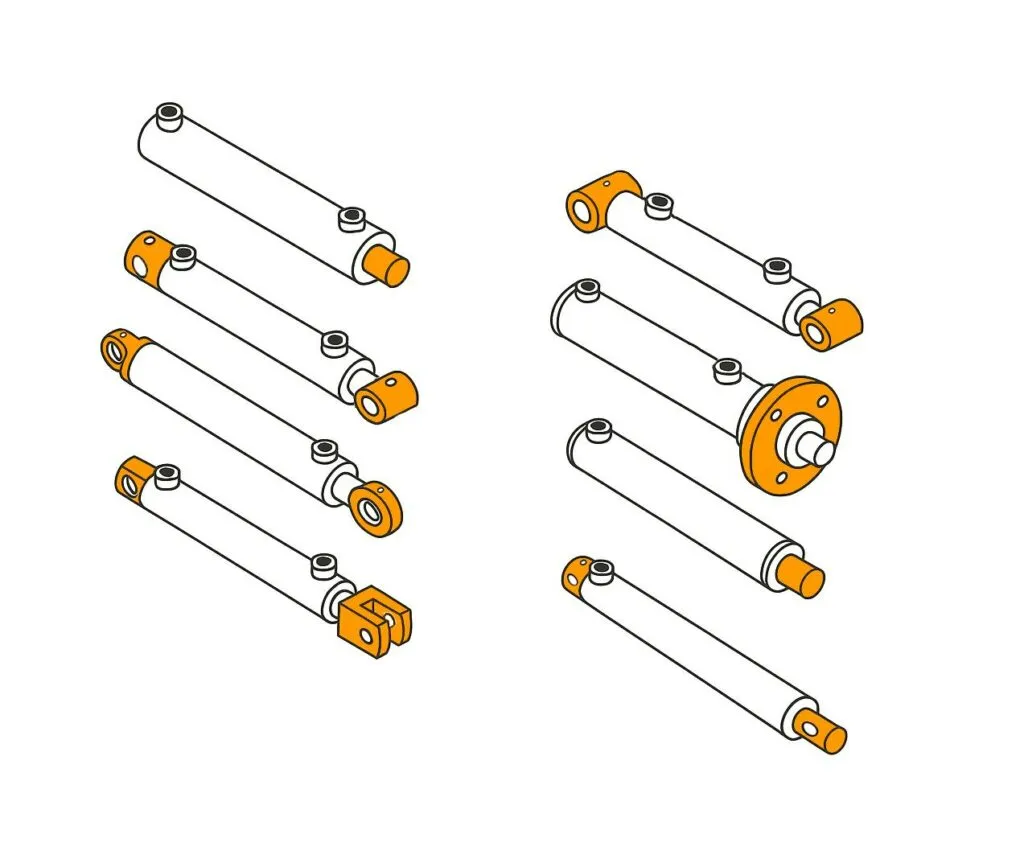
The cylinder head is located at the end where the piston rod extends and typically houses the guide and rod seal assemblies; the end cap or cylinder bottom at the opposite end seals the cylinder barrel. Different designs may secure these components using tie rods, threads, bolts, or welding. If ease of future maintenance is a priority, you should verify how the seal assemblies are removed and replaced, rather than assuming that all hydraulic cylinders can be disassembled and reassembled in the same way.
⑤ Seals and Wipers
Seals serve different functions: piston seals prevent fluid cross-flow between chambers, piston rod seals control outward fluid leakage, and static seals are used at joints without relative motion. Dust seals scrape away dirt and moisture when the piston rod retracts, but they cannot replace the piston rod seal in performing the primary sealing function. When purchasing a repair kit, you should provide the complete model number and verify the hydraulic fluid, operating temperature, and seal materials; do not simply replace parts based on matching diameters alone.
⑥ Guide Bushings and Wear Rings
Guide bushings and wear rings are used to support and guide the piston rod or piston, and to reduce direct metal-to-metal contact. They can withstand lateral forces within their design limits but cannot compensate for severe installation misalignment. For example, if disassembly and inspection reveal obvious one-sided wear, you should also check the alignment and the equipment guide rails, rather than simply replacing the seals.
⑦ Hydraulic Ports and Optional Cushions
Hydraulic ports connect to hydraulic lines, allowing fluid to enter and exit; common double-acting cylinders achieve directional control through oil passages leading to both chambers. You must verify the port threads, seal types, and locations; do not force connections between fittings that merely look similar. Some cylinders are also equipped with end-of-stroke cushions, which slow the piston as it approaches the end of its stroke by restricting oil flow. For fast-moving or heavy-duty mechanisms, assess whether cushioning is necessary, but do not assume that all cylinders come standard with this feature.
The Operating Cycle: Extension, Retraction, and Load Holding
The extension and retraction of a hydraulic cylinder rely on switching the oil flow path, while load holding requires the proper combination of valves and seals—it cannot be achieved simply by stopping the oil supply. Below, we’ll use a common single-rod, double-acting hydraulic cylinder as an example. The two sides of its piston are the rodless chamber and the rod chamber—that is, the side where the piston rod does not occupy space, and the side where the piston rod is present.
Extension: Oil Enters the Cap End
During extension, the directional control valve—which switches the flow direction of the hydraulic fluid—connects the supply line to the rodless chamber while allowing the fluid in the rod chamber to drain through the return line. When the net thrust generated by the oil pressure is sufficient to overcome the load and friction, the piston rod extends outward. For example, in certain lifting mechanisms, this action raises the platform.
You need to consider both the oil inlet and outlet simultaneously. Even if the rodless chamber is supplied with oil, the cylinder may move slowly or fail to extend properly if the return line for the rod chamber is blocked. Therefore, when encountering a situation where “there is pressure but no movement,” you cannot immediately conclude that the cylinder lacks sufficient thrust.
Retraction: The Oil Paths Reverse
During retraction, the directional control valve switches the oil supply to the rod chamber, while the oil in the non-rod chamber is drained, causing the piston rod to move back into the cylinder. Since the piston rod occupies part of the pressurized area, the retraction force is less than the extension thrust when the supply pressure is the same and return pressure and friction are neglected; with the same flow rate entering the cylinder, the retraction speed is typically faster.
This process does not apply to all cylinders. Single-acting hydraulic cylinders are typically hydraulically driven in only one direction, while the return in the opposite direction relies on gravity, springs, or external mechanisms. For example, a gravity-return lifting cylinder requires a controlled return path to lower; it does not automatically retract simply because the pump has stopped.
Load Holding: Stopping Flow Is Not Enough
Load holding refers to maintaining the desired position of a hydraulic cylinder while it is subjected to an external force. Whether the cylinder remains stationary after the directional control valve returns to the neutral position depends on the hydraulic connections at that position and system leakage. Standard spool-type directional control valves do not inherently possess the ability to reliably lock a load; even in the absence of external leakage, internal valve leakage may cause the position to drift slowly.
When load holding is required, the system can incorporate a hydraulically controlled check valve—that is, a check valve that opens a reverse flow path by controlling oil pressure. However, this is primarily used for load holding and is not suitable for controlling smooth lowering on its own. Sun Hydraulics’ technical documentation clearly distinguishes between these two functions; therefore, “being able to lock” does not equate to “being able to lower smoothly.”
Controlled Lowering: Prevent the Load from Driving the Motion
When gravity causes the mechanism to descend, the load may cause the cylinder to move faster than the speed permitted by the oil supply. In this case, a suitable load control circuit is required; a common solution is a balancing valve, which creates resistance by controlling the return flow on the load side, helping to keep the descent process under control. Whether such a valve is needed should be determined based on the direction and variability of the load; one cannot simply apply the same configuration to all cylinders.
When explaining your requirements to a supplier, you should specify three conditions: how long the load needs to be held, the maximum allowable positional change, and whether the load will actively drive the mechanism’s movement during lowering. You should also request confirmation of how the system will behave in the event of a power failure or a failure in the relevant hydraulic lines. If personnel need to enter the space beneath the lifting component for maintenance, mechanical supports or locking devices must be used in accordance with equipment requirements; hydraulic load holding must not be used as a maintenance support.
Single-Acting and Double-Acting Hydraulic Cylinders
The key difference between single-acting and double-acting hydraulic cylinders is whether hydraulic pressure drives movement in one direction or in both directions. Single-acting hydraulic cylinders are hydraulically driven in one direction, while movement in the opposite direction relies on springs, gravity, or other external forces; double-acting hydraulic cylinders, on the other hand, achieve hydraulically driven extension and retraction by alternately supplying oil to both sides of the piston. Here, “single” and “double” refer to the mode of operation, not the number of piston rods.
Single-Acting Cylinders: Hydraulic Power in One Direction
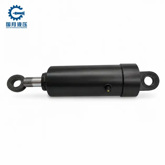
Single-acting hydraulic cylinders are suitable for mechanisms that require active force in only one direction and have reliable return conditions in the other direction. For example, a lifting mechanism can use hydraulics to lift a load and then rely on the load’s own weight to push the piston rod back. During the return stroke, the oil inside the cylinder must have a path to flow back to the reservoir; stopping the oil supply does not mean the cylinder will automatically retract.
When selecting a cylinder, you must determine the source of the return force. In designs that rely on gravity for return, the original return mechanism may fail if the cylinder is installed horizontally. When using a spring for return, you must also verify that the spring can overcome both the mechanical resistance of the mechanism and the return line backpressure—that is, the pressure resistance generated by the return line as fluid is discharged. Springs are primarily used for return; do not assume they can perform the load-bearing retraction required by the equipment.
Double-Acting Cylinders: Hydraulic Power in Both Directions
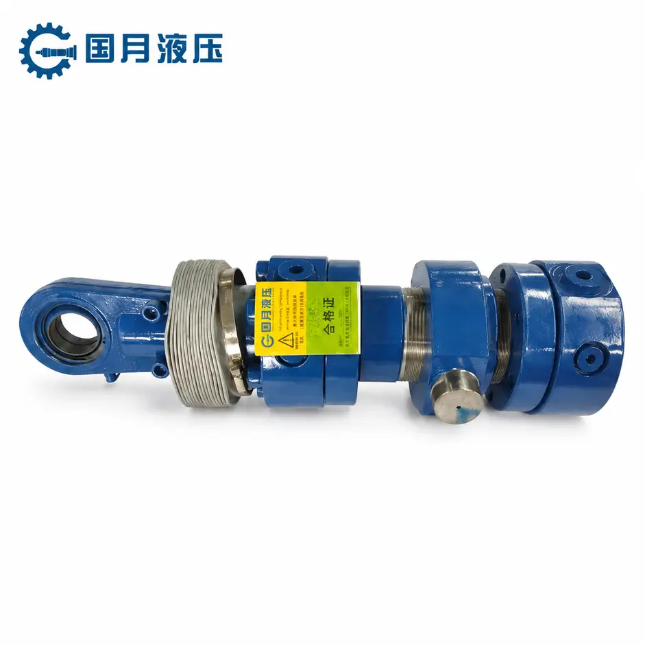
Double-acting hydraulic cylinders are suitable for mechanisms that require active force in both the extension and retraction directions. For example, in a horizontal material-feeding device that must not only push material out but also overcome resistance to retract the mechanism, a double-acting design is typically more appropriate. When the control valve switches the oil supply direction, oil enters on one side and is discharged on the other; therefore, matching oil circuits are required for both directions.
However, double-acting does not mean that the force and speed are the same in both directions. For a common single-rod configuration, the piston rod occupies part of the pressure-receiving area on the retraction side. Under conditions of equal supply pressure—and ignoring return pressure and friction—the retraction force is less than the extension force; when the inflow rate is the same, the retraction speed is faster. Therefore, you should verify the thrust and pulling force separately; you cannot rely solely on a single rated output value.
Single-Acting vs. Double-Acting: A Practical Comparison
| Comparison Item | Single-Acting Hydraulic Cylinder | Double-Acting Hydraulic Cylinder |
|---|---|---|
| Hydraulic Drive Direction | One direction | Both extension and retraction directions |
| Source of Reverse Motion | Spring, gravity, or other external forces | Hydraulic pressure |
| Common Port Configuration | Typically one port, handling both inlet and return | Typically two ports, alternating between inlet and return |
| Best Suited for | Unidirectional force output with reliable return | Bidirectional force output requiring active control of reciprocating motion |
| Key Considerations | Mounting orientation, return force, return flow resistance | Force output in both directions, flow rate, and control circuit |
| Capabilities Not Assumed by Default | Reliable retraction in any orientation | Automatic load locking or precise positioning |
The number of ports can help you make a preliminary identification, but it should not be the sole basis for decision-making. Some products also feature drain ports or vent ports; ultimately, refer to the manufacturer’s drawings and hydraulic circuit diagrams.
How to Choose for Your Application
Before requesting a quote, clearly define three key points: the force required during extension, whether the cylinder needs to carry a load during retraction, and the orientation in which the equipment will operate. Also specify the stroke—the distance the piston rod needs to travel—and the cycle time for the reciprocating motion. For example, for a mechanism that lifts vertically and relies on its own weight for reliable reset, a single-acting cylinder may be suitable; for a mechanism installed horizontally that must overcome resistance during both extension and retraction, a double-acting cylinder should be prioritized.
A common misconception is that “double-acting” means “able to safely hold a load.” Neither type of hydraulic cylinder can guarantee that a load will remain stationary based solely on its operating mode; the circuit must still be designed in conjunction with control valves, leakage conditions, and load-holding requirements. When making a selection, first confirm the operating and return conditions, then compare costs—this approach is typically more effective than simply pursuing a simpler structure or more features.
Common Hydraulic Cylinder Designs
Common hydraulic cylinder configurations include tie-rod, welded, heavy-duty industrial, and telescopic types, as well as double-rod and hollow designs for special mounting requirements. These terms describe different aspects: some emphasize how the cylinder body is connected, while others focus on the arrangement of the piston rods; therefore, they are not mutually exclusive classifications. For example, a welded hydraulic cylinder can also feature a double-acting design. You should make your selection based on mounting space, motion requirements, and maintenance methods.
Tie-Rod Cylinders
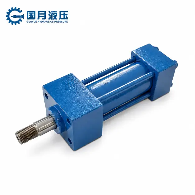
Tie-rod hydraulic cylinders use a long screw on the outside of the cylinder barrel to clamp and secure the end caps at both ends. Here, the “tie-rod” refers to the fastening component, not the piston rod that extends to push the load. This design facilitates disassembly and assembly and is commonly used in factory equipment, such as clamping mechanisms and material-feeding devices on production lines.
If ease of maintenance and standard replacement options are priorities for you, tie-rod cylinders should be your first choice. However, the external tie-rod takes up space, so you should verify the cylinder’s overall dimensions. When replacing a cylinder, do not rely solely on the bore diameter and stroke; you must also confirm that the mounting dimensions, port configurations, and piston rod end connections match.
Welded Cylinders
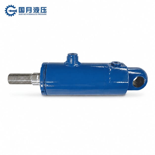
Welded hydraulic cylinders typically have components such as the cylinder base welded directly to the cylinder barrel, rather than relying on external through-rod fasteners. They feature a more compact profile, making them suitable for installation in construction machinery, agricultural machinery, and other mobile equipment. Parker’s mobile hydraulic cylinder product line includes welded single-rod cylinders and telescopic hydraulic cylinders.
“Welded” does not mean “unrepairable.” Many products still feature removable end caps, allowing the piston rod assembly to be extracted and seals to be replaced. When requesting a quote, you should confirm the specific disassembly and reassembly procedures rather than judging repair difficulty solely based on the term “welded.” Similarly, the ability to withstand high pressure and shock depends on the specific design and rated parameters—not just the structural designation.
Mill-Type Cylinders
Heavy-duty industrial hydraulic cylinders typically feature a more robust cylinder body and end connection structure, commonly found in industrial equipment such as steel and metallurgical machinery. The term Mill-Type refers to a category of industrial hydraulic cylinder structures and does not imply that they are limited to use in rolling mills. Bosch Rexroth lists these products as a separate major product category distinct from tie-rod hydraulic cylinders.
If your equipment is subject to heavy loads, repeated impacts, or prolonged continuous operation, you may want to evaluate this product category. However, “heavy-duty” does not mean the cylinder can withstand arbitrary lateral forces—that is, forces acting off the piston rod’s axis. You should still have the supplier verify the load direction, mounting supports, and operating frequency. For light-load, space-constrained mechanisms, there is no need to choose a larger, heavier design simply for the sake of “greater sturdiness.”
Telescopic Cylinders
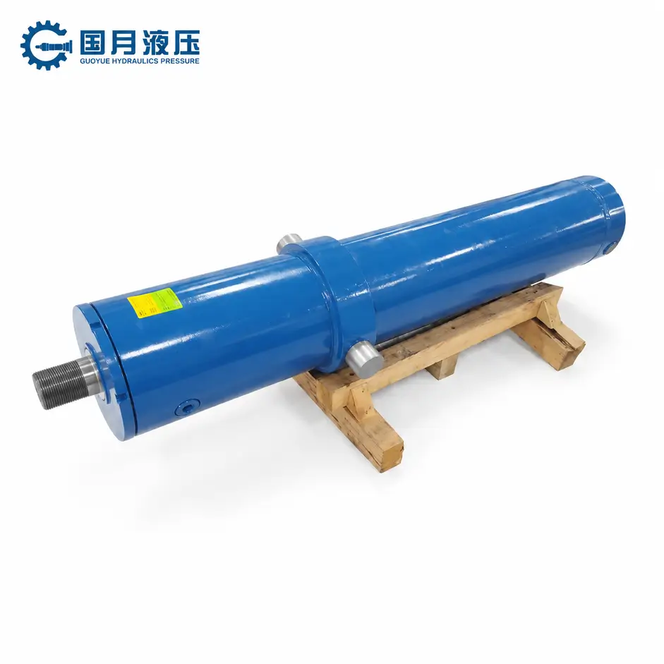
Telescopic hydraulic cylinders consist of multiple nested sleeves, enabling a long stroke—that is, a large extension distance—within a short retracted length. Lifting a dump truck bed is a typical application: installation space is limited when the bed is lowered, but a long extension distance is required during lifting.
When selecting a cylinder, you should specify both the allowable installation length when fully retracted and the required total stroke. You should also verify the force and speed of each stage, as the effective pressure area in common telescopic designs varies as different stages extend; it cannot be assumed that thrust and speed remain constant throughout the entire stroke. If the mechanism requires uniform motion or must withstand significant lateral forces, further verification is needed to ensure the design is suitable.
Double-Rod Cylinders
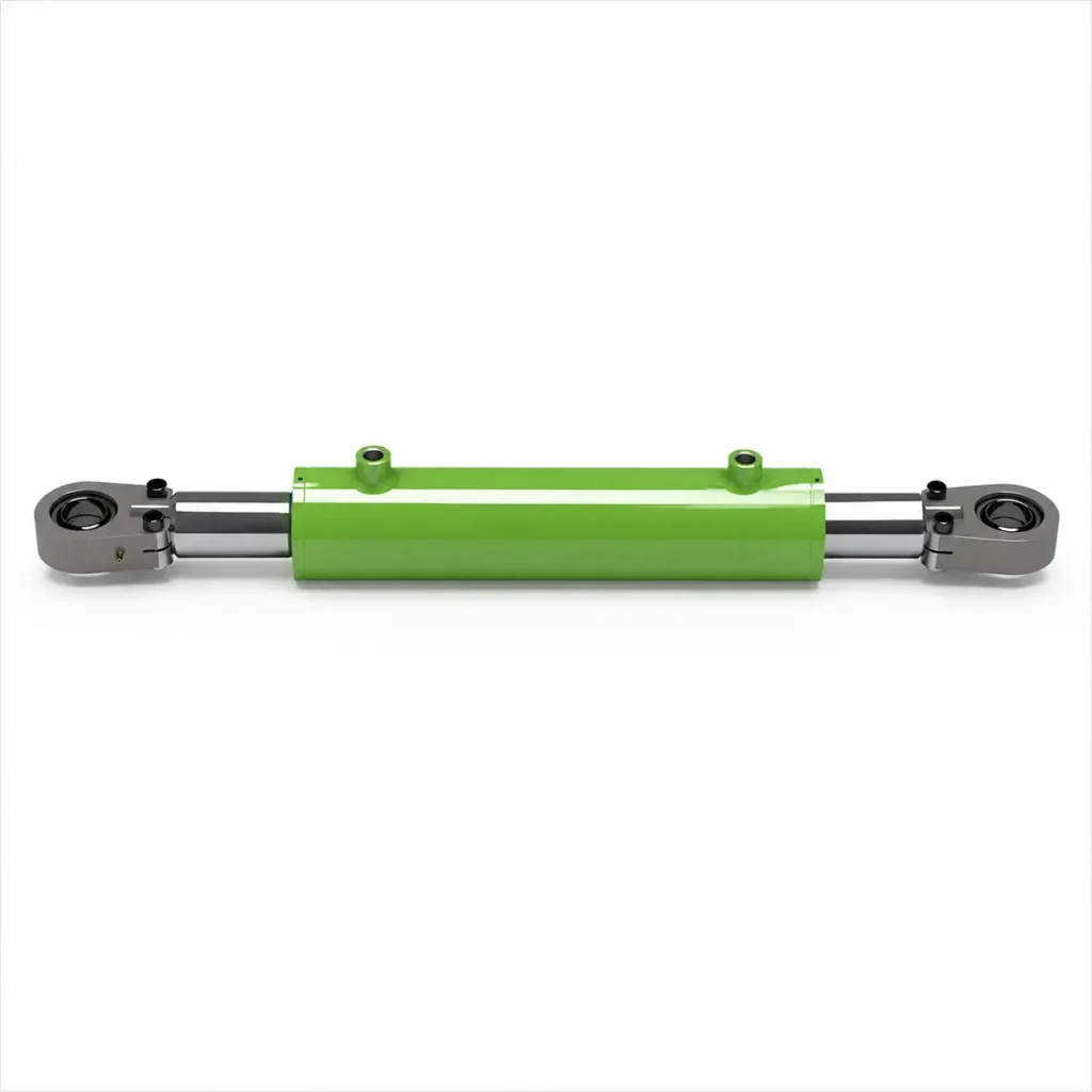
In a double-rod hydraulic cylinder, piston rods extend from both sides of the piston. For a design where the rod diameters are the same at both ends, the effective pressure-receiving areas on both sides are identical; therefore, at the same inlet flow rate, the theoretical reciprocating speeds are the same. Under the same pressure differential, the theoretical output forces in both directions are also the same.
If you require similar reciprocating motion characteristics or need to connect mechanisms to both ends of the cylinder, you may consider this design. The limitation is that space must be reserved on both sides for piston rod movement. Do not confuse “double-rod” with “double-acting”: the former describes the arrangement of the rods, while the latter describes whether hydraulic pressure drives movement in both directions.
Hollow-Plunger Cylinders
Hollow-plunger hydraulic cylinders feature a through-hole in the center that allows tie rods, cables, and similar components to pass through. They are suitable for tasks requiring the transmission of force through the center, such as tensioning, drawing, and press-fitting. For example, in a drawing machine, a tie rod passing through the center hole, in conjunction with a nut and support components, can transfer the cylinder’s force to the part being removed.
You need to verify the center bore diameter, rated force, stroke, and the load-bearing capacity of the配套 connection components simultaneously. If the application involves only general material feeding and does not require objects to pass through the center of the cylinder, there is no need to specifically choose a hollow design. The most practical approach is to first sketch out the load, mounting points, and available space, and then determine the structural type—rather than selecting the external shape first and then trying to adapt the equipment to fit the cylinder.
How Bore, Rod, Stroke, Pressure, and Flow Affect Performance
The bore diameter and pressure determine the theoretical output force of a hydraulic cylinder; flow rate and effective pressure area determine the speed of movement; stroke determines the distance traveled; and rod diameter affects the retraction force and the load-bearing stability of the piston rod. These five parameters must be considered together. For example, increasing the bore diameter can increase thrust, but the motion will slow down if the oil supply flow rate remains constant. The following explanation uses a common single-rod, double-acting hydraulic cylinder as an example.
Bore: More Force Requires More Oil
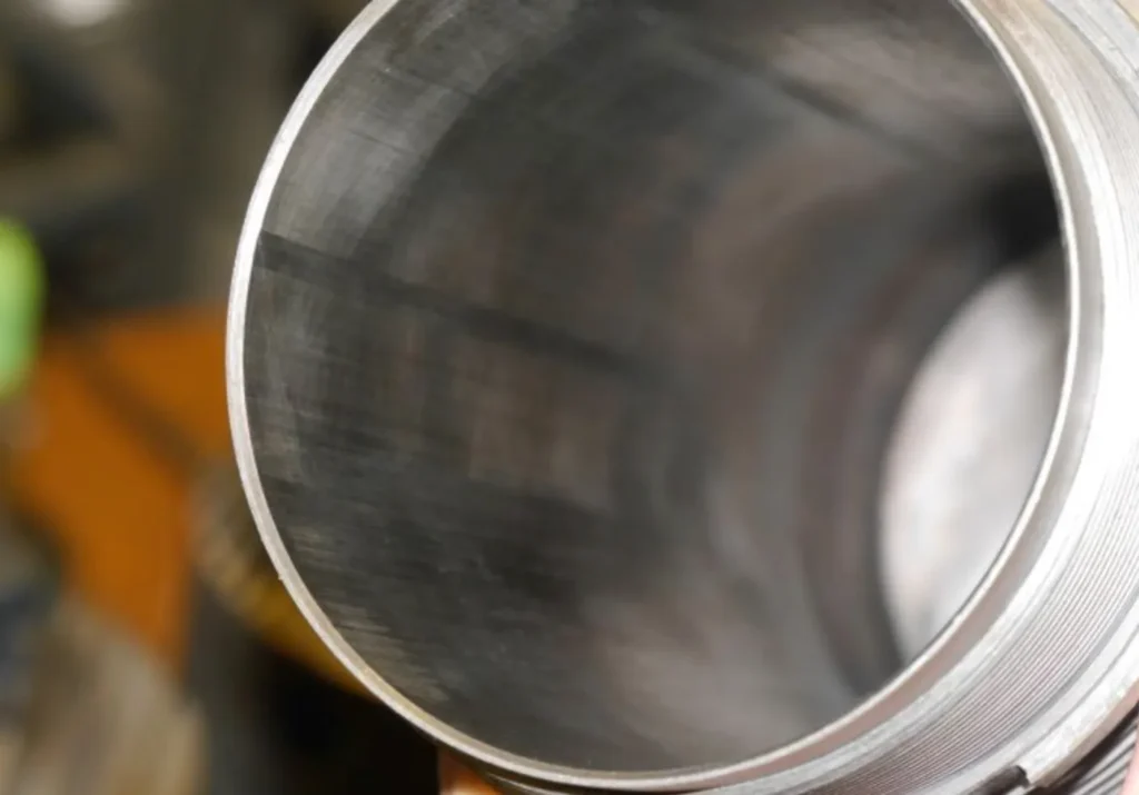
The bore is the inner diameter of the cylinder barrel and determines the piston’s effective area. Ignoring return pressure and friction, theoretical thrust = pressure × piston area. Since the area is proportional to the square of the bore, doubling the bore will quadruple both the area and the theoretical thrust at the same pressure.
However, a larger area also requires more fluid to complete the same distance of travel. If the fluid flow rate remains constant, the theoretical extension speed after doubling the bore diameter will drop to one-fourth of the original value. Therefore, when you want to increase thrust, you should simultaneously check the cycle time and the pump’s flow capacity to avoid the problem of “being able to push but not having enough time to complete the motion.”
Rod Diameter: Strength and Retraction Force
Rod diameter refers to the diameter of the piston rod. All other conditions being equal, a thicker piston rod is generally better able to resist bending under pressure, making it particularly suitable for applications requiring verification of load-bearing stability over long strokes. However, as the rod diameter increases, the surface area on the rod side available for the oil pressure to act upon decreases. Therefore, with the same cylinder bore and oil supply pressure—and ignoring return pressure and friction—increasing the piston rod diameter will reduce the theoretical retraction force.
For example, when selecting a mechanism that must both push forward and retract under load, you cannot base the selection solely on the extension thrust. You should specify the required thrust and pull forces separately so that the supplier can verify the rod diameter and the force output in both directions simultaneously. The piston rod should also not be used as a substitute for equipment guide rails to bear significant lateral loads.
Stroke: Travel Distance and Stability
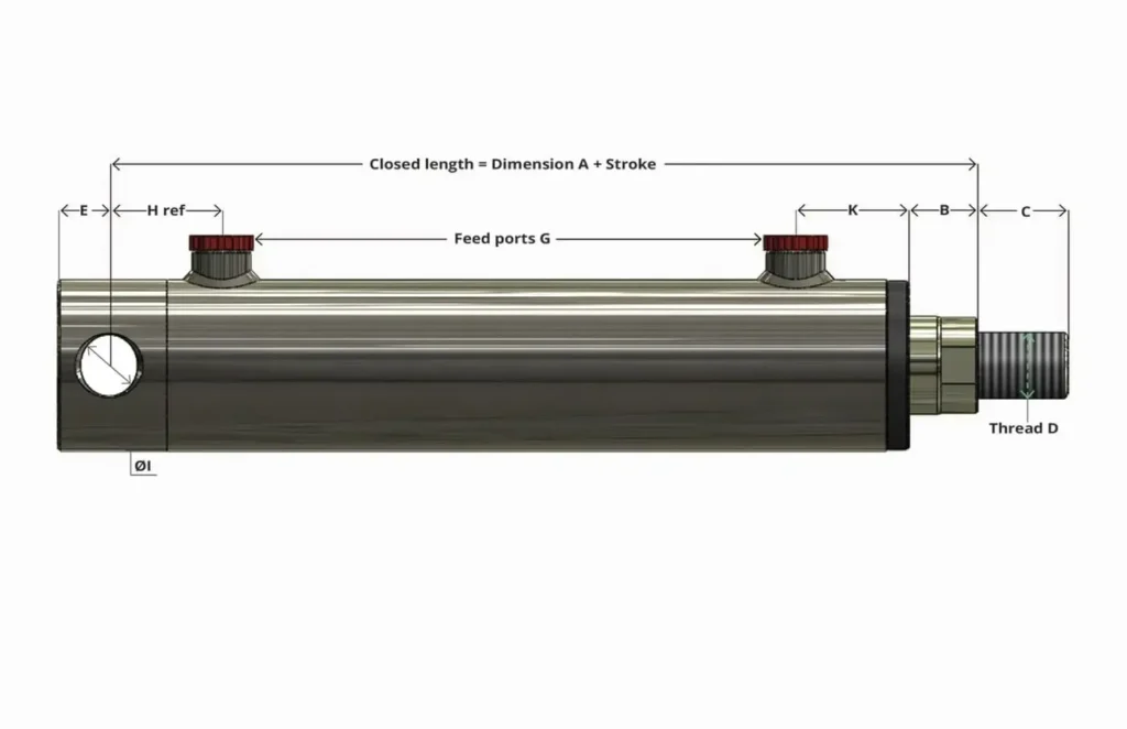
Stroke is the distance the piston rod travels from fully retracted to fully extended. Increasing the stroke does not directly increase thrust, but it does increase the amount of oil required and the time needed to complete the full cycle. At a constant speed, doubling the stroke from 250 mm to 500 mm will also double the theoretical motion time.
For long-stroke cylinders that push loads under compression, you must also check for buckling—that is, when the piston rod buckles and becomes unstable under compression, similar to a slender rod. This is related to the rod diameter, extension length, and mounting supports; safety cannot be determined solely by thrust calculations. You should provide an installation drawing and load specifications at maximum extension for the manufacturer to verify, rather than simply choosing “a bit more stroke.”
Pressure: Available Force, Not a Speed Setting
Pressure represents the force exerted by hydraulic fluid per unit area, commonly measured in MPa (megapascals) or bar, where 1 MPa = 10 bar. For the same effective area, increasing pressure can increase the theoretical output force; however, the actual operating pressure depends on the load and system control and does not always equal the rated pressure specified on the product.
For example, if a hydraulic cylinder rated for a maximum operating pressure of 20 MPa is connected to a system that can only actually supply 10 MPa, the available force cannot be calculated based on 20 MPa. You also cannot arbitrarily increase the pressure just to make the motion faster; when the force is already sufficient, speed depends primarily on the flow rate entering the cylinder. Pressure settings must also fall within the allowable ranges of the cylinder, valves, piping, and fittings.
Flow: How Fast the Cylinder Moves
Flow rate is the volume of hydraulic fluid entering the cylinder per unit of time, typically expressed in L/min (liters per minute). Assuming no leakage, the theoretical speed = flow rate ÷ effective pressure area on that side. Therefore, doubling the flow rate to a single cylinder will double its theoretical speed, provided that the pump, valves, and piping can deliver this flow rate at the required pressure.
For a typical single-rod, double-acting cylinder, the effective area on the rod side is smaller; therefore, when the inflow rate is the same in both directions, retraction is usually faster than extension. You should verify the extension and retraction times separately and check the cylinder’s allowable speed and deceleration requirements at the end of the stroke to avoid causing end-of-stroke impact simply by increasing the flow rate.
A Worked Example: Putting the Parameters Together
Assume a cylinder bore of 50 mm, a rod diameter of 30 mm, and a stroke of 500 mm; for calculations in both directions, assume an inlet pressure of 10 MPa and an inlet flow rate of 10 L/min. In a standard directional control circuit, ignoring return pressure, friction, leakage, and acceleration/deceleration processes, the theoretical results are as follows:
| Performance Parameter | Extension | Retraction |
|---|---|---|
| Effective Pressurized Area | Approx. 1,963 mm² | Approx. 1,257 mm² |
| Theoretical Output Force | Approx. 19.6 kN | Approx. 12.6 kN |
| Theoretical Speed | Approx. 84.9 mm/s | Approx. 132.6 mm/s |
| Time to Complete a 500 mm Stroke | Approx. 5.9 seconds | Approx. 3.8 seconds |
Here, kN stands for kilonewtons; 1 kN = 1,000 N, which is a unit of force. As you can see, under the same inlet pressure and flow rate, the same hydraulic cylinder delivers greater extension force and a faster retraction speed. When selecting a cylinder, first determine the load, travel distance, and target cycle time; then verify the pressure and flow rate the system can simultaneously provide; and finally, verify the rod diameter and mounting method. Do not directly treat the theoretical output force as the equipment’s allowable working load.
Typical Hydraulic Cylinder Applications
Hydraulic cylinders are primarily used for lifting, pushing, pulling, clamping, pressing, and adjusting the position of mechanisms. You’ll find them on excavators, dump trucks, agricultural machinery, forklifts, and industrial presses. They are suitable for applications requiring significant linear force, where installation space is limited, or where the equipment already has a hydraulic system. Although the piston rod moves in a linear motion, it can also drive bucket rotation or body tilting through articulated mechanisms.
Construction and Earthmoving Equipment
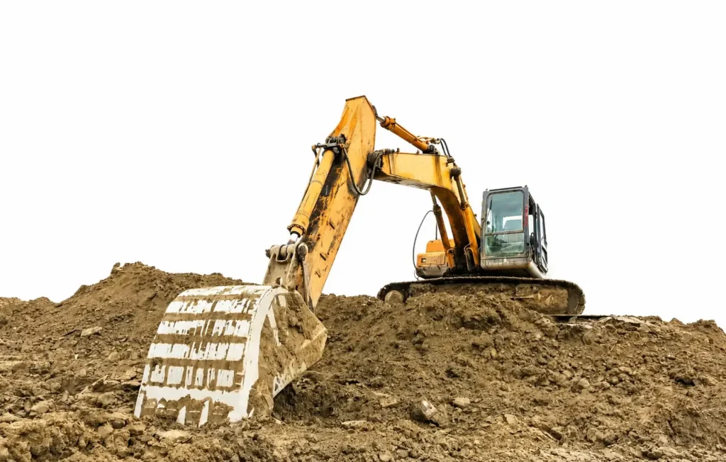
On excavators, hydraulic cylinders control the boom, stick, and bucket; on loaders, they are responsible for lifting and tipping the bucket. This type of equipment must handle constantly changing loads and is exposed to impacts, mud, sand, and outdoor environments; therefore, selection should not be based solely on maximum thrust. Construction machinery is also explicitly listed by hydraulic cylinder manufacturers as a primary application area.
For example, for materials of the same weight, the farther the distance from the pivot point, the greater the force required by the lifting mechanism may be. You should provide mechanical diagrams for different operating positions so that suppliers can verify the force requirements across the entire range of motion, while also confirming piston rod protection, seals, and mounting connections. Estimating thrust solely by “material weight ÷ number of cylinders” can easily overlook the impact of mechanical angles.
Dump Trucks and Tipping Bodies
Dump trucks use hydraulic cylinders to lift the body, allowing bulk material to slide down the inclined body. Telescopic hydraulic cylinders can provide a long stroke with a short retracted length, making them suitable for certain body-lifting configurations; other configurations may use standard single-stage hydraulic cylinders in conjunction with a link mechanism.
When selecting a cylinder, you must consider the combined weight of the body and cargo, the center of gravity, the mounting points, and the target tilt angle. The cylinder’s rated thrust should not be directly equated with the vehicle’s maximum allowable cargo weight. The initial lifting position often requires careful calculation, but the specific worst-case scenario depends on the mechanical geometry and load distribution.
Agricultural Machinery
Agricultural machinery uses hydraulic cylinders to lift implements, fold wing-type frames, adjust header height, or control loading and unloading attachments. It is suitable for applications requiring high output where the tractor or machine already provides hydraulic power. Agricultural machinery is also a well-established application area for hydraulic cylinders.
For example, folding implements must not only unfold during operation but also remain folded during transport. You should confirm whether hydraulic drive is required in both directions and verify transport locking requirements; you cannot rely solely on closing the control valve as a substitute for the specified mechanical lock. When stored outdoors, attention must also be paid to piston rod corrosion protection and dust seals—dust seals are used to prevent mud and sand from entering the cylinder along the piston rod.
Material Handling and Lifting Equipment
Forklifts, vehicle tailgates, and some lifting platforms use hydraulic cylinders to lift cargo or adjust the position of mechanisms. For example, a forklift’s lift cylinder may drive the forks via a chain, while a tilt cylinder is used to change the angle of the mast. Since this type of equipment performs repetitive motions, in addition to force output, you should also consider operating frequency, smoothness of operation, and ease of maintenance.
You should provide the supplier with the target lift height, lifting time, and load-holding requirements. The cylinder stroke does not necessarily equal the actual travel distance of the forks or platform, as chains, pulleys, or scissor mechanisms can alter the motion relationship. When handling loads at heights, you should also verify the machine’s controlled descent and fail-safe protection designs; suitability cannot be determined solely by the cylinder’s ability to lift the load.
Industrial Pressing and Clamping
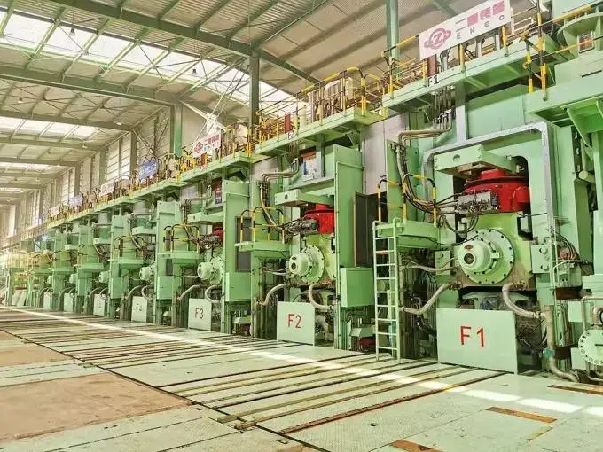
In industrial equipment, hydraulic cylinders can drive a ram to perform press-fitting and forming operations, or they can secure workpieces using clamping fixtures. For example, pressing a bushing into a housing requires sufficient pressing force; clamping thin-walled parts, however, requires limiting the clamping force to prevent workpiece deformation. Therefore, greater force is not necessarily better; the key is whether the force and motion process meet the process requirements.
If your press-fitting process requires determining whether a part is properly seated, you must clearly define the forces and displacements to be monitored—that is, the press-fitting force and the travel distance. A hydraulic cylinder alone cannot automatically perform precise detection; appropriate sensors and a control system are also required. For light-load, simple reciprocating motions, you may also consider pneumatic or electric alternatives to avoid adding an entire hydraulic system for a minor operation.
Waste Compaction and Recycling
Waste compaction trucks and equipment use hydraulic cylinders to drive a compaction plate, compressing the material and ejecting it. Parker’s mobile hydraulic cylinder documentation also lists the compaction and ejection mechanisms in waste vehicles as typical applications.
The resistance encountered by this type of equipment varies depending on the material, so cylinders should not be selected based solely on no-load operation. You should specify any hard objects that may be encountered, potential jamming conditions, and the number of cycles per hour so that the supplier can verify the force output, durability, and overload protection. Off-center loads on the compaction plate should also be supported by a proper guide structure; the piston rod should not be used as the compaction plate’s guide rail.
How to Select the Right Hydraulic Cylinder
When selecting a hydraulic cylinder, you should first determine the load, travel distance, and cycle time, and then confirm the pressure, flow rate, mounting configuration, and operating environment. Two cylinders with the same bore diameter and stroke may have completely different applications due to differences in rod diameter, seals, or mounting configurations. Parker’s selection guidelines also emphasize that load capacity, stroke, speed, temperature, and mounting configuration must be considered together.
Define the Load and Motion
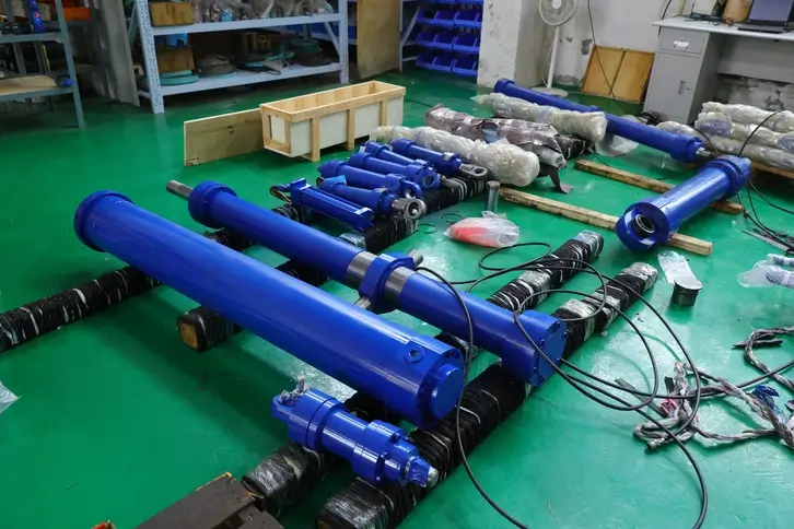
First, specify the action the cylinder is intended to perform: lifting, pushing, retracting, or clamping. You need to provide the maximum load, the direction of the force, and whether there is impact or frequent start-stop operation. For example, when pushing a slide horizontally, you must overcome friction and acceleration resistance; therefore, the weight of the slide cannot be directly equated to the required thrust. When lifting via a link, you must also calculate the effect of the mounting angle on the output force.
If hydraulic force is required in only one direction and springs or gravity can reliably return the load to its original position, a single-acting cylinder may be considered. If loaded motion is required in both directions, a double-acting cylinder should be evaluated first. Design margins should be determined based on shock loads, load variations, and application requirements; it is not advisable to apply a single percentage to all equipment.
Match Force and Speed to the Hydraulic Supply
Next, confirm how much pressure and flow the system can actually deliver to the cylinder during operation. Pressure and the effective piston area determine the force output, while flow affects speed; therefore, both must be verified simultaneously. Do not assume that the pump’s maximum pressure and maximum flow rate will necessarily be achieved simultaneously under operating conditions.
For example, suppose a cylinder needs to extend 300 mm and complete the extension within 3 seconds; the average speed would be 100 mm/s. You can provide this requirement to the supplier, who will calculate the required flow rate based on the cylinder bore diameter, taking into account startup, deceleration, and valve circuit losses. This is merely an example of calculating motion requirements and does not imply that the cylinder should operate at a constant speed throughout the entire stroke.
Check Stroke, Space, and Mounting
Stroke is the distance the piston rod must travel, but it is not equal to the total length of the cylinder when retracted. You should verify the mounting dimensions in both the retracted and extended states and allow for space for fittings, hoses, and maintenance. For example, a cylinder may have sufficient stroke but be too long when retracted to fit into the equipment. Both installation space and stroke are basic check items in the manufacturer’s selection guide.
The mounting method must also accommodate the motion of the mechanism. If the cylinder needs to swing with a connecting rod, use a connection that allows for the corresponding rotation. For long-stroke compression applications, verify the piston rod’s buckling resistance—that is, its ability to resist buckling instability under compression. Do not rely on increasing the bore diameter to compensate for misalignment, and do not assume that the piston rod can serve as a guide rail for the equipment.
Match Seals and Materials to the Environment
You need to inform the supplier of the specific type of hydraulic fluid, operating fluid temperature, ambient temperature, and whether the system will be exposed to mud, salt spray, or cleaning fluids. Seal materials must be compatible with the fluid and temperature; the piston rod’s material and surface treatment must be suitable for external corrosion and wear conditions.
For example, indoor fixtures and coastal outdoor equipment may require different corrosion protection solutions even if they exert the same thrust. Do not simply specify “high-temperature resistant” or “rust-proof”; instead, provide the actual temperature range, contact media, and exposure conditions so that the supplier can make an informed material selection.
Specify Duty Cycle and Control Requirements
The duty cycle is the process of a single complete operation of the equipment, including extension, dwell, retraction, and standby. You should specify the number of cycles per hour, daily operating time, and how long the load needs to be held. Maintenance equipment that operates intermittently and production equipment that operates continuously in a back-and-forth motion may have different requirements for seals, guides, and durability.
If you require the cylinder to stop at a specified position, clearly define the allowable positional error; if load holding is required, specify the allowable movement, the duration of hold, and the behavior in the event of a failure. Position sensors measure position, and load-holding valves restrict fluid flow, but the final result still depends on the entire control loop. Do not assume that a cylinder meets positioning and holding requirements simply because it is “sensor-equipped” or “double-acting.”
Confirm the Design Before Ordering
When requesting a quote, the most useful information is an installation diagram accompanied by a complete description of the operating conditions. The diagram should indicate connection points and the range of motion, while the description should clearly specify thrust, tensile force, stroke, cycle time, pressure, flow rate, hydraulic fluid, temperature, and operating frequency. Ask the supplier to clearly state which requirements can be met and which require modification or verification.
Before placing an order, reconfirm the drawing version, port specifications, seal maintenance kits, and acceptance criteria. New designs should be validated through prototype testing to verify installation, operation, and performance under load; when replacing an old cylinder, verify the original model and key interfaces. Just because the external dimensions are similar and the cylinder fits does not mean that performance and system compatibility are assured.
Common Failure Modes and Maintenance Basics
Common problems with hydraulic cylinders include external oil leaks, load drift, slow or jerky movement, and damage to the piston rod and seals. These issues are not necessarily caused by the cylinder itself; control valves, insufficient oil supply, and installation errors can also produce similar symptoms. You should first document the conditions under which the fault occurs before determining the cause, to avoid replacing seals or increasing pressure as soon as an abnormality is detected.
External Leakage: Check the Source First
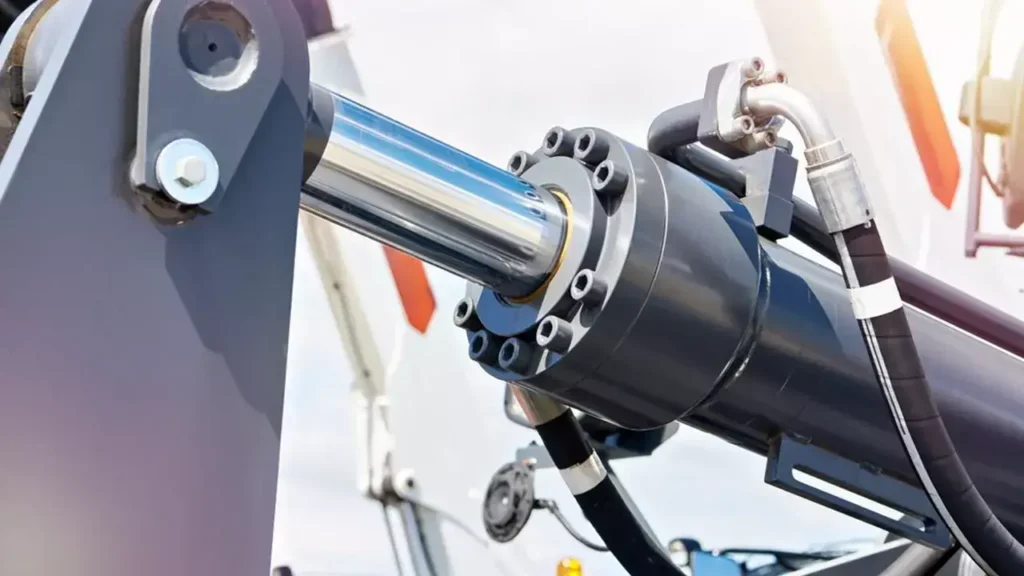
External leakage occurs when hydraulic fluid flows out through the piston rod outlet, cylinder body connections, or port fittings. Leaks at the piston rod may be related to seal wear, scratches on the rod surface, or misalignment during installation; leaks at fittings require inspection to ensure proper connections and seals. Parker’s maintenance documentation also lists seal damage and piston rod surface issues as key inspection points.
Upon discovering oil stains, you should shut down the equipment, ensure it is safely isolated, and clean the surface before having qualified personnel inspect the leak location in accordance with established procedures. A thin film of lubricating oil on the piston rod does not necessarily indicate a malfunction, but persistent oil buildup, dripping, or a noticeable increase in leakage requires attention. For example, if the rod surface is already scratched, simply replacing the seal without repairing the damage may result in the leak recurring quickly.
Load Drift: Check the Cylinder and the Valves
Load drift refers to the slow movement of the piston rod or load without a motion command being issued. Possible causes include internal leakage—where fluid flows past seals or through valve orifices within components—as well as issues with control valves or load-holding valves. The absence of visible external oil leaks does not mean the entire circuit is properly sealed; similarly, load sagging does not directly prove that the piston seals are damaged. Parker’s troubleshooting documentation explicitly requires that other components in the circuit be considered simultaneously.
You can record the load size, oil temperature, piston rod position, and the amount of movement over a specific period of time, and provide this information to maintenance personnel for evaluation. For example, if operation is normal when the machine is cold but drift accelerates after it warms up, this is a useful troubleshooting clue. To determine whether the condition is abnormal, compare it with the equipment’s allowable limits; when distinguishing between cylinder and valve leaks, have a professional perform the required tests—do not attempt to loosen the lines connected to the load-bearing cylinder yourself.
Slow or Jerky Movement: Look Beyond the Cylinder
Slow movement may result from insufficient oil flow, valve restrictions, internal leakage, or increased mechanical resistance. Intermittent stopping and starting at low speeds—known as “crawling”—may be related to seal friction, misalignment, or air ingress. Therefore, the same type of motion abnormality may correspond to multiple causes.
For example, if jerking occurs during the first operation after maintenance, check whether the system was bled according to the manufacturer’s procedures; if the movement slows noticeably only under load, further verification of actual pressure, flow rate, and mechanical resistance is required. Do not bleed the system by repeatedly slamming the cylinder against the end of its stroke, and do not treat increasing the pressure as a universal solution. Refer to the specific product instructions for bleeding locations, operating procedures, and allowable pressures.
Rod and Guide Damage: Correct the Alignment
Scratches, rust, or bending of the piston rod can damage seals and may cause oil leaks or sticking. Guides are support components that help the piston and piston rod maintain their direction of movement; misalignment during installation, loose connections, or excessive lateral forces can all increase wear on these components.
For example, if a feed plate lacks effective guide rails, the resistance caused by material shifting to one side may be directly transmitted to the piston rod. In such cases, simply replacing the cylinder with an identical one will not eliminate the root cause. You should inspect the guide rails, pins, connection clearances, and installation alignment; piston rods that are visibly bent or severely scratched should be evaluated by a maintenance team for repair or replacement—they should not be arbitrarily ground down or straightened on-site.
Contamination and Heat: Protect the Sealing System
Particulate contamination can scratch moving surfaces, wear down seals, or interfere with the operation of control valves. Excessive heat can accelerate seal aging and alter the viscosity of the hydraulic fluid—that is, how thick it feels when flowing. Damaged dust seals, open hydraulic ports during maintenance, and the use of incompatible hydraulic fluid all increase the risk of failure.
Routine maintenance should include keeping the piston rod and surrounding areas clean, inspecting dust seals, and maintaining filters and hydraulic fluid according to the machine’s specifications. You should not judge the condition of the fluid solely by whether it “looks clean,” nor should you set the same oil change interval for all equipment. When seal failures occur repeatedly, you should investigate oil temperature, contamination levels, and material compatibility rather than simply shortening the seal replacement interval.
Establish a Simple Maintenance Routine
You can create an inspection log to continuously record leak locations, the condition of the piston rod surface, loose connections, cycle times, and operating oil temperature. Comparing these records under similar load and temperature conditions makes it easier to detect changes than occasional visual inspections. Inspection frequency should follow the equipment manual and be adjusted based on usage frequency and environmental conditions; after repairs, verify that leaks, operation, and load holding meet specified requirements.
Before disassembly, the load must be securely supported, the power source isolated, and residual pressure released and verified in accordance with the equipment procedures. Stopping the pump does not mean the cylinder has been depressurized, nor does a zero reading on the pump-side pressure gauge prove that all sealed oil chambers are pressure-free. Do not use your hands to locate high-pressure leaks, and do not relieve pressure by arbitrarily loosening fittings; use the specified mechanical supports when performing maintenance while the cylinder is in a raised position.
Hydraulic Cylinders vs. Pneumatic and Electric Actuators
Hydraulic cylinders are suitable for linear motion requiring high output force, while pneumatic cylinders are commonly used for simple, rapid reciprocating motions. Electric actuators, on the other hand, facilitate programmable position and speed control. An actuator is a device that converts input energy into mechanical motion. The electric actuators compared here primarily refer to products in which a motor generates linear motion through mechanisms such as lead screws or synchronous belts.
| Comparison Criteria | Hydraulic Cylinder | Pneumatic Cylinder | Electric Actuator |
|---|---|---|---|
| Power Source | Pressurized fluid, typically hydraulic oil | Compressed air | Electric motor and mechanical transmission mechanism |
| Common Applications | Heavy-duty lifting, pressing, construction machinery | Material feeding, sorting, simple clamping | Multi-position positioning, programmable pushing, assembly |
| Control Features | Can control force, speed, and position when paired with appropriate valves and feedback systems | Standard circuits are suitable for reciprocating motion; compressed air can affect motion rigidity | Easy to adjust motion programs when paired with a driver and position feedback |
| Maintenance Focus | Hydraulic fluid, seals, leaks, and filtration | Air supply quality, air leaks, and seals | Lubrication, transmission wear, and electrical connections |
| Considerations for Selection | Consider pumps, valves, reservoirs, and piping together | Verify output force and air consumption at actual operating pressures | Verify thrust, speed, operating frequency, and temperature rise |
These are common selection tendencies, not absolute boundaries. For example, there are high-thrust electric actuators, and hydraulic systems can also achieve precise positioning. You should evaluate whether the complete system meets the requirements, rather than simply assuming that “hydraulics are only suitable for high forces, while electric systems are only suitable for low forces.”
Frequently Asked Questions About Hydraulic Cylinders
Q1: What Is the Difference Between a Hydraulic Ram and a Hydraulic Cylinder?
A hydraulic ram cannot be translated as “hydraulic jack” across the board. In some engineering contexts, it refers to a piston-type hydraulic cylinder that is typically extended by hydraulic pressure and retracted by an external force; in some product documentation, “ram” is also used broadly as an alternative term for a hydraulic cylinder. “Hydraulic cylinder,” on the other hand, is a more general term that encompasses a variety of structures and operating mechanisms.
A hydraulic jack—commonly referred to as a “hydraulic jack”—is a tool primarily designed for lifting, and may integrate a cylinder, pump, and reservoir into a single unit. When purchasing, you should verify the structure, retraction method, and power configuration; you cannot determine whether they are interchangeable based solely on the terms “ram,” “cylinder,” or “jack.”
Q2: What Fluid Is Used Inside a Hydraulic Cylinder?
Most hydraulic cylinders use hydraulic fluid compatible with the system; mineral oil-based hydraulic fluid is the most common. Certain applications may use fire-resistant hydraulic fluids such as water-glycol blends or biodegradable hydraulic fluids, provided that the pumps, valves, seals, and materials are compatible.
You should consult the equipment manual to confirm the fluid type and viscosity grade; viscosity refers to the fluid’s resistance to flow. Do not substitute engine oil, brake fluid, or water, and do not mix fluids simply because their colors are similar; fluid compatibility cannot be determined by appearance alone.
Q3: How Much Force Can a Hydraulic Cylinder Produce?
There is no standardized force rating for hydraulic cylinders; the theoretical force depends on pressure and the effective pressure-bearing area. Taking extension as an example, and ignoring return pressure and friction, thrust = pressure × piston area. Assuming a cylinder bore of 50 mm and a pressure of 10 MPa, the theoretical extension force is approximately 19.6 kN, where kN stands for kilonewtons, and 1 kN = 1,000 N.
This value is a calculation example and does not represent the actual load-bearing capacity. Actual selection must also consider return pressure, friction, mounting angle, piston rod stability, and structural rating; single-rod hydraulic cylinders have a smaller retracting area, so the extension force cannot be directly used as the tensile force.
Q4: Can a Hydraulic Cylinder Work in Either Direction?
Double-acting hydraulic cylinders can be driven by hydraulic pressure to extend and retract; single-acting hydraulic cylinders are hydraulically driven in only one direction, while the opposite direction relies on springs, gravity, or other external forces. Therefore, single-acting cylinders can also perform reciprocating motion, but it cannot be assumed that they can actively carry loads in both directions.
For example, when a horizontal mechanism needs to push material and then pull it back against resistance, a double-acting solution should generally be considered. You also need to verify the output force and speed in both directions separately, as the reciprocating performance of a standard single-rod double-acting cylinder differs between directions.
Q5: Why Do Hydraulic Cylinders Leak?
Leaks can result from seal wear, piston rod scratches, contamination, misalignment during installation, improper temperature, or damage to connections. External leaks allow fluid to flow outside the equipment; internal leaks occur within the component and may affect output force or load holding, but fluid may not necessarily be visible from the outside.
You should first identify the leak location and cause before deciding on a repair method. For example, if the piston rod surface is already damaged, simply replacing the seal may result in another leak soon after. Load sagging may also be related to the control valve; it cannot be directly attributed to internal cylinder leakage, and you should never use your hands to locate high-pressure leak points.
Q6: How Long Does a Hydraulic Cylinder Typically Last?
There is no fixed service life for hydraulic cylinders that applies to all operating conditions. Load, cycle count, pressure surges, fluid cleanliness, corrosion, and installation conditions all affect service life. Seals, guide components, and metal structures also have different service lives; replacing a seal does not necessarily mean the entire cylinder is at the end of its service life.
If a supplier claims a product will last a certain number of years or complete a certain number of cycles, you should ask for details regarding the corresponding load, pressure, stroke, temperature, and failure criteria. The durability of equipment that operates a few times a day cannot be compared solely based on calendar years to that of a production line running continuously.
Q7: Can a Damaged Hydraulic Cylinder Be Repaired?
Many hydraulic cylinders can be repaired, such as by replacing seals and guide components, or by having a professional repair shop address damage to the piston rod or cylinder barrel. However, whether repair is worthwhile depends on the extent of the damage, the availability of replacement parts, and whether the cylinder can regain its specified performance after repair. The manufacturer’s repair policy may also restrict the replacement or repair of certain pressure-bearing components.
You should request that the repair provider provide a damage inspection report, a scope of repair, and an acceptance plan. For components that are severely bent, cracked, or deformed, the determination that they are safe for continued use cannot be based solely on the fact that “there are no oil leaks after repair”; verification of functionality, sealing, and operating pressure after repair is equally important.
Q8: Why Is Air in a Hydraulic Cylinder a Problem?
Air is more compressible than hydraulic fluid. When unbleed air is present in a cylinder, part of the incoming fluid first compresses the air before moving the load, which can cause slow response, soft motion, judder, or unstable positioning. Air also stores compressed energy, making motion and pressure relief behavior more unpredictable.
For example, if erratic motion occurs after replacing a hose or performing repairs, check whether bleeding was performed according to the manufacturer’s specifications. You must use the bleed points and procedures specified for that model; do not arbitrarily loosen fittings while the cylinder is under pressure or bearing a load. Installation orientations and bleeding methods vary by cylinder model.
Choosing a Trusted Hydraulic Cylinder Manufacturer
From standard hydraulic cylinders to custom solutions, we help you improve equipment performance, delivery reliability, and batch consistency
Explore Rivmate Cases

Hey There, I'm Melody!
We are a hydraulic cylinder manufacturer. For over 20 years, we have focused on producing reliable hydraulic cylinders. Need a hydraulic cylinder solution? Feel free to contact us.