Home / Hydraulic vs. Pneumatic Cylinders: Key Differences
Hydraulic vs. Pneumatic Cylinders: Key Differences
- Author: GY Hydraulic
- 20+ Years of Manufacturing
Hydraulic cylinders use pressurized fluid to drive the piston, while pneumatic cylinders use compressed air to drive the piston. Both can perform linear pushing and pulling motions, but their typical operating pressures differ, and air is more compressible than hydraulic fluid. If the installation space is very narrow and a large axial force is required, a hydraulic cylinder should be evaluated first; if the application involves short-stroke, repetitive material-pushing or material-stopping motions and there is an ample on-site air supply, a pneumatic cylinder is often worth considering first.
The key to understanding the difference between hydraulic and pneumatic cylinders is to compare the two types in the context of the same specific task. First, clarify: what is the actual pressure available at the cylinder ports; how much force is required for extension and retraction; how the equipment will be stopped; and whether the load will move after the air supply or pump is shut off. Comparing only the price, no-load speed, or maximum pressure listed on the nameplate can easily lead to contradictory conclusions.
Table of Contents
Hydraulic vs. Pneumatic Cylinders at a Glance
Use the table below for an initial screening. The guidelines in the table apply to common industrial configurations; they must ultimately be verified against specific model numbers, supply conditions, and operating conditions.
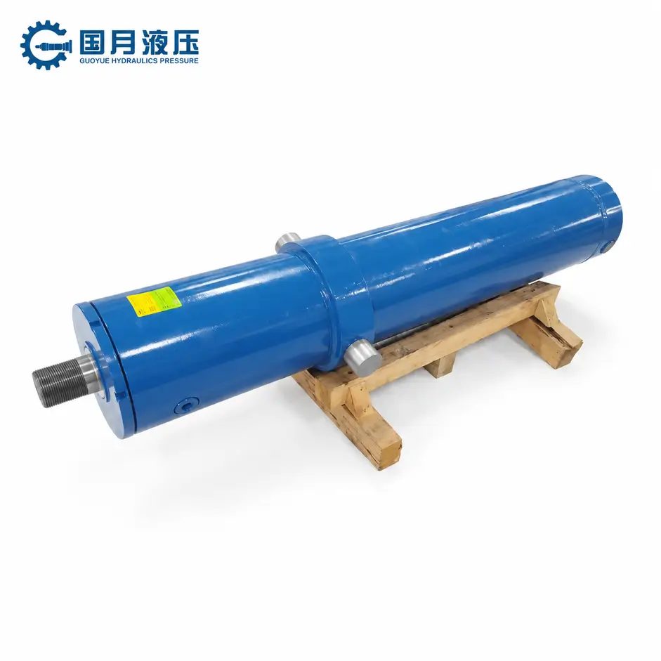
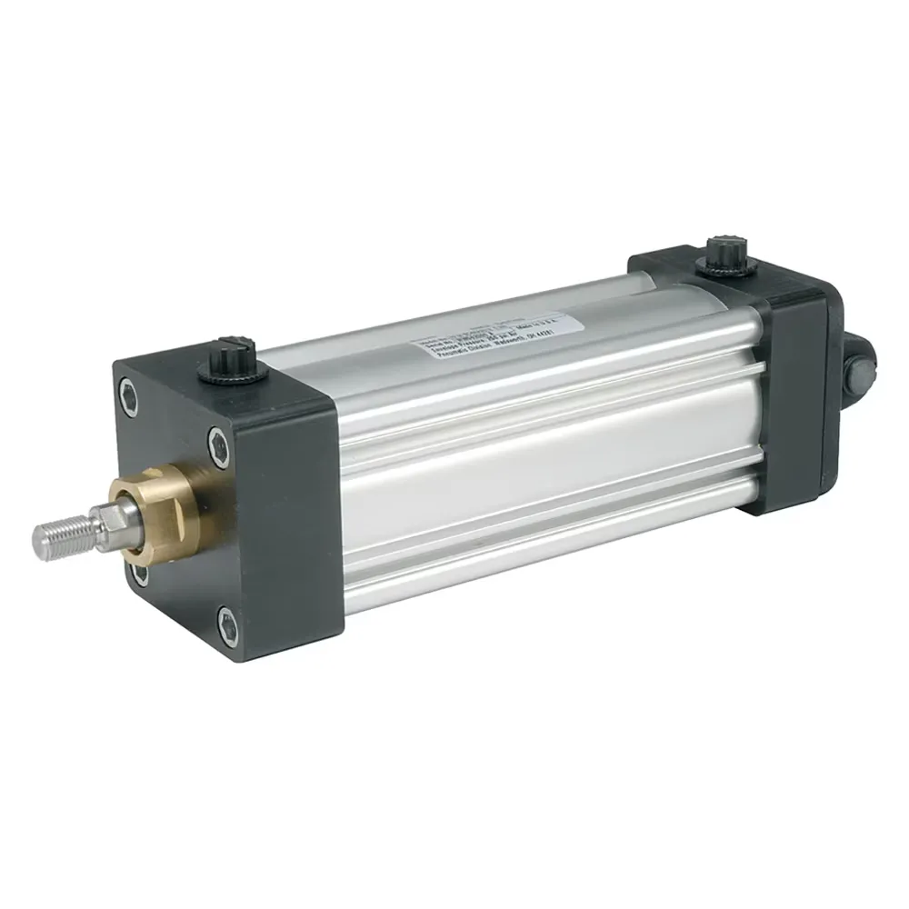
| Comparison Criteria | Hydraulic Cylinders | Pneumatic Cylinders | What to Consider When Selecting |
|---|---|---|---|
| Working Fluid | Use hydraulic fluid permitted by the equipment; hydraulic oil is common | Use compressed air that meets the model’s requirements | Refer to the nameplate and technical data; do not rely on the appearance of the fittings |
| Operating Pressure | Many industrial hydraulic circuits can operate at pressures higher than those of standard factory air sources | Depends on on-site air supply, pressure regulation, and model limitations; operating pressure may drop during operation | Compare the available pressure at the cylinder ports during load operation |
| Output Force | When available pressure is high, even a smaller cylinder bore may produce significant thrust or pulling force | If force is insufficient at a given air pressure, a larger effective area or a redesign of the mechanism is usually required | Verify the extension thrust, retraction pulling force, and mounting dimensions separately |
| Motion Control | Affected by supply and return oil lines, valves, load, and feedback methods | Air compression and exhaust resistance affect speed and stopping points; Position feedback can be configured as needed | Distinguish between full-stroke operation, intermediate positioning, and hold-after-stop |
| Supporting Equipment | Verify hydraulic pumps, reservoirs, valves, filters, and supply/return lines | Verify compressors or existing air sources, air treatment, valves, and exhaust paths | Consider the space occupied by the cylinder body separately from that occupied by the supporting system |
| Maintenance Focus | Check for external leaks, fluid contamination, seals, filter elements, and hoses | Check for air leaks, moisture, air quality, filtration, and exhaust components | Assess maintenance accessibility, spare parts availability, and the impact of downtime |
For example, lightweight material-stopping mechanisms typically only require timely extension, retraction, and reaching both end positions; in such cases, it is sufficient to first verify whether the cylinder can meet these requirements. Conversely, if a narrow clamping fixture requires high thrust within a very limited installation width, first verify the cylinder bore and available pressure of the hydraulic solution. The initial requirements for these two types of tasks differ, so there is no need to decide in advance which technology is “better.”
How Hydraulic and Pneumatic Cylinders Produce Linear Motion
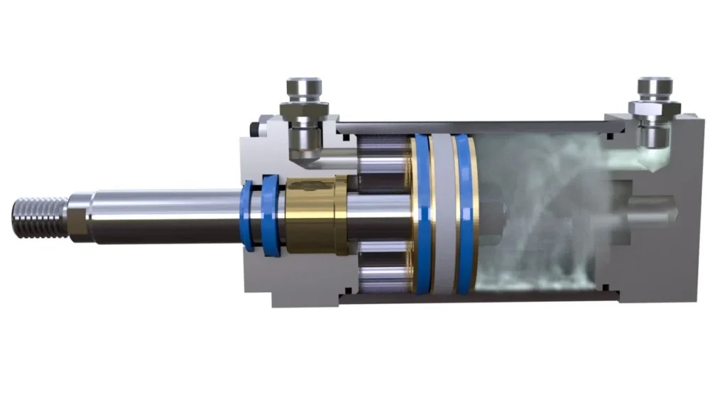
A piston is a component that moves within a cylinder when subjected to pressure; the piston rod transmits its force and displacement to an external mechanism. The cylinder bore is the inner diameter of the cylinder barrel, which determines the size of the piston’s total pressure-bearing surface. Take a common single-rod, double-acting cylinder as an example: the piston rod extends from only one end, and both extension and retraction are pressure-driven—fluid or air enters on one side, while the medium is expelled on the other; once the direction is reversed, the cylinder moves in the opposite direction. A directional control valve is the component that switches between the inlet and outlet flow paths.
The difference lies in the fact that in common hydraulic systems, the discharged hydraulic fluid is returned to the reservoir or circuit for continued use; in pneumatic systems, the discharged air is typically vented to the atmosphere via a valve. There are also single-acting configurations, where the cylinder is pressure-driven in only one direction and returns to its original position in the other direction via a spring, gravity, or other external force. For example, a spring-return stop cylinder extends when pressurized; whether it returns to its intended position after the drive pressure is removed depends on whether the spring can overcome the external forces and resistance present at that moment. When reviewing equipment diagrams, first confirm which side provides the drive, where the medium is discharged, and what mechanism is used for the return stroke; do not determine the operating mode based solely on appearance or the number of ports.
How to Compare Cylinder Force for the Same Load Requirement
Start with Effective Area and Actual Chamber Pressure
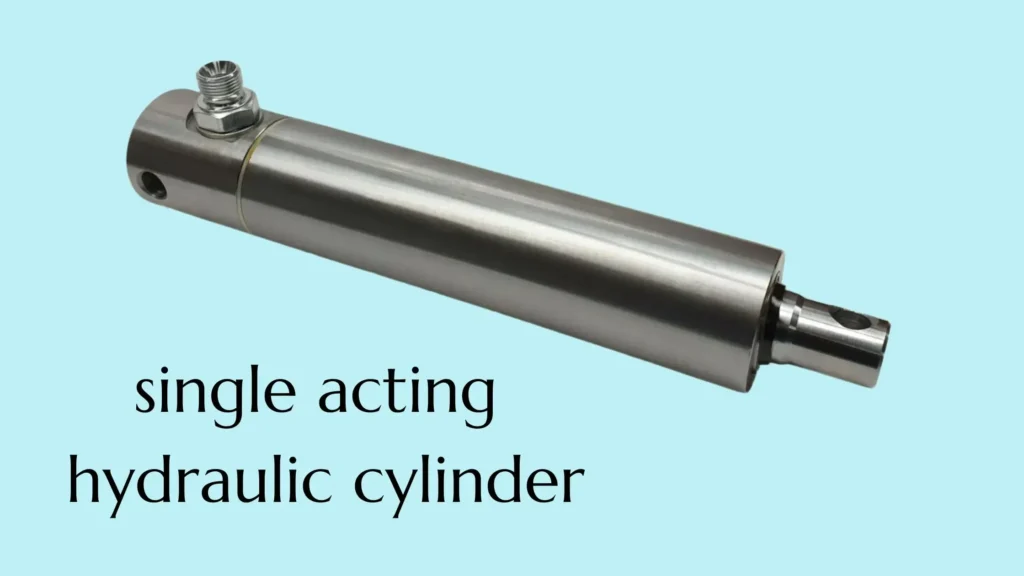
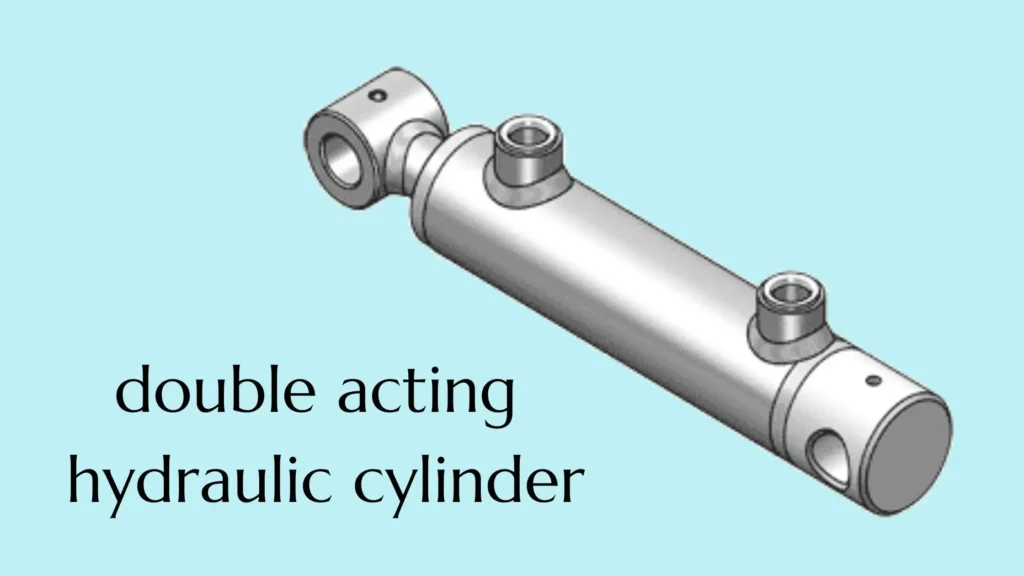
The effective area is the area of an oil or gas chamber whose pressure is used to generate an axial force. For a common single-rod, double-acting cylinder, on the rodless side, no rod passes through the piston face, so the total area is A₁ = πD² ÷ 4; on the rod side, the effective area must account for the rod’s cross-sectional area, so it is A₂ = π(D² − d²) ÷ 4. D is the cylinder bore diameter, and d is the rod diameter. At the same inlet oil or air pressure, the effective area on the rod side is smaller; therefore, when the pressure on the other side is negligible, the theoretical retraction force is lower than the theoretical extension thrust.
During extension, the theoretical net force (neglecting friction) is pressure in the rodless chamber × A₁ − pressure in the rod chamber × A₂; during retraction, it is the force on the rod side minus the opposite force on the rodless side. The pressures here are gauge pressures, i.e., readings relative to atmospheric pressure. Back pressure is the pressure generated on the discharge side by valves, piping, or throttling, and it offsets a portion of the output. Since the cross-sectional areas on both sides differ, one cannot simply subtract the two pressure readings and then arbitrarily multiply the result by an area. While the basic mechanics of both types of cylinders are the same, actual calculations must also account for friction and operating conditions.
Separate an Equal-Size Comparison from an Equal-Load Comparison
Given the same cylinder bore, rod diameter, and pressure in both chambers—and assuming factors such as friction are negligible—the theoretical net force produced by both cylinders is the same. Hydraulic cylinders can often generate greater force with a smaller bore, typically because the system used can provide a higher operating pressure. The pressures and dimensions listed below are assumptions used to illustrate the calculations; they do not represent typical pressure ranges, product ratings, or recommended specifications.
Assume that both cylinders have a bore diameter of 63 mm and a rod diameter of 25 mm, with a total effective area of approximately 3,117.2 mm² and a rod-side effective area of approximately 2,626.4 mm². Fluid or gas is supplied to one side at the given pressure, while the gauge pressure on the opposite side is approximately zero; friction is temporarily disregarded. 1 MPa (megapascal) = 1 N/mm², 1 kN (kilonewton) = 1,000 N.
| Assumed Operating Conditions | Drive Chamber Pressure | Theoretical Extension Thrust | Theoretical Retraction Tension |
|---|---|---|---|
| Pneumatic Cylinder | 0.50 MPa | 1.56 kN | 1.31 kN |
| Hydraulic Cylinder | 5.00 MPa | 15.59 kN | 13.13 kN |
If, during cylinder extension, the rod chamber reaches a gauge pressure of 0.10 MPa due to restricted exhaust, the theoretical net extension force drops from approximately 1.56 kN to approximately 1.30 kN—and that’s before accounting for friction. This explains why the theoretical output listed in the catalog appears sufficient, yet the cylinder may fail to move the load during actual operation. To troubleshoot this type of issue, first verify the actual air supply and exhaust conditions during operation; do not simply copy readings from the compressor or the main air line.
Now, let’s consider another question: If both solutions require 3 kN of extension thrust, what cylinder bore diameter is needed? Using the same assumed drive pressure as above and still ignoring back pressure and friction, divide the required thrust by the pressure to obtain the required area, then convert that to the diameter of a circle. The theoretical cylinder bore for the pneumatic solution is approximately 87.4 mm, while that for the hydraulic solution is approximately 27.6 mm. These figures are merely dimensions derived from theoretical force calculations and cannot be used directly for ordering. In practice, you must also verify candidate models, pressures in both chambers, load variations, rod stability, speed, and available space; if the critical motion is retraction, you must recalculate based on the area on the rod side.
How Compressibility and System Design Affect Speed, Positioning, and Load Holding
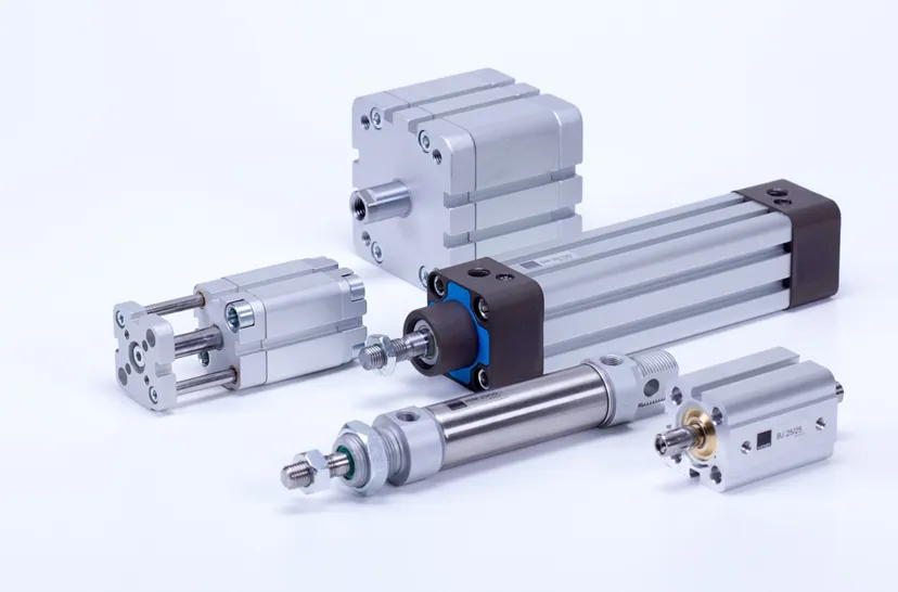
① Compare Loaded Speed, Not Free Travel
Compressibility describes the extent to which a medium changes in volume when subjected to pressure. Air tends to contract easily when pressurized; hydraulic fluid is less compressible, but the oil, hoses, and components within a hydraulic system will still undergo some deformation when subjected to force. For a typical hydraulic cylinder, under approximate conditions where leakage and fluid compression are neglected, the speed can be estimated using the formula: actual oil flow rate ÷ effective cross-sectional area of the corresponding chamber. Here, flow rate refers to the volume of fluid flowing per unit of time; when the flow rate is restricted by a pump, valve, or return line, the cylinder may not necessarily reach the target speed.
Cylinder operation is also affected by gas filling, venting, and changes in chamber pressure. For example, a cylinder that moves back and forth quickly under no-load conditions may take longer to build up sufficient pressure to move a load once a workpiece is loaded; a hydraulic cylinder may also operate slowly due to insufficient actual fluid supply. You should compare the entire duration under the same stroke, load, and direction of motion, taking into account both startup and end-of-stroke deceleration. If the flow rate of a pneumatic component is specified as the volume of air at a certain reference pressure and temperature, it cannot be directly treated as the actual volumetric flow rate within the cylinder chamber and divided by the area.
② Separate End Positions from Mid-Stroke Positioning
If the motion simply cycles between two defined end points, a cylinder equipped with appropriate limit switches and position sensors can perform many tasks. Intermediate positions, however, present a different challenge: gas behaves like an elastic spring; as the load changes, the confined gas may continue to compress or expand, causing the stopping points to shift. Hydraulic fluid is less compressible, which helps improve system stiffness—that is, its ability to resist deformation under load—but valve leakage, mechanical clearances, and sensing methods can also affect positioning accuracy.
For example, if the same feed mechanism only needs to push a workpiece to a fixed stop, a standard pneumatic cylinder may suffice; however, if it needs to stop accurately at multiple intermediate positions, a more comprehensive configuration with feedback is required. Feedback refers to a sensor transmitting the actual position back to the control system, allowing the controller to adjust the motion accordingly; pneumatic systems can also achieve positioning using displacement sensors, valves that continuously regulate flow, and position controllers. During acceptance testing, it is essential to first specify whether the workpiece or the rod end is being measured, the extent of load variation, and the allowable tolerance—it is not sufficient to simply ask which type of cylinder is more accurate.
③ Verify What Actually Holds the Load
Load holding refers to preventing unintended movement of the load after the system has stopped. Trapping air inside a pneumatic cylinder does not automatically create a reliable mechanical lock; similarly, trapping oil inside a hydraulic cylinder does not guarantee that the load will remain stationary under all conditions of leakage, line failure, or load variation. Hydraulic systems can be configured with appropriate hold-open valves or mechanical locks, while pneumatic systems can utilize rod locks or independent supports designed for the specific application. The ability to hold a stationary load and the ability to bring a moving load to a stop are two distinct requirements.
For example, for vertical loads that may fall due to a power failure, the equipment designer should specify: who bears the load during a power outage, how much movement is permitted, whether a safety stop is required, and who assumes responsibility for the load before restarting. “Pump shutdown,” “air supply cutoff,” or “valve closed” should not be considered proof that the equipment is safely secured.
Installation Requirements: Power Sources, Valves, Lines, and Space
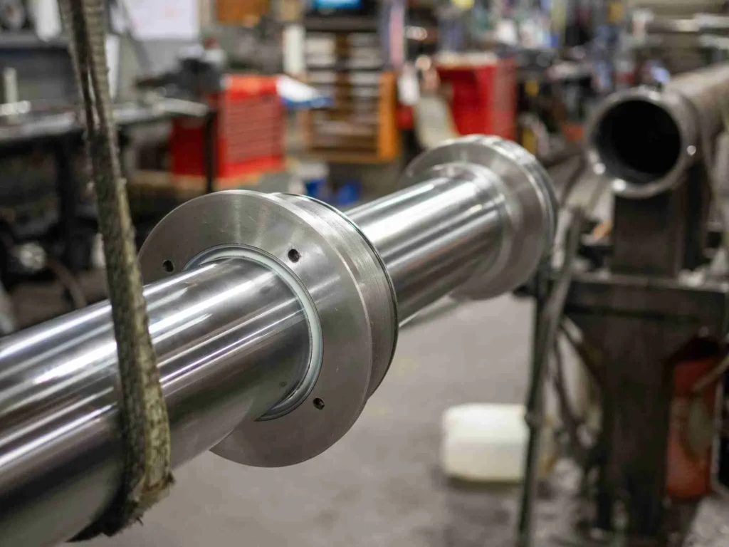
First, verify the cylinder’s mounting dimensions on the equipment drawing, then check the available space for the power supply system. For the cylinder itself, confirm the retracted and extended dimensions, mounting holes or pins, the orientation of hydraulic or pneumatic ports, clearance for fittings and piping, and whether it can be removed for maintenance. For example, if a cylinder’s bore is enlarged to compensate for thrust, it may come into contact with adjacent fixtures; in another scenario, while the hydraulic cylinder body itself may fit, it is still necessary to confirm that there is sufficient space for the valve block and hoses.
On the hydraulic side, verify the pump, reservoir, valves, and supply and return lines; if necessary, also consider cooling and filtration. On the pneumatic side, verify the available air source, pressure regulation and filtration, air drying conditions, directional control valves, and exhaust paths. Even if a shared air source or pump station is already available on-site, you must still verify the capacity margin when multiple pieces of equipment operate simultaneously. For example, while the pressure in the main air supply line may be normal when the system is at rest, the flow capacity of local piping and valves may become insufficient when several cylinders extend simultaneously. You can ask the equipment supplier to provide both the installation drawings for the operating points and the available pressure, flow rate, and connection specifications for the shared power facilities, and then determine which solution is easier to integrate.
Maintenance and Safety: Leaks, Contamination, and Stored Energy
On the hydraulic side, it is important to distinguish between external leaks and internal leaks. External leaks leave oil stains at the rod ends, fittings, or in the piping; internal leaks occur when fluid bypasses seals and flows within the system, which may not be visible from the ground. Particles and moisture in the oil can also affect valves, cylinders, and seals. For example, if a mechanism begins to lower slowly, even in the absence of oil stains, you cannot assume that the cylinder and valves are functioning properly; You can record the location, load, and oil temperature where the issue occurred, and then have maintenance personnel assess the actual circuit accordingly.
Air leaks in pneumatic systems do not necessarily leave visible traces, but they can increase air consumption and reduce pressure at the points of use; moisture, oil mist, and particles can also affect valves, seals, and the product environment. For example, when pneumatic equipment repeatedly jams, factors such as air quality, fluctuations in supply pressure, and mechanical resistance should all be considered together. For workstations near food, in spray painting, or other applications with cleanliness requirements, “not using hydraulic oil” does not automatically mean that the air supply and exhaust inherently meet environmental standards; you must still verify filtration, drying, and permissible lubrication conditions.
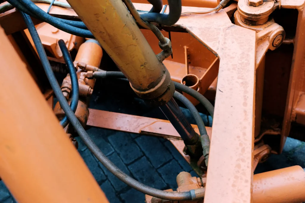
Both types of equipment may store energy: even when the power source is shut off, enclosed compressed air, residual oil pressure, air receivers, or hydraulic accumulators may still release energy; an accumulator is a component that stores hydraulic energy and releases it when needed. A lifted load also retains gravitational potential energy. During maintenance and evaluation, ensure that the equipment has clear energy isolation procedures, residual pressure verification protocols, and load-support arrangements in place; do not rely solely on the main line pressure gauge. Hydraulic fluid sprayed from a small crack can penetrate the skin; do not use your hands to locate leaks. If dangerous movement or fluid spray is detected, shut down the equipment according to established procedures and have it inspected by qualified personnel.
Total Cost of Ownership: Equipment, Energy Use, and Maintenance
Total cost of ownership refers to all related costs incurred over the same service life to perform the same work. First, establish fixed comparison criteria: daily operating time, number of cycles per hour, distance traveled per cycle, duration of load maintenance, and whether the air source or pump station is newly built or shared. After filling in these criteria, list the following for each of the two options:
- Equipment and Integration: Cylinder price, valves, mounts, piping, as well as any new or modified air supply, air treatment, or hydraulic power units required.
- Energy: Actual electricity consumption or verifiable estimates for achieving the same output, including energy used for standby, leaks, air treatment, hydraulic cooling, and other related purposes.
- Maintenance and Downtime: Spare parts such as filter elements, hydraulic fluid, seals, hoses, and valves; scheduled maintenance labor hours; and attributable downtime losses.
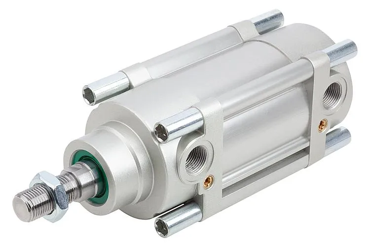
For example, if an existing compressor still has spare capacity and only a single material-stopping cylinder that operates occasionally is added, the full purchase cost of the compressor cannot be attributed to that single cylinder; however, if installing cylinders at multiple workstations necessitates additional compression capacity or air drying equipment, these incremental costs should be included. The same principle applies when hydraulic pump stations are shared. When conditions permit, record the system’s energy consumption based on the same production volume and time periods; do not use cylinder prices, the rated power on a pump or compressor nameplate, or an unverified energy-saving percentage as a substitute for comparison.
Using Compressed Air in a Hydraulic Cylinder: Compatibility Limits
Compressed air must not be introduced simply because the hydraulic cylinder’s rated pressure exceeds the supply pressure. Pressure-bearing capacity only addresses part of the question regarding the conditions the structure can withstand; it does not indicate whether the seals, lubrication, and motion control are suitable for gas. When a configuration originally designed for hydraulic fluid is converted to air, the sealing performance at low pressure, rod surface lubrication, speed, and end-of-stroke deceleration may all change; since gas stores energy when pressurized, the consequences of failure must also be evaluated separately.
Some manufacturers list air, hydraulic fluid, or other media for specific products and indicate the applicable seal configurations for each. Even if the seal material itself is compatible with air, this does not replace the need to verify the entire cylinder and circuit. For example, the fact that a hydraulic cylinder fits a pneumatic fitting does not prove that it can be reliably lubricated, operate at the expected speed, and stop safely when used with air over the long term. Specialized air-hydraulic combination units have their own media and circuit designs and cannot be used as a basis for assuming that a standard hydraulic cylinder can be directly converted to air operation.
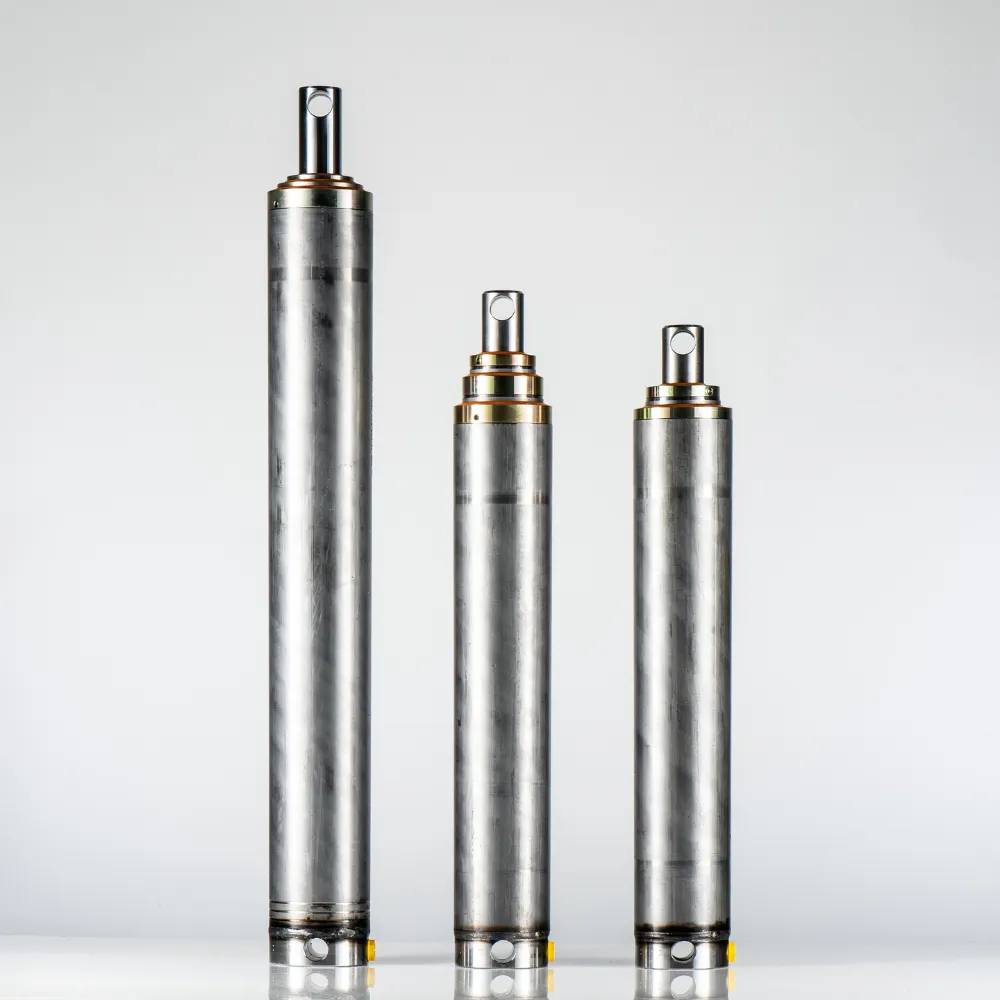
If you are evaluating an existing cylinder, first provide the manufacturer with the model number, drawings, or nameplate, as well as the intended medium, pressure, speed, cycle, installation orientation, and shutdown requirements. Ask the manufacturer to confirm the permitted media, sealing, and lubrication conditions for the entire configuration, as well as the corresponding operational and safety requirements. Without explicit confirmation specific to the model and application, you should reselect an appropriate pneumatic or hydraulic solution as needed; temporary air-filling tests to simulate operation cannot substitute for suitability verification.
When to Choose Hydraulic Cylinders and When to Choose Pneumatic Cylinders
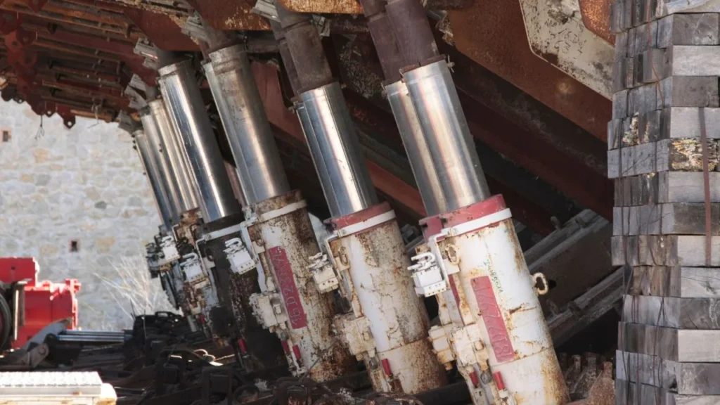
Use Your Application to Narrow the Choice
First, use push-pull force, available space, and failure modes to eliminate unsuitable options; then, use cycle time, maintenance, and cost comparisons to narrow down the remaining models. The criteria below are suitable for initial screening; meeting any single criterion in the table does not constitute a final selection decision.
| Your Application Conditions | Can Be Evaluated First | Still Needs Verification |
|---|---|---|
| Heavy-duty clamping, lifting, or pushing/pulling with limited lateral space for the cylinder | Hydraulic Cylinder | Push/pull force under the most adverse conditions, port pressure, rod stability, and load protection |
| Short-stroke material feeding, sorting, or material stopping, primarily operating at two end points | Pneumatic Cylinder | Load-carrying cycle time, end-of-stroke deceleration, actual air pressure, and margin during peak air consumption |
| Long stroke or frequent cycles | Compare both solutions simultaneously | Retracted dimensions, guidance, speed, and continuous supply capacity; do not compare only no-load operations |
| Requires intermediate positioning or vertical holding | Compare complete solutions with specific controls and protections | Positioning error, allowable displacement, load direction, and response after air or pump shutdown |
| Workstations sensitive to hydraulic fluid contamination, or located in dusty, humid, or washdown environments | Screen based on contamination consequences and available protective measures | Air source and exhaust quality, consequences of hydraulic fluid leaks, protection, temperature, and maintenance conditions |
| Existing stable air or hydraulic source; desire to minimize new equipment | First evaluate solutions that can reuse existing facilities | Pressure, flow rate, interfaces, and incremental operating costs when multiple devices operate in parallel |
For example, a short-stroke stopper on a packaging machine and a heavy-duty tilting fixture in the same workshop may require different types of cylinders. For the former, the primary considerations may be cycle time and air supply margin; for the latter, it is also necessary to calculate the actual force exerted on the cylinder by the load at various angles and to verify the thrust and power-off protection at the most unfavorable position. There is no need to impose the same spatial or cost trade-offs on every workstation simply to standardize the drive type.
Prepare a Specification Your Supplier Can Check
When submitting evaluation materials, clearly specify at least four sets of information: Operation (thrust and pull force, speed, stroke, cycle time, and dwell time); Installation (orientation, mounting dimensions, force direction, and environment); Supply (available pressure and flow rate during operation, existing power systems, and valves); Acceptance (positioning error, allowable displacement, and expected state after a power interruption). If actual measured values are not yet available, specify the estimation conditions to avoid treating unknown variables as if they were already satisfied.
If these conditions point toward a hydraulic solution, submit the operating conditions table, installation drawings, and the original cylinder serial number to GY Hydraulic to discuss the hydraulic cylinder’s dimensions, operating mode, and selection requirements. Once both solutions meet the mandatory conditions, compare the actual total costs based on the same production volume and service life.
Choosing a Trusted Hydraulic Cylinder Manufacturer
From standard hydraulic cylinders to custom solutions, we help you improve equipment performance, delivery reliability, and batch consistency
Explore Rivmate Cases

Hey There, I'm Melody!
We are a hydraulic cylinder manufacturer. For over 20 years, we have focused on producing reliable hydraulic cylinders. Need a hydraulic cylinder solution? Feel free to contact us.