
Home / What Is Column Load in Hydraulic Cylinders?
What Is Column Load in Hydraulic Cylinders?
- Author: GY Hydraulic
- 20+ Years of Manufacturing
The column load of a hydraulic cylinder refers to the compressive load borne by the piston rod along its own axis. When a hydraulic cylinder pushes or supports a load, the piston rod acts like a column under compression. If the load is too great, a slender piston rod may lose stability and bend sideways; this phenomenon is known as buckling.
Therefore, when selecting a hydraulic cylinder, you must not only consider the amount of thrust it can generate but also ensure that the piston rod can stably withstand this force. Particularly in long-stroke applications, sufficient thrust does not guarantee that the piston rod will not bend. This article will help you understand column load, as well as how the piston rod diameter, extension length and mounting method affect load-bearing capacity.
Table of Contents
What Is Column Load in Hydraulic Cylinders?
The column load of a hydraulic cylinder refers to the compressive load borne along its own axis when the piston rod acts as a compression column. Put simply, when you use a hydraulic cylinder to lift a heavy object or push a workpiece forwards, the load in turn exerts pressure on the piston rod. If the piston rod is relatively slender, excessive pressure may cause it to lose stability and bend sideways; this is known as buckling. The term ‘column’ here describes the manner in which the force is applied; it does not imply that the hydraulic cylinder must be installed vertically. A hydraulic cylinder pushing a workpiece horizontally may equally be subject to a column load. To determine whether this issue needs to be considered, you must first ascertain whether the piston rod is under compression or tension; a purely axial tensile condition does not constitute a compression buckling issue.
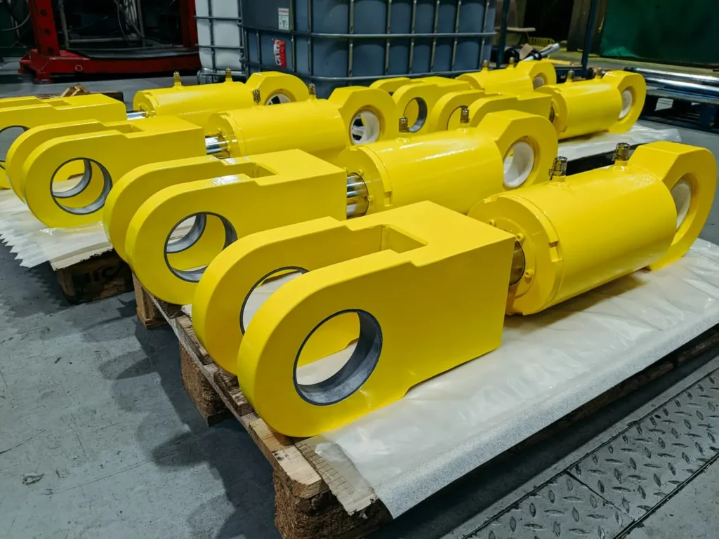
Axial Compression vs. Hydraulic Push Force
Axial compression describes how the piston rod is loaded; hydraulic thrust describes how much pushing force the hydraulic pressure can generate. Whilst the two are directly related, the ‘maximum available thrust’ must not be taken directly as the actual column load at any given moment.
For a standard single-rod hydraulic cylinder, when back pressure from the return line and friction are neglected, the theoretical thrust in the extension direction can be calculated as ‘pressure × piston area’. The actual output must also account for the counterforce generated by the back pressure in the rod chamber, as well as frictional resistance from seals and other components. When reviewing product specifications, you should verify the pressure and calculation conditions corresponding to the thrust.
For example, under simplified conditions where friction and inertia are ignored, if you need approximately 20 kN to slowly push a workpiece, the compressive load transmitted by the piston rod will also be approximately 20 kN, even if the hydraulic cylinder’s maximum available thrust is higher. However, should the workpiece become jammed, continued oil supply may cause the pressure to rise, thereby increasing the compressive load on the rod. Consequently, buckling checks must take into account not only the average load during normal operation but also the maximum compressive load that the system may exert.
Column Strength vs. Rated Cylinder Force
Column strength refers to the ability of a compressed structure to resist buckling; rated cylinder force typically denotes the output capacity of a hydraulic cylinder under specified pressures and conditions. A sufficient rated force does not automatically mean that the piston rod will remain stable under your specific stroke and mounting conditions. Buckling resistance is also influenced by the rod diameter, compressed length, material, mounting method and load guidance conditions.
You must also distinguish between the ‘critical buckling load’ and the ‘allowable compressive load’. The former is the theoretical load at which buckling begins and cannot be used directly as an upper limit for routine operation; the latter should be calculated using applicable methods and incorporating a safety factor. If the manufacturer provides an allowable load that already includes a safety factor, you should verify the conditions under which it applies, rather than using the two values interchangeably.
When selecting a cylinder in practice, you can provide the supplier with the maximum compressive load, maximum working extension, piston rod diameter, mounting arrangements for the cylinder body and rod ends, and whether the load is externally guided, and request verification of the permissible compressive load for that configuration.
Why a Long Extended Rod Can Buckle Before the Cylinder Stalls
Once the piston rod is extended, the length lacking lateral support typically increases, making it more susceptible to bending under the same compressive load. You can think of it as a ruler subjected to compressive force along its length: it is less likely to bend when shorter, but more likely to arch when extended to a greater length. The effective buckling length of a hydraulic cylinder also depends on the mounting and support conditions.
When a hydraulic cylinder stops because it ‘cannot push any further’, this usually means that, at the current available pressure, the output force is no longer sufficient to overcome the resistance. However, buckling is determined by structural stability. If the buckling load of the piston rod is lower than the compressive force the system can generate, it may buckle before the pressure reaches the system’s limit. The relief valve limits the pressure, and its set point must be matched to the structure’s permissible load-bearing capacity.
One can first verify the buckling resistance at the maximum working extension position, and then check whether the load varies over the full stroke.
When Does Column Loading Become a Design Risk?
When the compressive load on the piston rod approaches or exceeds the permissible load under the current installation conditions, the rod load becomes a design risk. Long stroke, small rod diameter, high thrust and insufficient support all increase this risk. If lateral forces or impact are also present, the piston rod may buckle before the hydraulic cylinder reaches its rated thrust; in other words, it may lose stability under compression and bend sideways. Throughout the entire working stroke, the actual compressive load must always remain below the permissible load capacity for the corresponding position, whilst maintaining an appropriate safety margin.
Long Stroke and Small Rod Diameter
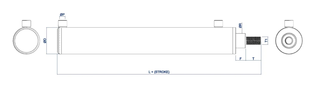
When a long stroke is combined with a small rod diameter, you must pay particular attention to buckling resistance. Generally, the longer the piston rod extends, the more prone it is to bending under compression; conversely, a smaller rod diameter results in weaker resistance to bending. Consequently, whilst the same thrust may pose no problem for a short, thick piston rod, it may cause instability in a slender piston rod. Parker’s design documentation also explicitly warns that column instability or piston rod buckling may occur when the stroke is excessively long relative to the rod diameter.
For example, the buckling resistance should be re-verified after altering the stroke or adding a rod-end extension. If the piston rod is subjected only to axial tensile forces under the relevant operating conditions, buckling is not a concern; however, the tensile strength and the load-bearing capacity of the connecting components must still be verified.
High Push Force at Full Extension
When approaching full extension, the piston rod is typically in a less favourable support condition. If a significant thrust is still required at this point, both conditions—‘long compressed length’ and ‘high compressive load’—will be present simultaneously. Such operating conditions warrant particular attention, for example, where a material-feeding mechanism must still overcome significant resistance at the end of its stroke, or where a press-fitting operation is scheduled whilst the piston rod is near full extension.
You should verify the maximum compressive load that may occur at this position, rather than merely the force required to move the workpiece under normal conditions. If the workpiece becomes jammed, the pressure inside the cylinder may continue to rise. Therefore, when calculating based solely on normal loads, reliable measures must be in place to ensure that the actual pressure does not exceed the pressure on which the calculation is based. Bosch Rexroth’s selection guidelines also explicitly stipulate this requirement.
It is recommended that you provide the supplier with the maximum working extension, the thrust required at that position, and the maximum pressure the system is capable of exerting for verification. However, full extension is not necessarily the most hazardous position within the entire stroke. If the mechanism generates greater compressive forces at an intermediate position, you must also check that position.
Unsupported Length and Mounting Geometry
Unsupported length refers to the length of the compressed section lacking effective lateral restraint. The ‘effective buckling length’ is also used in calculations; this takes into account whether the ends are free to rotate, as well as the effects of the mounting position and guidance conditions. Therefore, the stroke of a hydraulic cylinder, the exposed piston rod length and the effective buckling length cannot be equated directly. The manufacturer’s buckling calculations will adjust the relevant lengths according to the mounting method and whether the load is guided.
For example, two hydraulic cylinders with identical bore diameter, rod diameter and stroke—one mounted with a head flange and the other with a tail pin—will have different support conditions and may therefore have different permissible compressive loads.
Side Load, Misalignment and Dynamic Shock
A lateral load is a force applied to the side of the piston rod; misalignment refers to a situation where the axis of the hydraulic cylinder is not correctly aligned with the direction of load movement. These factors cause the piston rod to be subjected to bending whilst under axial compression, further amplifying any existing slight deflection. Standard hydraulic cylinders should not be assumed to act as lateral guides for workpieces; Parker also recommends using mechanical guides to prevent lateral loads from being transmitted to the piston rod or piston.
For example, even if the slide you are pushing has independent guide rails, but the direction of the guide rails is not parallel to the hydraulic cylinder’s axis, the slide may still exert lateral pressure on the piston rod during movement. During design review, the alignment relationship throughout the full stroke should be checked, as well as whether pin or joint connections have the required degrees of rotational freedom, rather than merely confirming that assembly is possible in the retracted position.
Dynamic impacts result from sudden collisions, jamming or rapid starts and stops, and may cause instantaneous loads to exceed normal operating values. If the equipment is subject to impact or emergency stop conditions, you must provide the supplier with details of the movement speed, moving mass, deceleration method and potential jamming scenarios to verify the peak forces. Repeated impacts may also lead to fatigue issues.
Which Cylinder Dimensions Control Column Strength?
The key dimensions affecting the buckling resistance of a hydraulic cylinder are the piston rod diameter and the effective buckling length. Generally, the larger the rod diameter, the less prone it is to bending; conversely, the longer the effective buckling length, the more susceptible it is to buckling. The stroke, retracted installation length and rod end extension affect the load-bearing capacity by altering the relationship between the length of the compressed structure and its supports. The modulus of elasticity of the material is also important, as it reflects the material’s ability to resist elastic deformation.
Piston Rod Diameter
The piston rod diameter directly affects its ability to resist bending. For a uniform solid circular rod, assuming the material, effective length and support conditions are identical, and provided the Euler elastic buckling model applies, the theoretical critical buckling load is proportional to the fourth power of the rod diameter. The critical load referred to here is the load at which buckling theoretically begins; it is not the permissible working load.
For example, whilst the aforementioned conditions remain unchanged, increasing the rod diameter from 40 mm to 50 mm results in the theoretical critical buckling load becoming approximately 2.44 times the original value, calculated as ‘(50 ÷ 40) to the fourth power’. This example illustrates that increasing the rod diameter may significantly improve the buckling resistance of a slender compression member; however, it cannot be directly concluded that the rated load capacity of the entire hydraulic cylinder has increased by a factor of 2.44.
When verifying the figures, you should also specify whether the piston rod is hollow and whether there are any lengthy sections with reduced diameter. For hollow rods, both the outer and inner diameters must be taken into account; rods with significant changes in cross-section cannot simply be calculated as if they were solid circular rods of uniform diameter throughout. Relying solely on the nominal rod diameter stated in the product name may lead to the omission of structural details that affect load-bearing capacity.
Exposed Rod and Effective Column Length
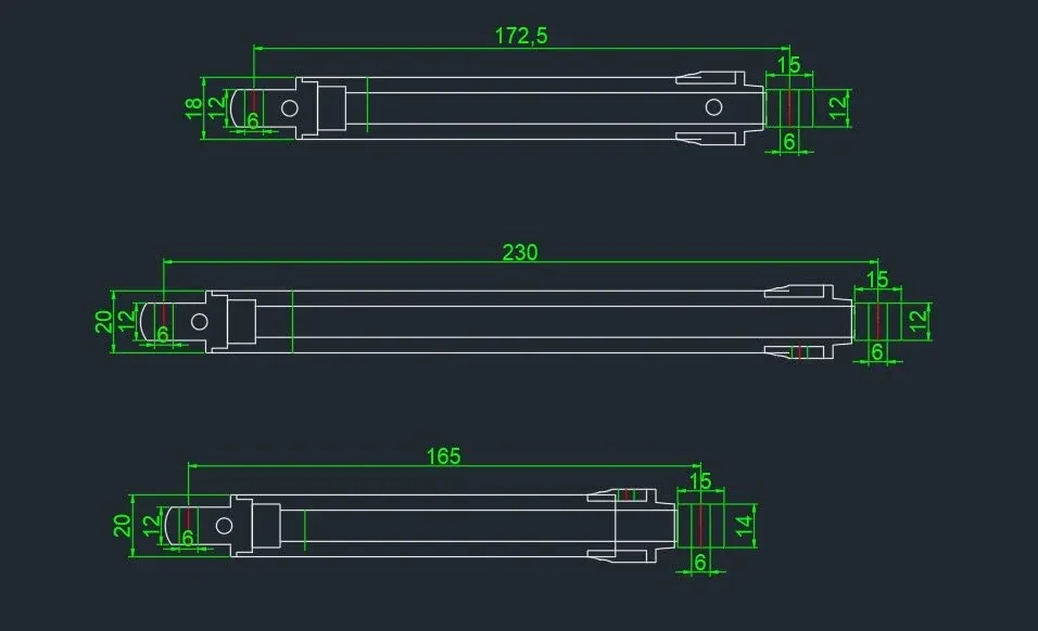
The exposed rod length is the actual length by which the piston rod protrudes from the cylinder head at a given operating position. The effective buckling length, on the other hand, is the equivalent length used for stability calculations; it also takes into account whether the mounting end can rotate, as well as the support positions and guidance conditions.
Under the ideal Euler model, and assuming all other conditions remain constant, the theoretical critical buckling load is inversely proportional to the square of the effective length. In other words, if the effective length is doubled, the theoretical critical buckling load will be reduced to a quarter of its original value. This relationship explains why, after lengthening the rod end or altering the mounting position, a re-verification is required even if the rod diameter and pressure remain unchanged.
You can mark the maximum working extension position, the cylinder body support points, the rod end connection points and the external guide positions on the installation drawing, so that the supplier can determine the calculation length accordingly. For hydraulic cylinders where the entire assembly is subject to bending, the combined effect of the cylinder barrel and the piston rod may also need to be taken into account.
Stroke Length and Closed Length
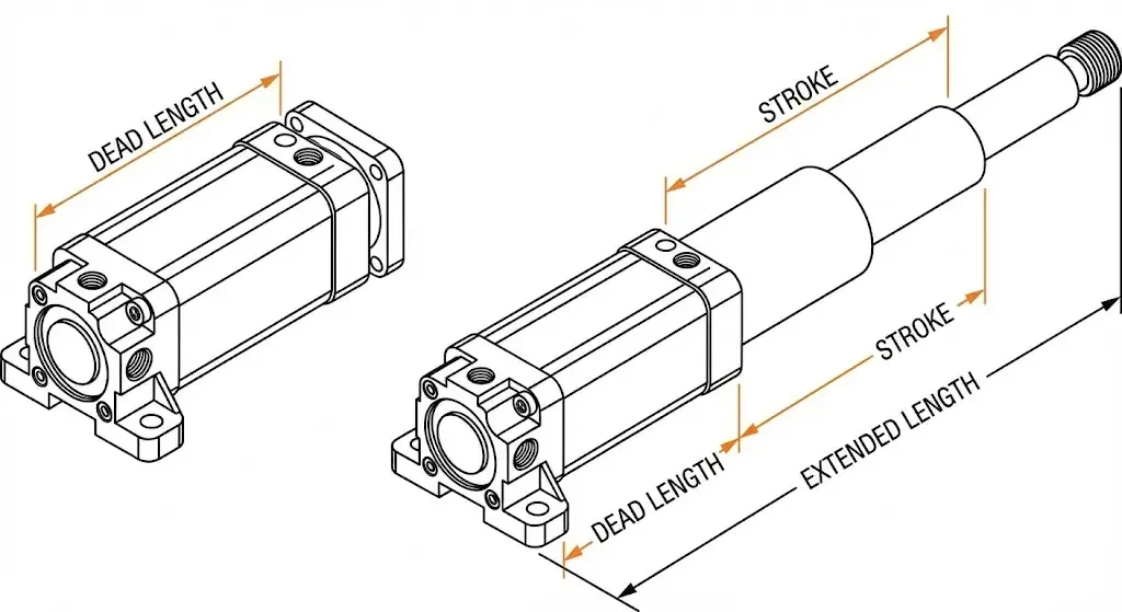
Stroke refers to the distance travelled by the piston rod from fully retracted to fully extended; the retracted installation length (Closed Length) typically refers to the distance between specified installation reference points when the hydraulic cylinder is fully retracted. As reference points may vary between different product drawings, you should first confirm the measurement location. For common hydraulic cylinders with pin-mounted ends, if the retracted length is measured between the centres of the two pins, the centre-to-centre distance when fully extended is equal to ‘retracted centre-to-centre distance + stroke’. For example, with a retracted centre-to-centre distance of 800 mm and a stroke of 500 mm, the centre-to-centre distance when fully extended is 1,300 mm. This is the installation geometry, which is still not equivalent to the determined effective buckling length. When replacing a hydraulic cylinder, you should simultaneously verify the stroke, retracted installation length and rod end extension dimensions, and specify whether an extended rod is required. The manufacturer’s selection method will also take into account changes in installation length and piston rod extension.
Rod Material and Modulus of Elasticity
When selecting materials, it is important to distinguish between two concepts: yield strength refers to the stress level at which a material begins to exhibit significant permanent deformation; modulus of elasticity refers to a material’s ability to resist deformation within the elastic range. Higher strength does not necessarily imply smaller elastic deformation under the same load.
For slender piston rods governed by elastic buckling, the modulus of elasticity is a critical material parameter. The yield strengths of common steels can vary considerably, but their moduli of elasticity are usually quite similar. Therefore, simply replacing ordinary steel with higher-strength steel, without changing the rod diameter or effective length, will not generally result in a proportional increase in the elastic buckling load commensurate with the increase in strength. If the piston rod is short and thick, and has already entered the inelastic deformation stage prior to failure, the influence of yield strength becomes more pronounced; in such cases, the ideal Euler model cannot be directly applied.
How Do Mounting Conditions Change Buckling Capacity?
Mounting conditions alter the effective buckling length of a hydraulic cylinder by restricting the lateral movement and end rotation of the compressed structure, thereby affecting its buckling resistance. Even with the same rod diameter, material and stroke, changing the mounting method may result in a different compressive load capacity.
Fixed, Pinned, and Guided End Conditions
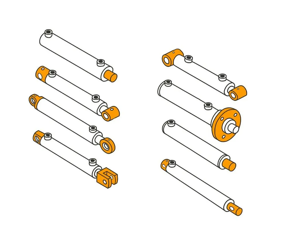
In buckling analysis, a fixed end restricts both lateral displacement and rotation at the end; a pinned end restricts lateral displacement but allows rotation within the plane of analysis. The term ‘fixed’ here refers to a mechanical constraint.
A guided end requires further clarification as to which movements it restricts. Mechanical guides typically allow the load to move in the working direction whilst restricting lateral displacement; however, whether the rod end can rotate depends on the connection method. For example, although a slide block has guide rails, if the piston rod is connected to the slide block via a pin, the rod end may still rotate and cannot therefore be treated as a fully fixed end in the calculation.
Effective Length Factors
The effective length factor K is used to convert the effect of end constraints into a calculated length, i.e. ‘effective buckling length = K × the compressed length in the selected model’. Under the ideal uniform compression member model, K = 1 when both ends are hinged; approximately 0.7 when one end is fixed and the other is hinged; 0.5 when both ends are fixed; and 2 when one end is fixed and the other is free. These values correspond to specific ideal constraints.
For example, assuming the material, cross-section and actual length remain unchanged, and when the Euler elastic buckling model is applied, a reduction in K from 1 to 0.5 results in the theoretical critical buckling load increasing to four times its original value. However, this does not mean that simply replacing a pin with a flange will enable the hydraulic cylinder to safely bear four times the load in practice. The cylinder body, rod end and frame must genuinely provide the corresponding constraints, and the calculation must also take safety margins into account.
Pivot Mounts vs. Rigid Mounts
Pivot mounts, such as ear-type pins or trunnion mounts, allow the hydraulic cylinder to change angle in tandem with the movement of the mechanism, making them suitable for applications such as driving swing arms and tilting mechanisms. Their value lies in ensuring that the applied force is transmitted as closely as possible along the axis of the hydraulic cylinder, thereby reducing lateral compression of the piston rod caused by the mechanism’s movement. Standard pins typically permit pivoting within a single plane; if the movement involves deflection outside this plane, a connection with corresponding self-aligning capability must also be provided.
Rigid mounts, such as flange or foot mounting, are better suited to linear thrust tasks where the axis is fixed. They provide strong constraints but also require the mounting to be centred and the frame to be sufficiently rigid. Foot mounting may also generate a torque that causes the cylinder body to rotate about the mounting point; therefore, a ‘rigid mount’ does not automatically equate to an ideal fixed end.
You should first select the mounting method based on the mechanism’s motion trajectory, then verify the buckling resistance. If the load moves along an arc but the cylinder body is forcibly fixed to increase the degree of constraint in the calculation, this may actually introduce additional bending. For oscillating mounts, you should also check whether the rod-end connections can accommodate the oscillation and whether angular interference occurs throughout the full stroke.
Why Load Guidance Must Be External to the Cylinder
For standard hydraulic cylinders, lateral load constraints should be borne by external guide rails, guide posts or mechanical pivot points. The guide sleeves and piston guide elements inside the cylinder primarily maintain internal motion relationships; this does not imply that the hydraulic cylinder possesses the lateral load-bearing capacity to replace mechanical guide rails. Parker’s installation instructions also require that loads be effectively guided to avoid applying lateral forces to the rod guides and piston support areas.
For example, if you use a hydraulic cylinder to push a clamping plate, and the clamping plate is connected only at the rod end, the tilting torque generated by workpiece eccentricity may be transmitted to the piston rod. By using suitable external guide posts, these posts bear the lateral forces and tilting torque, whilst the hydraulic cylinder primarily provides axial thrust. However, the guide posts and the hydraulic cylinder must be correctly aligned; otherwise, the guiding structure may also force the piston rod to bend.
When reviewing the design, you can trace the force path and ask: When the clamping plate is subjected to lateral thrust or tilts, which component actually bears the load? If the answer is solely the piston rod, the guidance scheme needs to be reassessed. Actuators equipped with dedicated guidance mechanisms, for which the manufacturer explicitly specifies lateral force and torque ratings, may be used in accordance with those specifications.
How Is Hydraulic Cylinder Column Load Calculated?
When verifying the axial load on a hydraulic cylinder, you must first determine the maximum compressive force that the piston rod is likely to withstand, then calculate or consult a table to determine the permissible load capacity under the relevant installation conditions, and finally compare the two. You must ensure that ‘the maximum compressive load does not exceed the permissible load’, rather than simply confirming that the hydraulic thrust is less than the theoretical buckling load. The theoretical buckling load represents the limit at which the structure begins to lose stability.
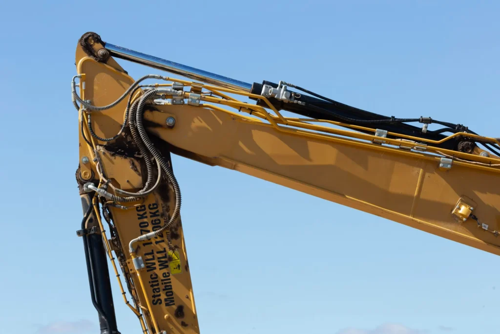
① Establish the Maximum Compressive Load
Firstly, you must determine the maximum compressive load that may occur throughout the entire working cycle, including normal thrust, workpiece jamming, and forces caused by acceleration, deceleration or external loads. Do not rely solely on the average pressure during normal operation, nor should you treat the hydraulic cylinder’s rated pressure as the actual working pressure.
For a standard single-rod hydraulic cylinder, in the extended direction and neglecting friction and inertia, the net hydraulic thrust can be expressed as: Net hydraulic thrust = pressure in the rodless chamber × piston area − pressure in the rod chamber × annular area
Here, the piston area is the full cross-sectional area of the piston; the annular area is the piston area minus the cross-sectional area of the piston rod. If the return line back pressure can be neglected, the formula simplifies to: Theoretical thrust = non-rod chamber pressure × piston area
When using MPa and mm², the result is expressed in N, as 1 MPa = 1 N/mm². Manufacturers’ thrust tables are also typically based on pressure and effective area. For example, assuming a bore diameter of 63 mm, a maximum rod chamber pressure of 16 MPa, and negligible return line back pressure:
Piston area = 3.1416 × 63 × 63 ÷ 4 ≈ 3,117.2 mm²
Theoretical thrust = 16 × 3,117.2 ≈ 49,875 N ≈ 49.9 kN
This is merely a calculated value for the assumed operating conditions. If external impacts, pressure surges or special circuits are present, you will also need to verify the actual peak compressive load separately. Furthermore, do not add the load already used to calculate the required pressure to the hydraulic thrust again.
② Determine the Effective Unsupported Length
Next, you need to determine the effective buckling length, which is the calculated length that takes into account the mounting and support conditions. In the simplified compression member model, the calculation is as follows: Effective buckling length = Effective length factor × Compressed length used in the model.
The effective length coefficient reflects the influence of end constraints on buckling. The compressed length used in the model must not be taken as the hydraulic cylinder stroke without careful consideration, nor should the effective buckling length be equated directly with the exposed piston rod length. Manufacturers will determine the appropriate calculated length based on the installation method, rod end connections and load guidance conditions.
You may prepare an installation drawing showing the maximum working extension position, indicating the cylinder mounting points, rod end connections, external guidance and rod end extension. The maximum extension position usually requires particular attention; however, if the mechanism experiences greater compressive loads at other positions, you should also compare the loads at those positions with the load-bearing capacity to identify the position with the smallest safety margin.
③ Apply Euler’s Buckling Principles
For slender, approximately uniform compression members subjected to axial compression along their centreline, and which remain within the elastic range at the point of buckling, the critical buckling load can be estimated using Euler’s formula: Theoretical critical buckling load = π² × modulus of elasticity × moment of inertia of the cross-section ÷ effective buckling length².
The theoretical critical buckling load is the load at which the model begins to lose stability. The modulus of elasticity represents the material’s ability to resist elastic deformation; the section modulus represents the cross-section’s ability to resist bending. For a solid circular member, the section modulus = π × member diameter⁴ ÷ 64. For hollow members, both the internal and external diameters must be taken into account.
Continuing with the previous example, assume a solid rod with a diameter of 40 mm, a modulus of elasticity of 210,000 N/mm² and an effective buckling length of 1,500 mm. The cross-sectional moment of inertia is calculated as: 3.1416 × 40 × 40 × 40 × 40 ÷ 64 ≈ 125,664 mm⁴.
Substituting these values into Euler’s formula, the theoretical critical buckling load is: 3.1416 × 3.1416 × 210,000 × 125,664 ÷ (1,500 × 1,500) ≈ 115,800 N ≈ 115.8 kN. ** Units must be standardised in the calculation: modulus of elasticity in N/mm², length in mm, and section modulus in mm⁴; the result is in N; divide by 1,000 to convert to kN.
This result should only be used as an estimate based on the assumed compression member model. If the structure is short and stout, exhibits significant eccentricity or lateral forces, or if the cylinder barrel and piston rod are jointly subjected to bending, the simple Euler model may be insufficient to describe the actual conditions; in such cases, appropriate non-elastic buckling or global structural analysis methods must be employed.
④ Compare Calculated Capacity With Manufacturer Charts
Once the preliminary calculations are complete, you should cross-reference the piston rod selection charts or buckling load charts for that product series to verify the rod diameter, mounting method, length definition and load guidance conditions. Pressure–thrust tables only indicate the force a hydraulic cylinder can generate; they are not a substitute for buckling selection charts. Parker’s selection guides also treat thrust selection and piston rod compression verification as separate processes.
Before consulting the charts, first confirm whether the values shown are ‘critical loads’ or ‘allowable loads’ that already incorporate a safety factor. If your manual calculation differs from the chart, do not simply select the higher value. You should first check that the calculated length, end constraints and safety factor are consistent, and verify that the chart takes into account the actual structure of the hydraulic cylinder. For extended rods or special mounting configurations that fall outside the scope of the charts, you should not extrapolate the curves beyond their limits.
⑤ Apply an Appropriate Safety Factor
If the method of dividing the critical load by the safety factor is used, the calculation is as follows: Permissible load = Theoretical critical buckling load ÷ Safety factor. When determining whether the requirements are met, ensure that: Maximum compressive load ≤ Permissible load.
The maximum compressive load is the greatest axial compressive force that may occur under design conditions. The safety factor must be consistent with the calculation method, application requirements and the manufacturer’s specifications. For example, specific calculation notes from Bosch Rexroth discuss a catalogue-recommended value of 3.5, as well as a selection range of no less than 2.5 under certain conditions; this forms part of their method’s specifications and cannot be directly applied to all hydraulic cylinders or simple Euler calculations.
For the purposes of a demonstration calculation only, assuming a safety factor of 3 is used in this example, then the permissible load = 115.8 ÷ 3 ≈ 38.6 kN. The maximum thrust calculated earlier is approximately 49.9 kN, which exceeds the permissible load of 38.6 kN; therefore, this simplified example does not satisfy the assumed safety factor requirement. Although 49.9 kN is less than the theoretical critical load of 115.8 kN, this alone is not sufficient to conclude that the design is acceptable.
If the manufacturer’s charts already include an applicable safety factor, the loads should be compared in accordance with the chart instructions to avoid duplicate reductions. Completing this step merely represents the corresponding buckling check and cannot replace load-bearing checks for the piston rod material strength, rod-end connections and mounting components.
Worked Column-Load Screening Example
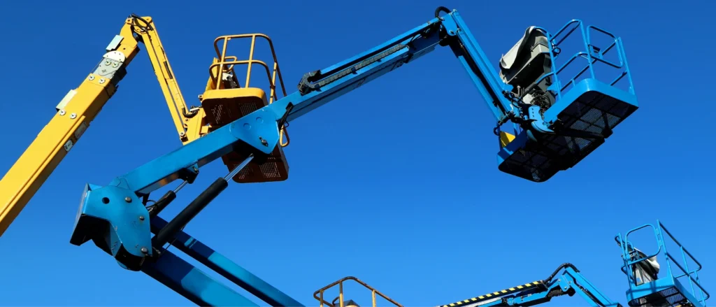
The following uses a set of hypothetical parameters to demonstrate how to determine whether a hydraulic cylinder has ‘sufficient thrust but insufficient buckling margin for the piston rod’.
① Define Pressure, Bore, Rod Diameter, Stroke, and Mounting
Assume you need a hydraulic cylinder to slowly push a load with external guidance, requiring a thrust of 45 kN. The initially selected cylinder has a bore diameter of 63 mm, a solid piston rod diameter of 40 mm, and a stroke of 500 mm. The maximum pressure in the non-rod chamber is calculated at 16 MPa; return line back pressure, friction and inertia are temporarily neglected, and it is assumed that there are no additional pressure peaks or lateral impacts.
The mounting utilises pin connections at the cylinder end and rod end; the centre-to-centre distance between the two pins is 1,000 mm when retracted and 1,500 mm when fully extended. For the purposes of this demonstration, the compressed component is simplified to a uniform circular rod 1,500 mm long with a cross-section identical to that of the piston rod, with both ends treated as ideally hinged; therefore, the effective length coefficient K = 1 and the effective buckling length L_e = 1,500 mm.
This equivalent circular rod is the simplification explicitly adopted in this example; it does not imply that the actual hydraulic cylinder consists entirely of a single circular rod. Actual calculations may also need to take into account cylinder barrel stiffness, internal supports, connection clearances and the direction of installation. The manufacturer’s verification methods will distinguish between specific installation and guidance conditions.
The modulus of elasticity of the material is taken as 210,000 N/mm², representing the material’s ability to resist elastic deformation, and it is assumed that this example satisfies the conditions for elastic buckling. The buckling safety factor is provisionally set at 3; this is for demonstration purposes only and is not a universally recommended value for all hydraulic cylinders.
② Calculate Maximum Cylinder Push Force
First, calculate the piston area, then calculate the theoretical thrust at maximum pressure:
Piston area A = π × cylinder diameter² ÷ 4
A = 3.1416 × 63 × 63 ÷ 4 ≈ 3,117.2 mm²
Maximum theoretical thrust F = pressure × piston area
F = 16 × 3,117.2 ≈ 49,875 N ≈ 49.9 kN
As 1 MPa = 1 N/mm², you may use the units given above directly in your calculations. Assuming no losses, 49.9 kN exceeds the required 45 kN, so the theoretical thrust meets the requirement. However, when selecting the actual component, back pressure and friction losses must still be verified; this theoretical margin cannot be treated in its entirety as available thrust.
The subsequent buckling screening will use 49.9 kN, rather than just the 45 kN required for normal operation. The reason for this is that, should the load become jammed, the piston rod may be subjected to a compressive load approaching this maximum thrust provided the pressure can rise to the 16 MPa specified in this example.
③ Estimate Critical Buckling Load
For the ideal elastic compression member described above, first calculate the section modulus I, which is the geometric parameter representing the section’s resistance to bending, and then substitute this into Euler’s formula:
1. Calculate the section modulus
Section modulus I = π × member diameter⁴ ÷ 64
I = 3.1416 × 40 × 40 × 40 × 40 ÷ 64 ≈ 125,664 mm⁴
2. Calculate the Theoretical Critical Buckling Load
Theoretical critical buckling load = π² × modulus of elasticity × moment of inertia ÷ effective buckling length²
Substituting the data:
Theoretical critical buckling load = 3.1416 × 3.1416 × 210,000 × 125,664 ÷ (1,500 × 1,500) ≈ 115,800 N ≈ 115.8 kN
The theoretical critical buckling load is the load at which the model begins to lose stability. Euler’s formula applies to centrally compressed, slender columns that remain within the elastic range at the point of buckling. This result cannot be directly applied to significantly eccentric, inelastic deformations or complex composite structures.
3. Calculating the preliminary allowable load
Based on the safety factor of 3 assumed in this example:
Allowable load = Theoretical critical buckling load ÷ Safety factor
Allowable load = 115.8 ÷ 3 ≈ 38.6 kN
Therefore, you should compare the maximum thrust of 49.9 kN with the allowable load of 38.6 kN, rather than with the theoretical critical buckling load of 115.8 kN. As 49.9 kN is greater than 38.6 kN, this design does not pass the preliminary screening in this example. The fact that the theoretical buckling point has not yet been reached does not imply that the required safety margin has been achieved.
④ Identify the Governing Limit and Required Design Change
The theoretical hydraulic thrust in this example is 49.9 kN, whilst the permissible compressive load derived from the assumed model and safety factor is only 38.6 kN. In both these checks, the limiting factor for the current design is the buckling resistance: it is lower than both the maximum thrust that the system may exert and the required 45 kN. Consequently, the 40 mm rod diameter design has not passed this preliminary screening.
If the cylinder bore, pressure and calculated length are retained, one could attempt to increase the rod diameter to 45 mm. With all other model conditions remaining unchanged, recalculation yields a theoretical critical buckling load of approximately 185.4 kN; divided by a safety factor of 3, the permissible load is approximately 61.8 kN. As 61.8 kN is greater than the maximum thrust of 49.9 kN, the 45 mm rod diameter has passed the simplified buckling screening for this example and may be considered a candidate for detailed verification in the next stage.
Another approach would be to reduce the pressure. However, if the 40 mm rod diameter is retained, the pressure would need to be limited to approximately 12.4 MPa to ensure the theoretical thrust does not exceed 38.6 kN. In this case, the thrust would again be insufficient to meet the 45 kN operational requirement; therefore, simply reducing the pressure cannot resolve the issue in this example.
You may use this information to make specific requirements to the supplier: Verify the permissible compressive load under actual installation conditions, based on a cylinder bore of 63 mm, a candidate rod diameter of 45 mm, a stroke of 500 mm, a fully extended centre-to-centre distance of 1,500 mm and a maximum pressure of 16 MPa. At the same time, confirm whether the manufacturer’s charts include a safety factor. If the results of the detailed verification differ from the preliminary screening, the model and length definitions should be checked first, rather than directly adopting the higher load-bearing values.
How Can You Increase Allowable Column Load?
The permissible column load of a hydraulic cylinder can primarily be increased by increasing the piston rod diameter, shortening the effective buckling length, and improving the mounting support conditions. The permissible column load refers to the load that a compressed structure can stably withstand under specified operating conditions and with a safety margin. When selecting an improvement scheme, you should first determine whether the limitation stems from an insufficient rod diameter, an excessively long compressed length, or eccentric mounting.
Reducing pressure or minimising impact can also improve the safety margin; however, these measures reduce the actual compressive load without directly enhancing the piston rod’s inherent buckling resistance. This distinction is important because, following a pressure reduction, you must also verify that the thrust remains sufficient to perform the required task.
Increase Rod Diameter
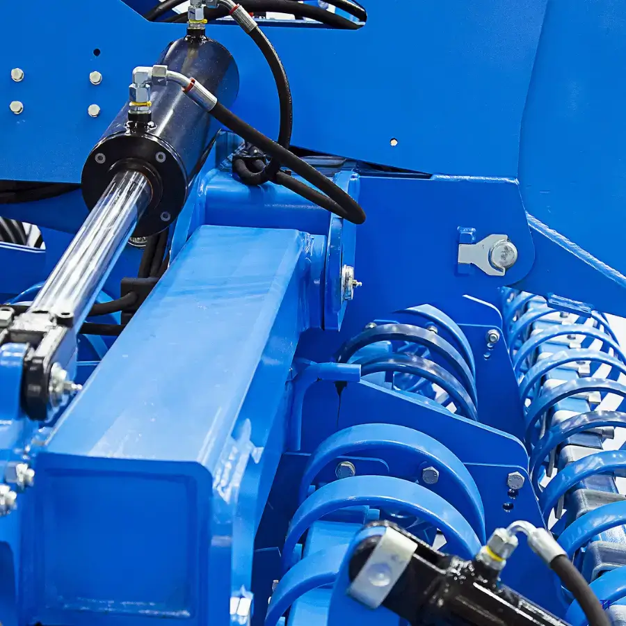
Increasing the rod diameter is usually the most direct way to improve the buckling resistance of a slender piston rod. When the material, effective length and mounting conditions are the same, and the Euler elastic buckling model applies, the theoretical critical buckling load of a solid circular rod is proportional to the fourth power of the rod diameter. Therefore, even a small increase in rod diameter can significantly improve the buckling margin.
For example, whilst the aforementioned conditions remain unchanged, increasing the rod diameter from 40 mm to 45 mm results in the theoretical critical buckling load becoming approximately 1.60 times the original value, calculated as ‘(45 ÷ 40)⁴’. This is merely a ratio derived from an idealised model and should not be interpreted directly as a 60 per cent increase in the rated load of the entire hydraulic cylinder.
You should ask the manufacturer to re-engineer the rod diameter, cylinder head guidance and sealing configuration, rather than simply replacing the rod with a thicker one. For standard double-acting hydraulic cylinders with a single piston rod, increasing the rod diameter will also reduce the effective cross-sectional area of the rod chamber, thereby lowering the theoretical return force at the same pressure. Consequently, if your equipment requires both high thrust and significant return force, both operating conditions must be verified.
Reduce Unsupported Length or Stroke
Shortening the length under compression that lacks lateral support can improve structural stability. For the same ideal elastic compression member, the theoretical critical buckling load is inversely proportional to the square of the effective length. If the effective length is reduced by 20 per cent, with all other conditions remaining constant, the theoretical critical load increases by approximately 56 per cent; the calculation relationship is ‘1 ÷ 0.8²’.
In practical design, you should first check whether there are any unnecessary end extensions on the rod, or whether the position of the hydraulic cylinder relative to the load can be adjusted so that the high thrust occurs at a shorter extension. For example, if the press-fitting operation requires only a small final segment of displacement, you can assess whether to adjust the fixture position to reduce the extension length of the piston rod whilst the press-fitting force is being applied.
Shortening the stroke will only yield corresponding improvements if the actual compressed length is reduced accordingly. If you shorten the hydraulic cylinder stroke but compensate for the installation distance with a long coupling, the expected benefits may be offset. Following any modifications, the effective length must be redetermined based on the new installation drawing; one must not simply compare the stroke specified in the product data.
Improve Mounting and Load Alignment
Improving the mounting can increase the safety margin in two ways: firstly, by providing more reliable lateral or rotational constraints; and secondly, by reducing the additional bending caused by eccentricity. You need to check whether the frame, mounting brackets, pins and load guides deform noticeably under load, rather than simply confirming that the bolts have been tightened.
If the load moves in a straight line, ensure that the guide rail is correctly aligned with the hydraulic cylinder axis; if the load moves along an arc, the mounting and rod-end connections must be designed to allow for mechanical oscillation. Parker’s installation documentation clearly distinguishes between linear force transmission and oscillating installations, and requires that the load be effectively guided to prevent lateral forces from being transmitted to the internal supports of the hydraulic cylinder.
You must not forcibly lock a connection that is intended to swing simply to achieve a smaller effective length factor in calculations. Doing so may introduce new bending loads. A practical approach is: to check the axis alignment, connection rotation angle and bracket deflection on the full-stroke installation drawing, and then have the manufacturer confirm the permissible end constraints.
Reducing System Pressure or Peak Load
If the load-carrying capacity of the existing hydraulic cylinder cannot be increased, one may consider reducing the maximum operating pressure so that the compressive force potentially generated by the system falls within the permissible range. Provided the cylinder bore remains unchanged and back pressure is negligible, a 10 per cent reduction in pressure will result in a theoretical reduction in thrust of approximately 10 per cent. However, this approach is not suitable if normal operation is already approaching the thrust limit.
Continuing with the previous educational example, the theoretical thrust for a 63 mm cylinder bore at 16 MPa is approximately 49.9 kN. If the permissible compressive load is only 38.6 kN, the corresponding upper pressure limit is approximately 12.4 MPa; however, when the equipment requires 45 kN, reducing the pressure will not simultaneously meet the operational requirements, and you will still need to adjust the structural or mechanical design.
For peak loads caused by sudden contact with the workpiece, emergency stops or jamming, measures such as reducing the contact speed, extending the deceleration process or implementing appropriate cushioning measures can be evaluated. Reducing the speed primarily helps to minimise dynamic impact and does not automatically reduce the static thrust that continues to build up after jamming. Similarly, the nominal setting of the relief valve must not be taken directly as the absolute pressure limit for all transient conditions.
Use Stop Tubes, Intermediate Support, or a Different Cylinder Arrangement
A stop tube is a spacer used inside the cylinder to maintain the distance between the piston and the rod guide support. It primarily reduces the support load when a long-stroke hydraulic cylinder is extended by increasing the support spacing. A stop tube does not involve increasing the diameter of the piston rod, nor is it equivalent to adding an external support point in the middle of the exposed rod section. Parker describes the function of a stop tube as increasing the distance between the piston support and the rod support to reduce the support load.
If the working stroke is to remain unchanged, the use of a stop tube may require an increase in the overall length of the hydraulic cylinder; therefore, the installation dimensions and buckling resistance must be re-verified. Peninsular’s selection method also requires the rod diameter to be re-selected based on the adjusted length after the stop tube has been fitted. One must not assume that ‘adding a stop tube eliminates the need for a thicker piston rod’.
An intermediate support can only serve as an effective constraint if it possesses sufficient stiffness and load-bearing capacity, and is capable of restricting lateral displacement in the required direction. For reciprocating piston rods, the support must also allow for normal axial movement and prevent damage to the rod surface. In practical projects, the manufacturer should be tasked with designing a dedicated support or guide structure, rather than simply shortening the calculated length by retrofitting a sleeve.
If installation space does not permit increasing the diameter or shortening the compression rod, one may consider modifying the mechanism so that the primary working force is transmitted via the piston rod under tension, thereby avoiding buckling issues in the compression rod under these operating conditions. However, the retracting force of a standard single-piston hydraulic cylinder is typically lower than the extending thrust at the same pressure, so this must be re-verified. If multiple cylinders are used to share the load, one must not simply assume that the force is distributed evenly across each cylinder; synchronisation errors and off-centre loading must also be taken into account.
What Should Engineers Verify Before Ordering?
Before placing an order, you should confirm that the hydraulic cylinder has a sufficient allowable compression load under the actual installation configuration, at the maximum loaded extension position, and throughout a complete working cycle. It is not sufficient to merely verify the cylinder bore, stroke and rated pressure. You must also ask the supplier to specify the conditions under which the load-bearing data applies, and include the installation dimensions, load requirements and acceptance procedures in the technical confirmation document.
1. Manufacturer’s Column-Load Chart and Safety Factor
Firstly, request the column-load chart, piston rod selection chart or calculation report for the relevant product series from the supplier. Confirm that the rod diameter, calculated length, cylinder mounting method and rod end connections specified therein correspond to the configuration you are actually ordering. Standard product charts may not necessarily apply to extended rods, special fittings or modified mounting configurations.
You must clarify whether the chart provides theoretical critical loads or permissible loads that already incorporate a safety factor. If they are permissible loads, you should confirm the safety factor and the applicable operating conditions; if they are critical loads, they cannot be directly taken as the upper limit for operation. The buckling assessment method in ISO/TS 13725:2021 also requires the engineer to determine the safety factor and report it alongside the calculation results.
In practice, you may request that the supplier specify in the confirmation document: ‘Under the attached installation drawings and specified load conditions, what is the permissible compressive load for this configuration, and what calculation method and safety factor were used?’ Compared to a simple statement such as ‘this model is suitable for use’, such confirmation makes it easier for you to verify the details and helps avoid the misuse of previous conclusions when dimensions are subsequently modified.
2. Maximum Extension Under Load
You need to confirm the maximum extension position when subjected to a compressive load, and the maximum load corresponding to that position. Total stroke merely refers to the distance the hydraulic cylinder can travel and does not, on its own, indicate the most hazardous load condition.
For example, suppose the hydraulic cylinder has a total stroke of 500 mm, and under normal operating conditions, significant thrust is only applied when the cylinder is extended by 300 mm. If the equipment could still come into contact with an obstacle whilst fully extended to 500 mm and continue to build up pressure, the verification must not be based solely on the 300 mm position. Only when the loaded position and load are reliably restricted in the design can a smaller working range be adopted on this basis.
You may provide a ‘chart showing the correspondence between extension positions and compressive loads’, marking at least the maximum load-bearing extension position, the position of maximum compressive force and any potential jamming positions. Request that the supplier compare these operating conditions and identify the one with the smallest safety margin. If the stroke is subsequently increased, rod end extensions are fitted or the fixture position is altered, the load-bearing capacity must be re-verified.
3. Mounting Centres, Side-Load Control, and Duty Cycle
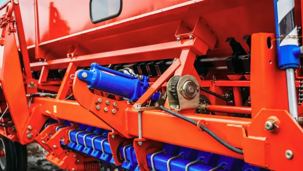
Mounting centre distances refer to the distance between specified mounting reference points, such as the distance between the centres of the two end pins. Before placing an order, you should verify the centre distances in both the retracted and extended positions, the pin dimensions, the rod end fittings and the required swing angle to avoid substitution issues where ‘the stroke is the same, but the load conditions differ once installed’.
Side-load control must also be applied to specific components. You should clarify which set of guide rails, guide columns or mechanical pivot points bears the lateral forces and tilting moments of the load, and ensure that their direction of movement is correctly aligned with the hydraulic cylinder. The internal guidance of standard hydraulic cylinders cannot be assumed to replace external load guidance; manufacturers’ installation documentation also requires effective load guidance to minimise the lateral forces transmitted to the rod guides and piston supports.
The duty cycle describes how the hydraulic cylinder operates repeatedly, including operating frequency, daily operating hours, movement speed, alternation between compression and tension, and impact conditions. For example, ‘6 reciprocating cycles per minute, 16 hours of operation per day, with emergency stops at the end of the stroke’ is more helpful to suppliers in making judgements than simply stating ‘continuous use’. The figures provided here are merely illustrative examples and do not represent recommended operating conditions.
Passing the static buckling test does not imply that the fatigue life under repeated operation has been verified. Fatigue is the process by which a material gradually deteriorates under repeated loading. You should request that the supplier also verify the cyclic load requirements for rod-end threads, pins and mounting components; Bosch Rexroth’s technical specifications also state that the permissible load on connecting components may be reduced due to alternating loads.
4. Proof Pressure and Application-Specific Standards
Proof pressure is the test pressure applied during acceptance testing in accordance with prescribed procedures; it cannot be directly regarded as the permissible pressure for long-term operation. Prior to placing an order, you should confirm the test basis, pressure, pressure holding time, test location and pass/fail criteria, and agree whether test records traceable to the delivered hydraulic cylinder will be provided.
Passing a proof pressure test does not prove that the hydraulic cylinder will not buckle when fully extended and subjected to compressive loads. The support configuration and force paths during a proof pressure test may differ from those under actual loading conditions; therefore, buckling resistance must still be confirmed through applicable calculations, charts or specific verification, and cannot be substituted by a proof pressure test report alone.
Standards should also be distinguished according to their intended use. ISO 10100:2020 specifies acceptance and functional tests for hydraulic cylinders; ISO 4413:2010 covers general rules and safety requirements for mechanical hydraulic systems and their components. As the focus of these two standards differs, the scope of acceptance cannot be determined solely on the basis of the general statement that they ‘comply with ISO standards’.
If ISO/TS 13725:2021 is used to assess buckling, it must also be confirmed that the product falls within its scope of application. For example, this method is not designed for thin-walled hydraulic cylinders, double-rod cylinders or piston cylinders, and cannot be directly applied to all configurations. For lifting equipment, presses or other equipment with specific requirements, you should also clarify the applicable equipment standards, versions and acceptance criteria for the project, and confirm these with the supplier before placing an order.
Frequently Asked Questions About Hydraulic Cylinder Column Load
Is Column Load the Same as Cylinder Push Force?
Not exactly. Column load describes the actual axial compressive force borne by the piston rod, whilst hydraulic thrust describes the propulsive force generated by the hydraulic pressure. When pushing a load slowly and steadily, and disregarding friction and inertia, the two may be approximately equal. However, the maximum thrust specified for a product does not mean that the piston rod is constantly subjected to that level of pressure.
When verifying specifications, you should consider the maximum compressive load that the system may exert, including situations where pressure rises following jamming. You should then compare this with the permissible column load under actual installation conditions; it is not sufficient merely to confirm that the ‘hydraulic thrust is adequate’. When selecting a model based on normal load pressure, you must also ensure that the actual pressure does not exceed the calculated conditions.
Does a Larger Bore Prevent Rod Buckling?
Increasing the cylinder bore alone cannot prevent piston rod buckling, i.e. instability and bending under compression. A larger cylinder bore increases the theoretical thrust at the same pressure; however, if the rod diameter and support conditions remain unchanged, the greater compressive force may actually reduce the safety margin against buckling.
For example, when back pressure and friction are ignored, a 10 per cent increase in bore diameter results in an approximate 21 per cent increase in theoretical thrust at the same pressure, as the piston area is proportional to the square of the bore diameter. This is a geometric calculation, not product test data. When replacing a hydraulic cylinder with a larger bore, you should simultaneously verify the rod diameter, maximum loaded extension length and mounting configuration, rather than simply comparing thrust figures.
Why Is a Cylinder Strongest When Retracted?
If you are referring to the ability to resist compressive buckling, standard hydraulic cylinders generally perform better when retracted or at shorter extension lengths. At these points, the effective length of the compressed component is typically shorter, and the internal support conditions are often more favourable, making lateral bending less likely to occur. However, the actual load-bearing capacity still depends on the mounting and guidance conditions, so no generalisation can be made.
This does not imply that the retracted position can generate greater hydraulic thrust. For standard single-stage hydraulic cylinders, under identical conditions of pressure, effective area and back pressure, the theoretical thrust in the same direction of movement will not increase simply because the extension length changes. You should focus on checking the maximum loaded extension position and verify whether greater compressive loads occur at other positions.
Can a Stop Tube Increase Column Load Capacity?
It may be helpful, but there is no guarantee that fitting a stop tube will increase the permissible column load. A stop tube is a spacer used inside the cylinder to maintain the distance between the piston and the rod guide bearing; its primary function is to improve support conditions during extension and reduce the load on the support. It neither increases the rod diameter nor replaces external load guidance.
If the working stroke remains unchanged, the addition of a stop tube may increase the overall length of the hydraulic cylinder, affecting buckling calculations. You should therefore ask the supplier to re-verify the permissible compressive load based on the modified installation length, support structure and rod diameter. The manufacturer’s selection method will also re-examine the rod diameter once the stop tube is incorporated; the stop tube must not be regarded as a substitute for buckling verification.
Choosing a Trusted Hydraulic Cylinder Manufacturer
From standard hydraulic cylinders to custom solutions, we help you improve equipment performance, delivery reliability, and batch consistency
Explore Rivmate Cases

Hey There, I'm Melody!
We are a hydraulic cylinder manufacturer. For over 20 years, we have focused on producing reliable hydraulic cylinders. Need a hydraulic cylinder solution? Feel free to contact us.