Home / Linear Actuator vs Hydraulic Cylinder: Selection Guide
Linear Actuator vs Hydraulic Cylinder: Selection Guide
- Author: GY Hydraulic
- 20+ Years of Manufacturing
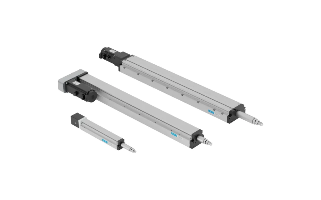
A hydraulic cylinder is, in itself, a type of linear actuator. When selecting equipment and searching for linear actuator vs hydraulic cylinder, people are usually seeking to compare electric lead screw actuators with hydraulic cylinders: the former uses a motor to drive a lead screw to produce linear motion, whilst the latter uses hydraulic oil pressure to push a piston. You need to select a system capable of pushing, pulling, stopping and holding as required; simply comparing the parameters of the two output rods can easily overlook the impact of the power unit, drive unit and safety devices.
If the equipment already has an available hydraulic power source, and the operating space is confined whilst requiring significant axial thrust, you may wish to evaluate the hydraulic solution first; if frequent switching between positions and speed profiles is required, or if you wish to minimise the number of hydraulic hoses at the operating point, you may wish to evaluate the electric lead screw solution first. Finally, compare the two within the same real-world motion cycle: can the system reach the most demanding positions, can it complete the cycle as required, and what happens to the load in the event of a power failure?
Table of Contents
Hydraulic Cylinders Are Linear Actuators: Defining the Comparison
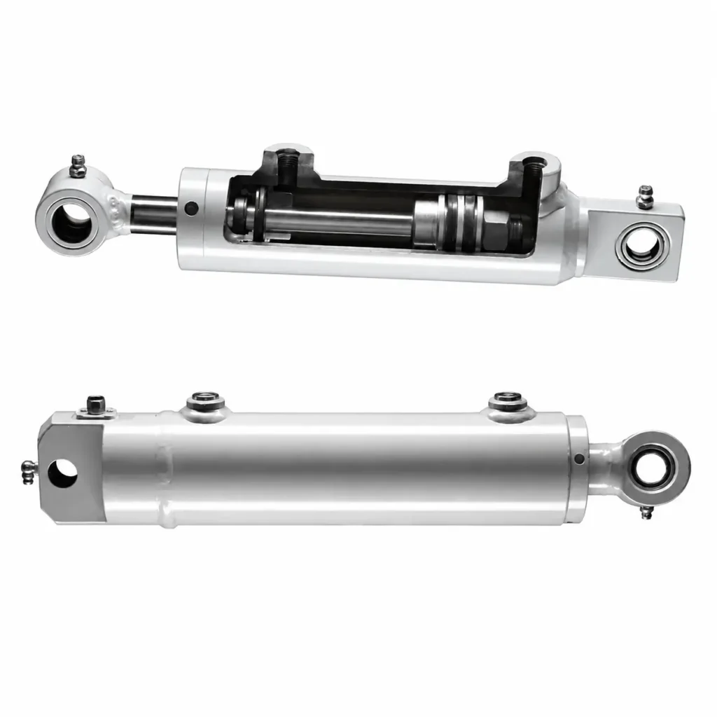
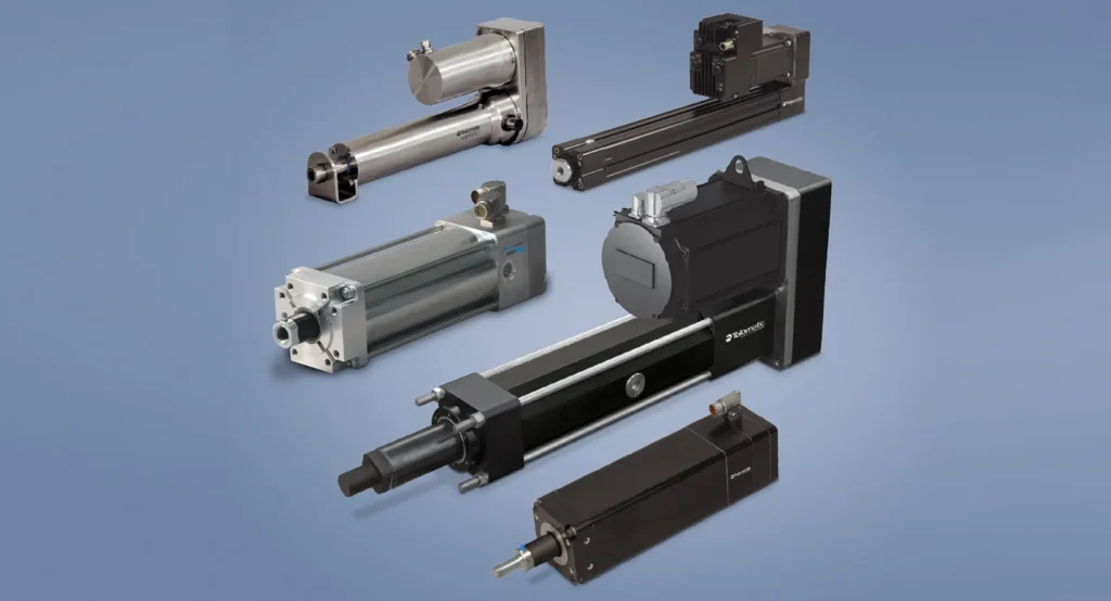
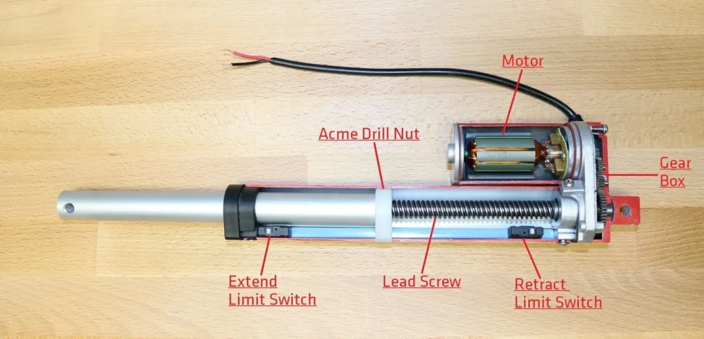
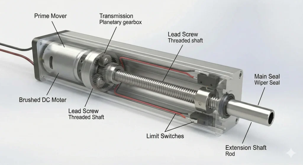
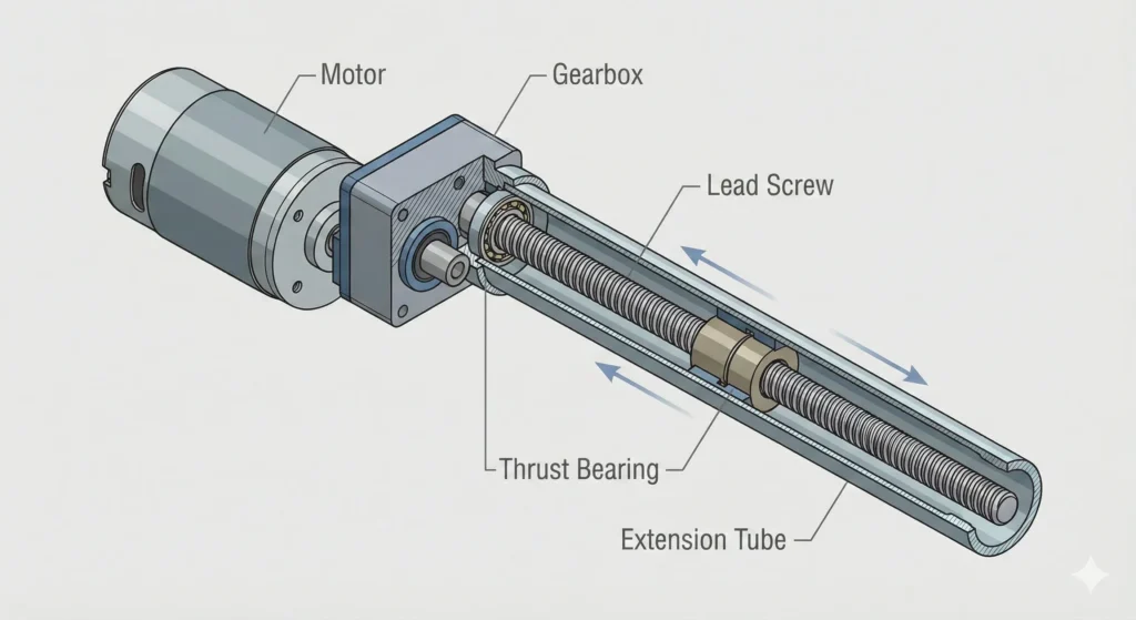
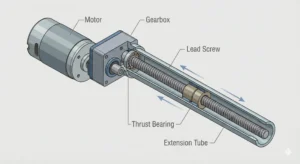
A linear actuator is a component that converts input energy into linear motion; hydraulic cylinders, electric actuators, and pneumatic cylinders all fall into this category. This article compares only the electric lead screw actuators and hydraulic cylinder systems commonly found in industrial equipment. A lead screw works in conjunction with a nut to convert rotational motion into linear motion; a hydraulic cylinder, on the other hand, uses hydraulic pressure to drive a piston inside the cylinder, which then transmits force to the load via the piston rod. Double-acting hydraulic cylinders, which can actively exert force in both directions, require oil to be supplied to different chambers depending on the direction of operation.
Below are schematic diagrams illustrating the functions of the two systems; the arrows indicate how power is transmitted to the load. Actual wiring, hydraulic return lines, and safety circuits should be based on the equipment drawings.
Electric Screw Actuator System
- Power Supply & Motion Commands
- Motor Drive & Motor
- Screw & Nut
- Linear Push/Pull
Hydraulic Cylinder System
- Power Source
- Hydraulic Pump & Reservoir
- Control Valves & Hydraulic Lines
- Hydraulic Cylinder
- Linear Push/Pull
A drive is an electronic device that regulates the motor’s current, speed, and other operations; a hydraulic power unit (commonly called a pump station) supplies oil to the hydraulic system via a pump, reservoir, and related components. For example, when comparing a new workbench, on the electric side, you must factor in the drive unit and power supply, while on the hydraulic side, you must factor in the pump station, valves, and piping. If the workshop already has a shared pump station, you must also verify the actual pressure and flow rate the workbench can achieve when other equipment is operating simultaneously. Only then can you ensure that the comparison is based on identical work tasks.
Electric Screw Actuators vs. Hydraulic Cylinders: Selection Matrix
First, use this table to eliminate options that do not meet the operating conditions, then perform calculations on the remaining models. The “priority evaluation” mentioned in the table serves as the starting point for selection; actual results depend on component configuration and operating conditions.
| Comparison Criteria | Electric Screw Actuator | Hydraulic Cylinder System | What You Need to Confirm |
|---|---|---|---|
| Thrust/Pull Force and Speed | Suitable for setting force and speed according to different process steps; for high loads, check how much continuous output the motor and lead screw can provide at the target speed. | Worth evaluating when working space is limited but a large axial force is required; actual force and speed depend on the pressure in both chambers, their cross-sectional areas, and the oil supply and return capacity. | The force and speed required at any given moment, as well as how long they must be sustained. |
| Position and Force Control | Motorized systems with feedback facilitate switching between multiple positions and speeds; the force applied to the workpiece must still be verified based on the actual detection method. | Standard valve-controlled systems are suitable for many reciprocating motions; to precisely adjust intermediate positions or forces, consider feedback control with sensors. | Where measurements are taken, what deviation is allowed, and how much the load varies. |
| Installation Space | The work area must accommodate the motor or drive components; do not overlook cables and the drive cabinet. | The cylinder can be located at the work area, while the pump station can be placed remotely or shared; however, valves and hoses must still be routed. | Retracted and extended dimensions, space for the cabinet or pump station, and access for maintenance. |
| Operating Environment | Suitable for workstations where hydraulic lines need to be minimized; dust, flushing, and high temperatures still require verification of motor, fitting, and seal configurations. | Select appropriate designs for dust, temperature, and shock; manage fluid contamination, leaks, and line protection. | Actual exposure conditions, as well as permissible levels of contamination and cleaning methods. |
| Maintenance | Focus on inspecting lead screw lubrication, bearings, brakes, cables, and drives; perform maintenance according to model specifications. | Focus on inspecting hydraulic fluid, filter elements, hoses, seals, and exposed rod surfaces; perform maintenance according to system requirements. | What can be repaired on-site, how long it takes for spare parts to arrive, and how long downtime will last. |
| Acquisition and Operating Costs | For new equipment, if a dedicated pump station can be eliminated, compare the total system cost; do not base calculations solely on the electric cylinder’s quoted price or rated power. | When existing hydraulic infrastructure can be reused, compare based on incremental costs; energy consumption and maintenance allocated to that operation must still be factored in. | Total cost under the same production volume, operating conditions, and service life. |
For example, for packaging lines that frequently switch workpiece sizes and require multiple intermediate positions, electric lead screws should be prioritized in the cost analysis. For heavy-duty clamping fixtures in existing hydraulic systems that only require fixed extension and retraction movements, first verify whether the original oil supply can meet the demands of the most strenuous process step. In both cases, clearly define the acceptance criteria upfront to avoid comparing a basic model with a high-specification system of a different category.
Sizing for Force, Speed, Stroke, and Duty Cycle
① Put Force and Speed on the Same Timeline
Break down the motion into approach, work, hold, return, and wait phases. Stroke refers to the distance the output end travels; the duty cycle describes how the work, hold, and rest phases are sequenced. When selecting a cylinder, you must know not only the peak force but also how long the force is applied, at what position it occurs, and what the speed is at that moment. For lifting mechanisms, the actual force borne by the cylinder’s axis must also be calculated based on the rotation axis and installation position, as the same load may require different thrusts depending on its orientation.
Below is a set of hypothetical horizontal press-fit operating conditions that can serve as an example for filling out the requirements table. The push and pull forces represent the assumed requirements for the actuator during this process step; acceleration and deceleration during start-up and stop are not listed separately for now. The force required during the hold phase is a process requirement; verification is still needed to determine whether it can be maintained during the hold period.
| Process Step | Displacement | Axial Force Requirement | Target Speed | Theoretical Process Time |
|---|---|---|---|---|
| Approach Workpiece | Extend 150 mm | Thrust 3 kN | 100 mm/s | 1.5 s |
| Press-Fit | Extend another 50 mm | Thrust 12 kN | 25 mm/s | 2.0 s |
| Hold | Stop at working position | Maintain 12 kN | 0 | 1.0 s |
| Return | Retract 200 mm | Tension 2 kN | 80 mm/s | 2.5 s |
| Wait | No movement | Determined by equipment status | 0 | 3.0 s |
In this example, the total stroke is 200 mm, and one cycle lasts 10 s, with 6 s spent in motion; the motion time accounts for 60% of the cycle. This does not mean it can be directly compared to the “60% duty cycle” listed in electric actuator catalogs: if the motor continues to output force during the hold phase, it may continue to generate heat; specific assessments must be made based on the time window, load, and temperature conditions specified for each model. You can substitute the displacement, force, speed, and time values in the table with measured or design values, then add the acceleration and deceleration requirements, cycles per hour, and continuous operating time.
② Check Both Hydraulic Chambers
For a standard single-rod, double-acting hydraulic cylinder, the cylinder bore refers to the inner diameter of the cylinder barrel, which determines the total effective area of the rodless chamber; the rod chamber has part of its area occupied by the piston rod. The theoretical net fluid pressure during extension is calculated by subtracting the opposing force on the opposite side from the “pressure × area” on the inlet side, and then accounting for friction. Return line back pressure is the pressure generated by resistance encountered when fluid is discharged; the reading at the pump outlet may not necessarily equal the pressure at the cylinder port.
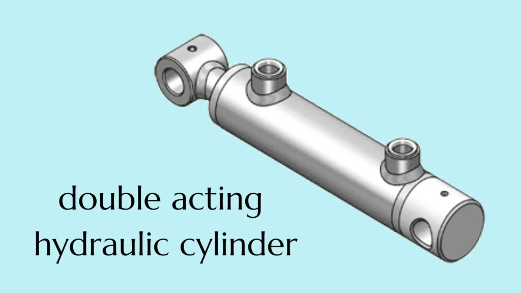
Using the table above as an example: Suppose a candidate cylinder has a bore diameter of 50 mm and a rod diameter of 30 mm, with pressures of 8 MPa in the rodless chamber and 1 MPa in the rod chamber during press-fitting. The total area is approximately 1,963.5 mm², and the effective area on the rod side is approximately 1,256.6 mm². Since 1 MPa = 1 N/mm², after accounting for back pressure, the theoretical net fluid pressure is approximately 14.45 kN, not yet accounting for friction. This is merely a preliminary result for comparison with the 12 kN requirement and does not prove that the assembly, rod, or entire machine meets the specifications.
Flow rate is the volume of oil delivered or discharged per unit of time. When leaks and oil compressibility are neglected, the flow rate is approximately equal to the effective area multiplied by the velocity. For the same candidate cylinder approaching at 100 mm/s, the theoretical inlet flow rate is approximately 11.78 L/min; when the press-fit speed is 25 mm/s, it is approximately 2.95 L/min. When retracting at 80 mm/s, the oil inflow is approximately 6.03 L/min, while the oil outflow on the other side is approximately 9.42 L/min. Therefore, in addition to verifying the pump’s oil supply capacity, it is necessary to verify whether the valves and return lines can handle the actual oil outflow and to separately confirm the available pulling force during retraction.
③ Check Electric Thrust at the Required Speed
For electric drive solutions, the force-speed relationship should be verified against the same operation schedule: how long the peak thrust specified by the supplier can be sustained, how much force remains available at the target speed, and whether the motor and driver will overheat after repeated cycles. For lead screws, verify the stroke, permissible rotational speed, whether they will bend or become unstable under compression, and their service life after repeated loading. The maximum thrust and maximum speed listed separately in the catalog may not necessarily be achievable simultaneously.
Using the table above for comparison: the ideal mechanical power under an approaching load is 3 kN × 0.1 m/s = 0.30 kW, and during press-fitting it is 12 kN × 0.025 m/s, which is also 0.30 kW. Multiplying the maximum force and maximum speed for different operational steps yields 1.20 kW; however, this does not mean that any single step in the table requires this mechanical power. Conversely, 0.30 kW is not the selection value for a motor or pump station: acceleration and deceleration, transmission and hydraulic losses, as well as the energy required to maintain output during dwell periods, must also be considered.
Positioning Accuracy, Repeatability, and Force Control
Positioning accuracy answers the question, “How far is the actual stopping point from the target?” Repeatability answers the question, “When the same motion is repeated, how much do the stopping points differ from one another?” For example, if a device consistently stops approximately 0.2 mm to the right of the target and the stopping points are highly concentrated, this indicates that it may have good repeatability but still exhibits a fixed deviation. This figure is provided solely to illustrate the concept. When writing acceptance criteria, you should specify whether measurements are taken at the actuator rod end or the workpiece, whether the system is under load, from which side the approach is made, and ensure measurements are taken under comparable temperature and load conditions.
Electric systems with position feedback typically facilitate the setting of multiple positions and acceleration/deceleration profiles; feedback occurs when a sensor sends the actual status back to the control system, allowing it to correct the motion based on the deviation. However, an encoder on a motor only directly measures the motor’s rotation; lead screw backlash, mechanical deformation, or loose connections can still affect the workpiece’s position. Conventional hydraulic cylinders use on/off directional control valves to switch the flow of hydraulic fluid, enabling reciprocating motion between the two ends; to precisely control intermediate positions, a servo-hydraulic system equipped with a displacement sensor and a continuously adjustable valve can be used to correct position and speed through feedback. A standard hydraulic circuit without feedback cannot be taken as representative of the full capabilities of hydraulic systems.
Force control is another matter entirely. Motor current can be used to estimate output force, and hydraulic force can be estimated based on pressure in the two chambers and effective area; however, friction, transmission losses, and forces acting on the mechanism will all affect the results. For example, in a press-fitting process, to determine whether a part is correctly positioned, one might consider installing a force sensor along the force path and recording the force and displacement at the workpiece location, rather than directly treating the drive current or a single pressure reading as the force acting on the workpiece.
Installation Space: Actuators, Power Units, Drives, and Connections
First, determine whether the operating point can accommodate the installation; then, plan the layout of the entire system. Using a single installation reference, mark the retracted length, extended length, the positions of the two mounting points, and the range of motion during operation. On the electric side, allow space for the motor, any necessary reduction gear, cable bends, and the drive cabinet; on the hydraulic side, verify the orientation of the oil ports, fittings, minimum hose bend requirements, and the locations of the valve block and pump station. Space should be reserved on both sides for disassembly and assembly to prevent situations where the layout fits on the plan but fasteners cannot be reached in practice.

For example, a hydraulic power unit can be positioned on the outside of the equipment, but the hydraulic hoses must still be able to follow the mechanism’s movement; when the motor and lead screw are aligned along the same axis, the motor may extend backward and occupy additional space, so if a side-mounted motor is used instead, the lateral clearance must also be verified. You can overlay the dimensional drawings of candidate products onto the same equipment drawing to first identify any motion interference, then verify how hydraulic hoses or cables will pass through, and how the assembly can be removed for maintenance.
Operating Environment, Reliability, and Maintenance
Define “harsh environments” as verifiable conditions: minimum startup temperature, operating temperature, dust type, flushing method, corrosive media, shock loads, and continuous operating time. The fact that electric actuators do not require supply and return oil lines at the operating point does not mean they are maintenance-free or require no lubrication whatsoever; similarly, hydraulic cylinders should not be installed without proper rod protection, clean hydraulic fluid, and proper alignment simply because they are labeled “heavy-duty.” In particular, lateral loads—that is, forces pushing the rod sideways—should be absorbed by appropriate guide structures, unless the actuator is explicitly designed to withstand such loads.
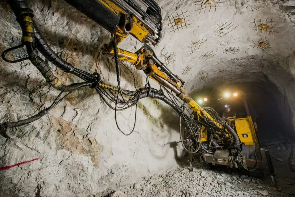
For example, at workstations subject to frequent water flushing, the electric side must verify whether the housing, connectors, and cable entries can withstand the actual flushing conditions; the hydraulic side must verify the dust seals, rod surface corrosion protection, hoses, and the consequences of fluid leaks. For intermittent heavy impacts, the permissible loads for the lead screw, rod, and mounting components must also be verified separately; it cannot be assumed that switching to any other type of drive will eliminate the impact problem. Before purchasing, have both parties clearly document maintenance items, required tools, critical spare parts, and turnaround times, and then assess which solution is more likely to restore production based on on-site maintenance capabilities.
Load Holding, Power Loss, and Safe Stopping
Separate Holding from Stopping
Load holding prevents unintended movement after the mechanism has come to a stop; a safety stop, on the other hand, requires a moving mechanism to decelerate as designed and remain in a safe state after coming to a stop. The ability to hold a static position does not prove the ability to bring a moving load to a stop. Some electric lead screws may be driven in the opposite direction by the load after power is cut off; this is called reverse drive. Standard motor holding brakes are typically used for static holding and cannot be assumed to withstand repeated braking or all emergency stops. Hydraulic holding valves bear the load by restricting fluid flow; the specific failure scenarios they protect against depend on the valve’s function, location, and actual hydraulic circuit.
Review the Failure Conditions as a System
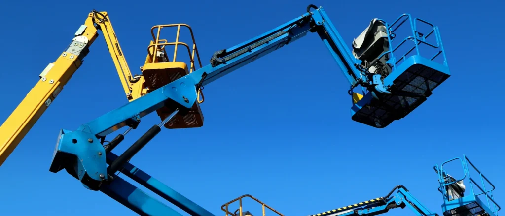
Taking a vertical lifting workstation as an example, before placing an order, you should specify whether the load must be held, what the allowable displacement is, when controlled stopping or lowering is required, and how to resume operation afterward. The table below lists design verification items for the entire machine; it is not intended as a test procedure for manually cutting off hydraulic pressure or power on-site.
| Scenario | Hydraulic System Verification | Electric System Verification |
|---|---|---|
| Normal Stop and Position Holding | Which valve or mechanical device controls the load-bearing fluid, and has the allowable displacement been verified? | What roles do the motor, brake, and mechanical lock each play, and can they maintain the required position? |
| Power Interruption or Critical Component Failure | What fluid pathways exist in the event of pump shutdown, power loss, or load-bearing hose rupture? Are the pipe sections between valves and cylinders within the protected range? | In the event of a power outage, drive failure, or brake failure, will reverse drive occur, and can the residual protection support the load? |
| Emergency Stop During Motion | Actual deceleration and stopping distance, local pressure in the load-bearing oil circuit, and post-stop status | Deceleration capacity required, brake engagement timing, stopping distance, and load-bearing method after stopping |
| Restart and Maintenance | Who assumes responsibility for the load before releasing the hold, and how is the load secured and residual pressure verified during maintenance | Who assumes responsibility for the load before releasing the brake, and how is unintended startup prevented after power is restored |
For example, locating the load-holding valve at a remote pump station does not guarantee protection in the event of a load hose rupture between the valve and the hydraulic cylinder; Nor does installing a standard holding brake on a motor guarantee that the load will remain supported in the event of a nut or drive connection failure. For equipment posing a risk of falling or pinching, the equipment manufacturer must verify the failure response. Before maintenance, establish mechanical supports or interlocks in accordance with equipment procedures, isolate the power source, and verify residual pressure; neither power disconnection nor a pressure gauge reading of zero alone indicates that a gravity-loaded load has been secured.
Total Cost of Ownership: Equipment, Energy, Maintenance, and Downtime
Total Cost of Ownership (TCO) is the cost you incur over the same comparison period to achieve the same output and operational performance. Enter each item on a separate line: Comparison Period ___; Equipment Purchase ___; Installation and Control Integration ___; Energy Consumption During the Period ___; Maintenance and Spare Parts ___; Downtime Losses ___; Total ___. Both scenarios should include the necessary control and safety components. Downtime losses can be estimated by multiplying projected or historical downtime by the attributable hourly loss; avoid double-counting costs already listed under maintenance.
For new construction scenarios, include the actual costs of the required pump station or motor drive, installation, and utility connection. When retrofitting existing equipment, distinguish between costs already incurred and those that are new or avoidable in this project. For example, if a pump station also supplies oil to three other pieces of equipment, replacing one cylinder does not mean the entire cost of the pump station can be counted as a savings under the electric solution; however, if the shared pump station has no spare capacity, the cost of the pump or cooling upgrades required for the new hydraulic workstation should be included in the cost of this solution.
Energy consumption should be compared based on identical operations, output, and operating times. It is best to record electricity consumption for a complete cycle or a representative production period, including standby, hold, and required cooling. Even when the electric system is not moving, it may continue to consume electricity to maintain process force; the energy consumption of a hydraulic pump station during non-operational periods depends on unloading, speed control, and sharing arrangements. In the absence of these conditions, use clear estimation ranges for comparison; do not assume in advance that one side will necessarily save electricity or specify a fixed payback period.
Replacing a Hydraulic Cylinder with an Electric Actuator: Compatibility Checks
1. Measure the Existing Job, Not the Nameplate Maximum
Before replacing the cylinder, determine why the original cylinder was selected: it may have been designed with a margin for shock, startup, or future loads, and the maximum pressure listed on the nameplate is not necessarily reached during every operation. You can record the displacement, actual speed, and load for each stage according to the operating conditions table provided earlier; If calculating push or pull force from hydraulic pressure, use verified pressures at both cylinder ports, effective area, and direction of motion, while accounting for friction and dynamic effects. Pressure and position readings must be taken by qualified personnel at specified measurement points; do not loosen pressurized fittings on your own. When conditions permit, use a suitable force measurement device to verify the force at the workpiece.
2. Check the Interfaces Before Ordering
- Mechanical Interfaces: Compare against the drawings to verify mounting pins and threads, mounting distances at both ends, actual stroke, alignment, and load guidance; confirm that no new interference occurs when the original mechanism swings.
- Space and Access: Verify the layout of the motor, drive, cables, and connectors, and confirm power supply capacity and control cabinet space. Areas where hoses were previously used to provide clearance may not be suitable for direct cable routing.
- Force and Cycle Time: Use actual motion profiles to verify speed under load, thermal load from repeated cycles, shock loads, and allowable stroke; do not assume that identical installation lengths or rated thrusts imply equivalent performance.
- Control and Load-Bearing: Verify the original controller’s commands, limit switches, feedback, fault shutdown, and reset methods. For load-holding functions in the original hydraulic circuit, clearly define who is responsible for them in the new design and revalidate them.
For example, after replacement, the rod end may still reach the original end position, but the rear of the electric assembly may collide with the frame, or the pressure-loss hold function—previously achieved through valves—may be lost in the new configuration. First, agree on the installation drawings and acceptance conditions; then, verify no-load operation, actual load conditions, repetitive cycles, and specified fault responses in accordance with approved procedures before putting the system into service. When comparing cost-effectiveness, do not overlook the costs associated with mounting bracket modifications, control system upgrades, and shutdown/switchover times.
Which Option Fits Your Application? Selection Criteria and Engineering Review Inputs
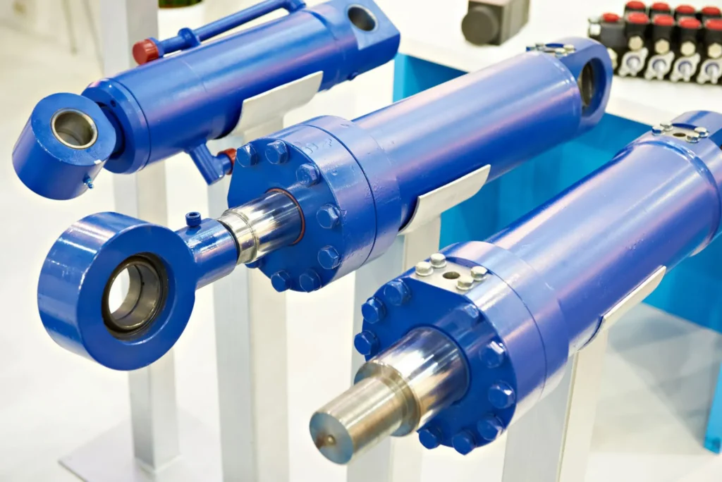
First, use non-negotiable requirements to narrow down the options, then compare costs. If the operating conditions require a large axial force, the working space is limited, and an existing hydraulic power source can provide the necessary pressure and flow rate even during simultaneous operation, hydraulic cylinders should be evaluated first. If the equipment places greater emphasis on multi-point positioning, frequent changes to the motion curve, or reducing the number of hydraulic lines at the workpoint, and if the electric screw candidates pass verification for force-velocity characteristics, duty cycle, and failure mode, then electric screws should be evaluated first. For equipment requiring both heavy-duty capacity and precise control, compare complete solutions that include feedback, protection, and control systems; do not base your decision solely on the drive type.
When submitting an engineering evaluation, condense the information into four categories: Motion (push/pull force at each stage, speed, stroke, dwell time, and cycle); Installation (drawings, available space, orientation, guidance, and environment); Existing Infrastructure (hydraulic supply and return oil conditions or available power supply, controllers, and wiring); Acceptance Criteria (permissible positional errors, force measurement points, permissible displacement after power loss, and recovery methods). If both solutions meet these requirements, compare procurement, integration, and operating costs within the same timeframe. When further discussion of the hydraulic cylinder solution is needed, submit this information along with the equipment drawings to GY Hydraulic.
Choosing a Trusted Hydraulic Cylinder Manufacturer
From standard hydraulic cylinders to custom solutions, we help you improve equipment performance, delivery reliability, and batch consistency
Explore Rivmate Cases

Hey There, I'm Melody!
We are a hydraulic cylinder manufacturer. For over 20 years, we have focused on producing reliable hydraulic cylinders. Need a hydraulic cylinder solution? Feel free to contact us.