
Home / What Causes A Hydraulic Cylinder To Chatter
What Causes A Hydraulic Cylinder To Chatter
- Author: GY Hydraulic
- 20+ Years of Manufacturing
Hydraulic cylinder chatter is usually associated with air ingress, restricted oil flow, unsuitable fluid condition, uneven seal friction, unstable valve control or mechanical jamming. The phenomenon you observe may be the hydraulic cylinder moving a short distance and then stopping, or the load may vibrate repeatedly, accompanied by a knocking sound or a high-pitched noise. Chatter is a symptom of a fault; one should not conclude that the hydraulic cylinder needs replacing based solely on the sound.
When determining the cause, first note whether it occurs when the system is cold or hot, during extension or retraction, and throughout the entire stroke or at a specific position; then check the oil supply and installation conditions. This GY Hydraulic guide follows this approach to help you understand the various causes, organise your inspection sequence, and avoid masking the problem by repeatedly bleeding the system or increasing the pressure.
Table of Contents
What Hydraulic Cylinder Chatter Looks and Sounds Like
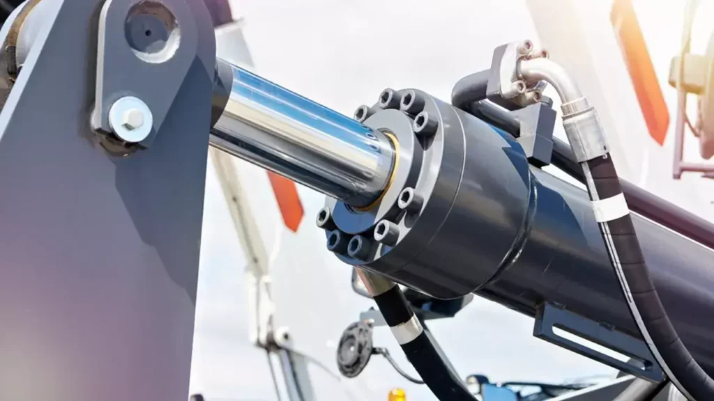
Hydraulic cylinder chatter refers to the repeated occurrence of erratic vibrations or jerks during movement. You can observe the piston rod—the metal rod that extends from the cylinder body and drives the load—from a safe position: does it move at a constant speed, or does it pause briefly before jerking suddenly? If the piston rod moves smoothly, but a humming noise is coming from a nearby valve or pipe, you should first locate the source of the noise; do not immediately assume it is hydraulic cylinder chatter.
Sound can provide a sense of direction, but it cannot, on its own, prove the cause. For example, a thud during directional change may stem from play in the pins; continuous pauses and jerks during low-speed movement may be related to friction; whilst a persistent sound resembling the clattering of gravel near the pump indicates that the oil supply conditions need to be checked. The same sound may also travel along the pipework and frame, leading you to misjudge its location.
You can record a video outside the safety zone that captures both the movement and the sound, whilst noting the direction of movement and the approximate location. Do not place your hand on the piston rod, pins or hoses to ‘feel the vibration’, nor should you allow faulty equipment to continue running solely for the purpose of recording the fault.
Trapped Air and Incomplete System Bleeding
Trapped air refers to air that has not been expelled in a timely manner and remains within a hydraulic cylinder or pipework. As it is more compressible than hydraulic oil, when oil is supplied, the gas may be compressed first, with the load only moving afterwards; this manifests as a sluggish response, jerky movement or sudden surges. Such issues should be given priority consideration if you have recently replaced hoses, disassembled and reassembled a hydraulic cylinder, or if the system has previously been low on oil.
First, consult the equipment manual for bleeding locations, permitted orientations and operating conditions. Some designs require the use of dedicated bleed ports; others permit reciprocating motion under specified loads, at low speeds and at specified pressures. Do not loosen pressurised fittings to bleed air yourself, nor assume that ‘rapidly moving the cylinder back and forth through its full stroke’ will be more effective. Rapid pressurisation of oil containing air may cause localised overheating and damage seals; bleeding requirements must not be overlooked, particularly during the first operation.
For example, if jerky movement occurs after replacing a hose and improves following proper bleeding, this indicates that air may have been a contributing factor to the fault. If the problem recurs shortly after improvement, the source of air ingress should be investigated further; repeated bleeding will not resolve air leaks on the suction side or issues where air is continuously being drawn into the reservoir.
Cavitation, Aeration, and Inlet Restrictions
Both air ingress and cavitation can cause erratic operation, but the checks you need to carry out differ. The most practical way to distinguish between them is to first check whether air is continuously entering the hydraulic fluid, and then to check whether the local oil supply is unable to keep up with demand.
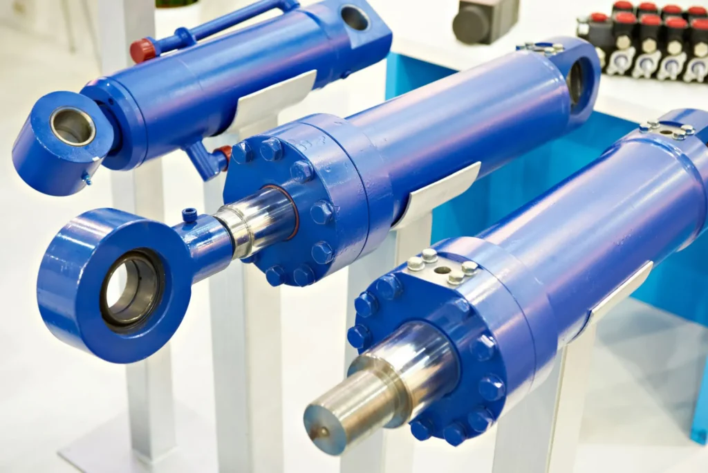
Distinguishing the Three Conditions
Aeration usually refers to air being mixed into the hydraulic fluid in the form of bubbles. Cavitation, on the other hand, is associated with the formation of voids due to locally low pressure; when pressure is restored, the collapse of these voids may cause noise, shock and surface damage. Dissolved air may also be released in hydraulic fluid, meaning that both gas and vapour voids may be present on site; therefore, it cannot simply be assumed that ‘seeing foam means cavitation’.
| Situation | What you may observe | What to check first |
|---|---|---|
| Trapped air after disassembly/reassembly | Jerky initial movement, followed by a sudden movement after a delay | Whether the venting procedure required for this assembly has been completed |
| Air continuously entering the fluid | Recurring foam that reappears even after bleeding | Oil level, suction-side seals, and the layout of the tank return and suction lines |
| Cavitation caused by localised low pressure | Abnormal noise near the pump or valve, worsening at certain speeds or under certain loads | Suction resistance, fluid viscosity, localised throttling and make-up flow capacity |
These are clues for troubleshooting; they are not diagnostic conclusions that can be confirmed by appearance alone. A whitish appearance in the hydraulic fluid may also be related to water contamination and requires further investigation; it cannot be directly attributed to air ingress.
Check Both Pump Supply and Cylinder Replenishment
During a safety inspection after shutdown, you should first check whether the suction hose is kinked, crushed or deteriorated, and verify that the specified filters and tank breather are not blocked. The breather allows the tank to exchange air with the outside environment as designed. When the suction side is under negative pressure, a poor seal may result in only air being drawn in, with no obvious oil traces visible externally; the absence of an oil leak does not rule out air ingress.
You should also consider whether the load is actively pulling on the hydraulic cylinder. For example, when a heavy load is being lowered, the load may pull the piston at a rate faster than the oil supply can keep up with, resulting in insufficient replenishment of the chamber requiring oil. In such cases, the lowering control and replenishment circuits should be checked; one should not focus solely on the pump’s suction line. Do not remove the filter screen, replace it with a finer suction filter element, or bypass the load-holding device without authorisation; these actions may increase resistance or result in a loss of load control.
Contaminated or Incorrect-Viscosity Hydraulic Fluid

Viscosity can be understood as the ‘thickness’ of a fluid as it flows. Cold oil is generally thicker and offers greater resistance as it flows through the suction pipe and valve orifices; oil that is overheated or too thin, on the other hand, may increase internal leakage and impair lubrication. You need to check the equipment’s permitted oil types, start-up temperature and operating viscosity range, rather than simply relying on the viscosity grade stated on the container. The temperature requirements for a particular pump cannot be directly applied to all hydraulic systems.
Contamination can also affect operation. Particles may cause the valve spool—the moving part that regulates the oil flow within the valve—to move unevenly; moisture and oil degradation by-products may also damage lubricated surfaces. You should first check whether the wrong oil has been added recently, whether incompatible oils have been mixed, and whether the filter has triggered an alarm. A normal colour does not guarantee that the fluid is sufficiently clean; if contamination is suspected, samples should be taken in accordance with specifications to test for particulates, moisture and viscosity.
For example, if equipment only experiences surging during winter start-ups, which improves after warming up as per the manual, this may be related to low-temperature viscosity; however, the suction restriction should also be checked. Do not simply add a diluent or switch to a thinner oil on your own; oil selection must also take into account hot-engine lubrication, pump requirements and seal compatibility.
Seal Friction, Stick-Slip, and Damaged Wear Surfaces
If you observe a distinct ‘stop–jerk–stop’ pattern at low speeds, you should focus on the possibility of stick-slip, whilst also checking that the oil supply and control are stable. Stick-slip is a phenomenon whereby moving parts alternate between sticking and slipping; it does not necessarily mean that the seal has worn out.
a. Understanding Why the Rod Jumps
To set a stationary component in motion, the friction at start-up must be overcome; once sliding begins, friction may decrease. As the hydraulic thrust gradually increases, the piston rod moves forward suddenly when the resistance is finally overcome. If the oil supply, friction and system elasticity interact, this process may recur. This jerky motion is particularly noticeable at low speeds.
Therefore, when selecting a hydraulic cylinder for smooth, low-speed motion, one must not merely ask ‘Is the seal friction low?’, but must also consider the difference in friction between start-up and steady-state sliding. Hänchen’s technical documentation also emphasises this point. If your process requires slow feed rates or precise positioning, you should provide the hydraulic cylinder supplier with the minimum operating speed and start-stop patterns.
b. Match the Symptoms to the Inspection
You can note whether the jerking occurs at the moment of start-up after every pause, or whether it always occurs at the same point in the stroke. In the former case, it is worth checking the start-up friction, dwell time and control response; in the latter case, you should also check for surface damage at the corresponding position, the straightness of the rod and any jamming in the mechanism. Problems occurring at a fixed position are merely clues to the location of the issue and do not directly prove that the cylinder barrel is scratched.
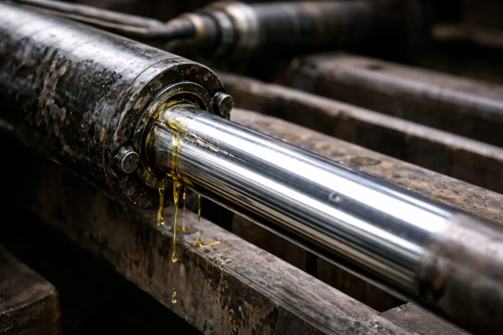
Piston seals are responsible for preventing fluid from flowing from one side of the piston to the other, whilst piston rod seals prevent fluid from leaking out along the rod. The symptoms of damage to these two types of seals may differ. Worn seals may primarily cause internal leakage, loss of force or poor position holding; incorrect dimensions, assembly damage or abnormal expansion, on the other hand, may increase friction. Do not automatically equate ‘old seals’ with ‘high-friction judder’.
c. Select Seals and Surface Repairs Together
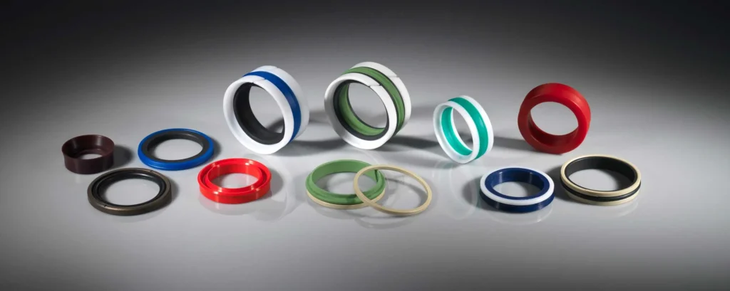
Check More Than Just Seal Dimensions
When selecting seals, you should simultaneously verify the dimensions of the seal groove, the material, the fluid, the temperature, the pressure and the speed of movement. Guide rings are used to support the piston or piston rod and reduce direct metal-to-metal contact; their load-bearing capacity must also be matched to the actual operating conditions. Simply replacing a set of seals with ones of similar dimensions will not rectify guide wear or misalignment during installation.
For example, where a piston rod exhibits obvious scuffing on one side, maintenance personnel should inspect the guide clearance and the direction of force, rather than simply grinding away the scratches. The surface roughness, texture and dimensions of the seal contact surfaces must conform to the specific design; ‘the shinier the better’ is not a universal rule.
Insufficient Flow, Valve Instability, and Pressure Settings
First, distinguish between flow rate and pressure: flow rate is the volume of oil passing through per unit of time, and primarily affects the speed of movement; pressure must be considered in conjunction with the effective areas on either side of the piston and the resistance to determine whether the load can be moved. A consistently low oil supply typically results in slow movement; however, noticeable jerking may only occur if the oil supply is intermittent, the valve opens and closes repeatedly, or the thrust is just sufficient to overcome the resistance.
For example, in a hydraulic cylinder with a bore diameter of 50 mm, when a steady flow of 3 L/min is supplied to the rodless chamber—that is, the side of the piston without the rod—the theoretical extension speed is approximately 25.5 mm/s. This calculation disregards leakage and fluid compressibility; it is intended solely to illustrate the relationship between speed and flow rate and does not constitute a criterion for determining chattering. Halving the flow rate will halve the theoretical speed, but this does not necessarily result in stop-and-go motion.

With regard to valves, relief valves are used to limit pressure, whilst balancing valves are used to maintain and control load descent within the relevant circuit. If valves are damaged, incorrectly selected, or if the pilot pressure required to open the control valve fluctuates repeatedly, these factors may all contribute to vibration. If there is noticeable jerking during descent, the load control circuit requires particular attention. The pilot ratio of the balancing valve—that is, the proportional relationship between the pilot pressure and the valve’s opening action—affects stability; therefore, selection should not be based on the principle that ‘the higher, the better’.
You should first retain the original settings and fault records, then have maintenance personnel measure the relevant pressure, flow rate and electrical control signals. Do not simply turn up the relief valve or artificially increase the return flow resistance; the back pressure created by return flow resistance will alter the actual thrust and the operating conditions of the valves, potentially introducing new problems.
Side Load, Misalignment, Loose Mounts, and Bent Rods
A lateral load is a transverse force acting at an angle to the direction of movement of the piston rod; misalignment, on the other hand, refers to a situation where the direction of movement of the hydraulic cylinder is not correctly aligned with that of the mechanism being actuated. Both can cause the guiding surfaces to bear the load on one side only, increasing friction and damaging the surfaces. The amount of lateral force a hydraulic cylinder can withstand depends on its design; the piston rod must not be used as a machine guideway.
Once the load has been safely supported and the equipment has been shut down and isolated, you should inspect the mounting bracket, pins, bushings and fastenings for any looseness, uneven wear or cracks. For example, if there is a clicking sound followed by a delay in movement each time the direction is reversed, the connection clearances should be checked; if resistance consistently increases at a particular position, the mechanism should be checked for interference, alignment and the condition of the components. These issues cannot be resolved simply by replacing the seals.
Inspections must cover the entire range of the mechanism’s motion, rather than merely checking alignment whilst the mechanism is stationary. If piston rod bending is suspected, it should be measured by maintenance personnel after the machine has been shut down; do not remove pins, loosen mounting brackets or tap the piston rod on site to ‘align’ it whilst under load.
A Step-by-Step Process to Diagnose Chatter
The correct sequence for troubleshooting is as follows: first, confirm whether it is safe to observe; then record the conditions; next, take measurements; and finally, verify the repair. You do not need to dismantle the cylinder straight away, but you must not allow equipment that poses a risk of losing control to operate repeatedly in order to collect data.
Step 1: Record When the Chatter Occurs
If the equipment permits a controlled inspection to proceed, record the details in the table below from outside the safety zone. Compare only one condition at a time; for example, the behaviour of the machine when cold versus when hot, under the same load and position. Do not alter speed, load and valve settings simultaneously, as it will otherwise be difficult to determine which change was responsible.
| Item to Record | Specific Details | How it helps narrow down the scope |
|---|---|---|
| Temperature | Oil temperature reading and measurement location; do not simply write ‘cold’ or ‘hot’ | Viscosity, leakage when the cylinder is warm, and temperature-related friction |
| Direction and Load | Extension, retraction, ascent or descent, and load status | Oil supply path, load control and differences in force |
| Stroke Position | Just started, fixed section, full stroke or near end-of-stroke | Start-up friction, localised damage or end-of-stroke cushioning |
| Speed and Other Actions | Low or normal speed; whether other actuators are operating simultaneously | Low-flow control and oil supply distribution |
| Noise and History | Approximate location of noise; whether oil, hoses or seals have recently been replaced | Inspection priorities and maintenance-related factors |
For example, “After replacing the seals, there is a jerk during low-speed extension, but this is not noticeable at normal speed” is more diagnostically valuable than “the hydraulic cylinder is constantly vibrating”. However, this still does not rule out unstable low-flow valve control, which requires further verification.
Step 2: Check the Basic External Conditions
First, shut down the machine in accordance with regulations, support the load, isolate the power supply and relieve residual pressure, then check the oil level, oil quality records, the appearance of the pipework, filter indicators and installation connections. The oil level must be read at the cylinder position and equipment orientation specified in the manual, as the extension and retraction of the piston rod will alter the oil volume in the reservoir. If a low oil level is observed, it is also necessary to ascertain whether this is due to a leak, insufficient maintenance or incorrect reading conditions.
If the fault occurs immediately following a repair, first verify the changes made during that repair. For example, after replacing hoses, check whether the pipework has been connected incorrectly, kinked or whether fittings are not properly connected; after replacing seals, verify the kit and assembly requirements. Do not rule out a new part or its installation process simply because it has just been fitted.
Step 3: Measure Before Adjusting
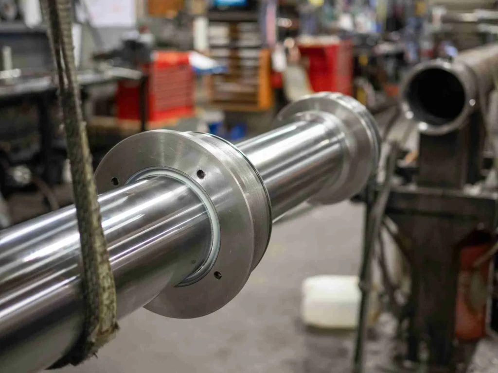
Checks on pressure, flow and electrical signals should be carried out by maintenance personnel with the appropriate qualifications. Pressure measurement points should be selected in accordance with the circuit layout; where necessary, observe both chambers of the hydraulic cylinder. Measuring only at the pump outlet may fail to reveal localised pressure variations caused by pressure drops in the pipework or the load. For rapid vibrations, standard analogue gauges may only display average values; therefore, a measurement method capable of capturing fluctuations must be selected.
When selecting instruments, verify the range, pressure rating, temperature rating, resolution and response time. When measuring low flow rates during slow-speed operations, do not rely solely on the flow meter’s maximum range; when measuring suction-side pressure, use instruments capable of measuring the corresponding low-pressure or vacuum ranges. All temporary connections must have clearly specified ratings; do not use ordinary transparent hoses as pressure-bearing observation tubes.
Step 4: Confirm the Cause with Comparable Results
Have maintenance personnel compare motion, pressure, flow and control commands side by side. If multiple hydraulic cylinders exhibit abnormalities simultaneously, the shared oil supply and control system warrant priority investigation; if only one cylinder is sticking in a fixed position, a localised mechanical issue takes precedence. This is merely a sequence of checks and does not replace isolation testing.
Following repairs, re-examine the movements that were originally most prone to flutter under approved test conditions. For example, after rectifying an issue with oil inflow during cold start-up, verification should be carried out in accordance with the permitted cold start-up procedure, rather than merely testing once whilst the machine is warm. It is essential to confirm not only that the jerking has improved, but also that speed, leakage, temperature rise and load control comply with the equipment’s requirements; simply noting that ‘the noise has reduced’ is not sufficient to deem the system fully compliant.
Corrective Actions for Hydraulic and Mechanical Causes
For oil supply or air-related issues, address the source first, then complete the bleeding procedure. You must restore the specified oil level, repair any intake or oil leaks, and resolve any identified line restrictions. Filter elements must match the original design’s flow rate, filtration requirements and pressure differential conditions; the pressure differential is the difference in pressure before and after the filter element, so selection should not be based solely on the assumption that ‘the finer the filtration, the better’. Thereafter, bleed the system in accordance with the manual and re-inspect it to prevent fresh air from entering.
For fluid or control issues, take action based on the test results. In the event of incorrect fluid selection or contamination, determine whether an oil change, flushing or further maintenance is required; where valves are unstable, verify part numbers, control signals and original settings. For example, if the fault only occurs when multiple actions are operating simultaneously, verify the flow distribution first, rather than immediately purchasing larger hydraulic cylinders. After adjusting control parameters, also check whether other machine functions have been affected.
For friction or mechanical issues, the damage and its underlying causes must be rectified together. You may need to replace seals and guide components that meet the specifications, repair mating surfaces to within acceptable tolerances, or correct the installation geometry. If the thrust capacity is close to the load requirement, the cylinder bore, rod diameter and installation conditions must also be recalculated; simply increasing the cylinder bore will alter the required flow rate and speed. The repair plan should address the identified causes, rather than replacing multiple parts simultaneously and then guessing which one was effective.
When Chatter Means the Machine Should Be Stopped
If flutter is accompanied by a sudden drop in load, loss of control, noticeable movement of the mounting base, structural cracks, suspected bending of the piston rod, or bulging hoses and oil spray, operations must be halted immediately in accordance with the equipment procedures. These phenomena relate to load-holding capacity or structural integrity, and it is not appropriate to continue trial operation under load. Persistent loud noise accompanied by abnormal temperature rises or alarm signals should also prompt a shutdown for investigation; do not rely on repeated cycling in the hope that the issue will resolve itself.
Keep personnel away from the load and any areas where the mechanism may move; place the equipment in a safe state in accordance with procedures, and then apply the specified support and isolation measures. Shutting down the pump does not necessarily mean that the system has been depressurised; the load, accumulator or oil circuits sealed by valves may still store energy. An accumulator is a device for storing hydraulic energy and must be handled in accordance with its specified procedures.
Do not use your hands to locate high-pressure leaks, nor connect fittings whilst the system is under pressure. Even a fine stream of oil can penetrate the skin; if you suspect a hydraulic oil injection injury, seek emergency medical treatment immediately—do not treat it as a minor cut. Guidance from the UK Health and Safety Executive (HSE) explicitly requires safe pressure relief and the use of appropriate mechanical supports.
If you need to consult GY Hydraulic regarding hydraulic cylinder configuration or maintenance requirements, please have the nameplate, installation photographs, fluid grade, circuit diagram and conditions under which the vibration occurs to hand. Where pressure or flow records are available, please also specify the measurement points, fluid temperature and load conditions; this information is more helpful for diagnosis than simply describing the hydraulic cylinder as ‘making an unusual noise’.
FAQs
Will bleeding the hydraulic system always stop chatter?
Not necessarily. Bleeding is effective for motion instability caused by air ingress, but it cannot rectify mechanical binding, stick-slip in seals or valve-induced oscillation. You should compare performance before and after bleeding; if the problem recurs quickly, continue to investigate the source of the air ingress rather than repeating the bleeding process endlessly.
Can low hydraulic fluid cause a cylinder to chatter?
Yes. A low fluid level may cause air to be drawn in through the suction port, or create vortices in the reservoir that entrain air, affecting the stability of the fluid supply. You should first check the fluid level in the correct operating position, then top up with the specified fluid and investigate the cause of the low level to avoid overfilling whilst the system is in the wrong position.
Can a bad relief valve cause jerky cylinder movement?
Yes, but not all jerky movements are caused by the relief valve. Sticking or damaged valves, or pressure settings that do not match operating conditions, may cause instability in pressure or available flow. A maintenance technician should verify whether pressure fluctuations are synchronised with the jerky movements and inspect the condition of the valve; it should not be replaced solely on the basis of noise near the valve.
What is the difference between chatter and cavitation?
Chatter describes the vibration and erratic movement that you can see or feel; cavitation describes the physical phenomenon of cavitation forming due to localised low pressure. Cavitation may cause noise and abnormal movement, whilst chatter may also be caused by friction or installation issues; therefore, the oil supply conditions and mechanical movement should be inspected separately.
Can increasing pressure fix hydraulic cylinder chatter?
Increasing pressure should not be treated as a universal remedy. If the original pressure does not meet the equipment’s requirements, the correct setting should be restored in accordance with approved procedures; if the problem stems from air ingress, sticking or unstable valves, increasing pressure may temporarily move the load but increases the risk of stress and damage. Measure and verify the requirements first, then decide whether an adjustment is necessary.
Why does a hydraulic cylinder chatter only when cold?
Common areas to investigate include low-temperature fluid viscosity, suction restrictions, and low-temperature friction at sealing and guiding points. You should record the actual fluid temperature and its changes during the warm-up process, and check against cold-start requirements. If the issue resolves after warm-up, this merely indicates that the fault is temperature-related; it does not automatically prove that the wrong fluid grade has been selected.
Can worn seals make a hydraulic cylinder vibrate?
It is possible. Leaks caused by seal wear, or uneven friction resulting from seal damage, may both contribute to abnormal movement; however, oil leakage does not necessarily cause vibration. You should assess the situation by considering the leakage, thrust, speed and maintenance history before deciding whether to dismantle and inspect the cylinder; do not purchase a seal kit based solely on the presence of chatter.
How can I tell whether chatter is hydraulic or mechanical?
You can start by observing patterns: if multiple actuators exhibit abnormalities simultaneously, prioritise checking the shared oil supply and control systems; if there is sticking at fixed positions, one-sided wear or impact at joints, it is more likely that the mechanical components require inspection. However, mechanical binding can also cause pressure fluctuations, whilst hydraulic vibration can cause the frame to shake; ultimately, confirmation requires a combination of measurements and safety isolation checks.
Choosing a Trusted Hydraulic Cylinder Manufacturer
From standard hydraulic cylinders to custom solutions, we help you improve equipment performance, delivery reliability, and batch consistency
Explore Rivmate Cases

Hey There, I'm Melody!
We are a hydraulic cylinder manufacturer. For over 20 years, we have focused on producing reliable hydraulic cylinders. Need a hydraulic cylinder solution? Feel free to contact us.