Home / What Is A Rephasing Hydraulic Cylinder
What Is A Rephasing Hydraulic Cylinder
- Author: GY Hydraulic
- 20+ Years of Manufacturing
A rephasing hydraulic cylinder is a hydraulic cylinder fitted with a dedicated bypass channel or resynchronisation valve, designed to assist a set of matched hydraulic cylinders in realigning their positions. The piston is the component within the cylinder that receives hydraulic pressure and drives the piston rod; the stroke is the effective distance travelled by the piston rod. In common series-connected systems, the cylinders coordinate their movement through matched fluid volumes; upon reaching the designed end of stroke, the bypass mechanism allows fluid to continue flowing, enabling cylinders that have not yet reached their final position to complete the remaining stroke, thereby correcting cumulative positional errors.
You can think of it as ‘reliance on volumetric coordination during motion, with realignment at specified positions’. It is not an electronic system capable of real-time correction at any position, nor can it rectify issues such as incorrect sizing, mechanical jamming or severe leakage. This GY Hydraulic guide primarily explains common double-acting series resynchronisation systems; ‘double-acting’ means that both extension and retraction are driven by hydraulic fluid, whilst other connection configurations require assessment based on the specific circuit.
Table of Contents
What a Rephasing Hydraulic Cylinder Does
The purpose of resynchronisation is to correct the gradually accumulating positional deviations in a set of hydraulic cylinders. The term ‘phase’ here refers to whether the cylinders are in the relative positions specified by the design, not to electrical phase. For example, on a wide-body agricultural machine, both sides were originally designed to rise and fall together; however, after a period of use, one side may become slightly higher than the other, and a resynchronisation cycle may help restore their relative positions.
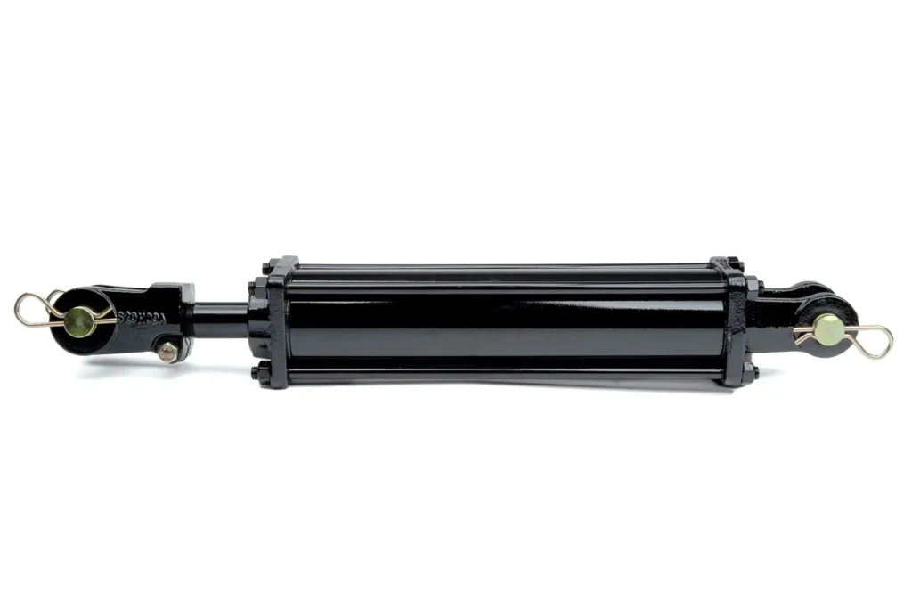
A characteristic of such systems is that they combine the normal flow of hydraulic fluid with the correction of errors at specified positions. Whilst ordinary hydraulic cylinders can also drive loads, if a suitable resynchronisation circuit is lacking, the cylinder that reaches the end point first in a series system may block the subsequent fluid path, preventing other cylinders from continuing to their intended positions. A resynchronisation mechanism provides a specifically designed fluid pathway to address this situation.
To determine whether this is suitable for your application, first confirm whether the equipment has the opportunity to reach the resynchronisation position as required, and what degree of deviation is permitted at intermediate positions. If the mechanism operates exclusively in a back-and-forth motion within the middle section of its stroke for extended periods, and is rarely able to reach the correction position, one cannot expect end-point resynchronisation to continuously eliminate errors. Furthermore, functionality must be verified through model specifications and drawings; not every group of hydraulically mounted cylinders can be termed ‘resynchronisation cylinders’.
How Rephasing Cylinders Synchronize in a Series Circuit
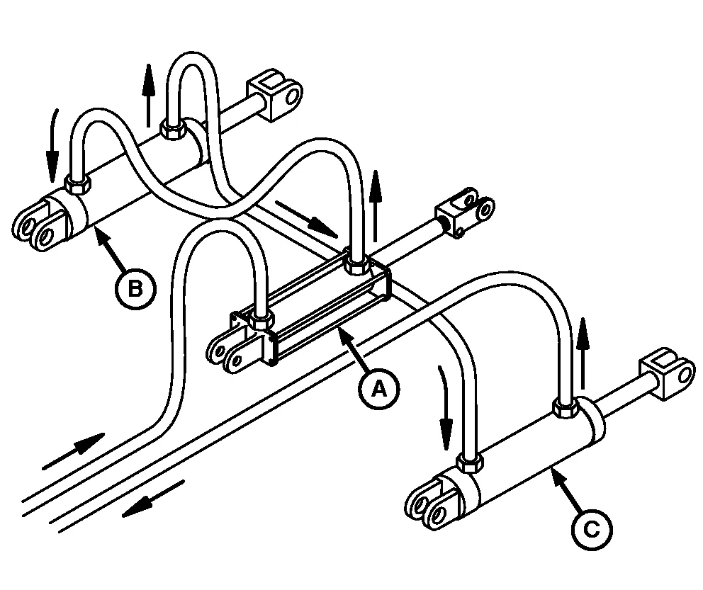
Common series systems utilise the oil discharged from the preceding cylinder to drive the subsequent one. As they do not simply branch off from the same supply line at random, the connection sequence and the areas of the two chambers directly influence their motion relationship.
a. Follow the Oil Path
First, let us define two positions: the rodless chamber is the side of the piston without a rod, whilst the rod chamber is the side where the piston rod occupies part of the space. In this article, following the oil supply sequence during normal extension, the front cylinder is referred to as the master cylinder A, and the rear one as the slave cylinder B. For the common configuration where ‘the rod chamber of one cylinder connects to the rodless chamber of the next’, the flow path during extension is as follows:
| Oil Path | What Happens | Key Relationship to Understand |
|---|---|---|
| Control valve supplies oil to the rodless chamber of Cylinder A | Cylinder A piston rod extends | As Cylinder A moves, oil is discharged from the rod chamber |
| Rod chamber of Cylinder A connects to the rodless chamber of Cylinder B | Discharged oil drives Cylinder B to extend | The discharge volume from Cylinder A must match the inflow volume to Cylinder B |
| The rod chamber of Cylinder B returns fluid via the corresponding control line | Cylinder B can continue to move | The return path and control conditions must also meet the requirements |
The table above merely explains the operational relationship of one type of circuit; it is not a general-purpose piping layout drawing. PTE’s documentation on resynchronisation cylinders also states that the fluid discharged from the rod end of the preceding cylinder supplies the piston end of the next cylinder; coordinated extension and retraction can only be achieved after matching the volumes.
b. Match Volume Before Expecting Equal Travel
The piston rod occupies part of the space in the rod chamber; therefore, when a standard single-rod cylinder moves the same distance, the volume of oil discharged and admitted on either side differs. This is precisely why two hydraulic cylinders of the same bore cannot be connected in series arbitrarily; bore refers to the working internal diameter of the cylinder barrel. If the oil discharged by the front cylinder after moving a certain distance is insufficient to allow the rear cylinder to move the same distance, the rear cylinder will lag behind.
During reverse motion, the fluid is transferred in the opposite direction along the corresponding connections, so the matching relationship remains crucial. However, ‘the two cylinders retracting in unison’ does not mean that the system’s retraction speed must necessarily be the same as the extension speed; the supply area may differ in the two directions. You should verify the speed and force requirements for extension and retraction separately.
c. Separate Rod Motion from Machine Motion
Even if both rods move the same distance, the two sides of the equipment may not rise by the same amount, as the installation angle, lever length and connection position may differ. For example, the same rod stroke applied to rocker arms of different lengths will result in different angular changes. When selecting a model, both the hydraulic connection diagram and the mechanical mechanism diagram should be provided; the levelness of the entire machine cannot be guaranteed solely on the basis of ‘rod synchronisation’.
The Role of the Internal Bypass or Rephasing Port
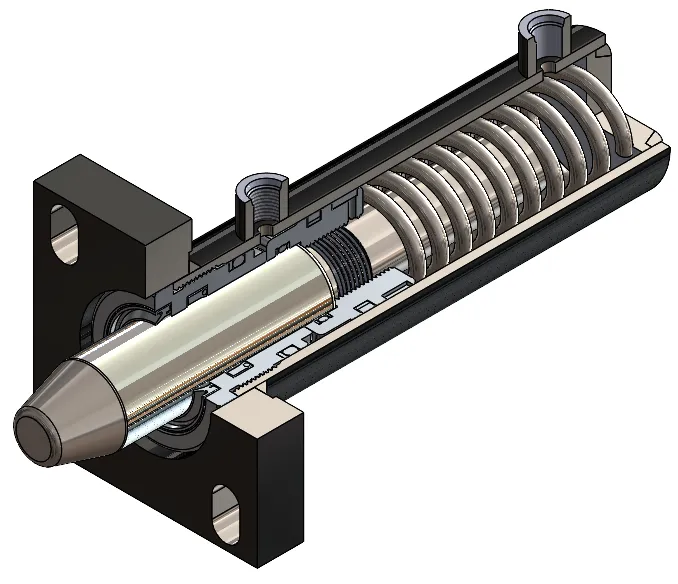
A resynchronisation mechanism provides a passage for hydraulic fluid at a specified position, allowing it to bypass the normal sealing isolation on either side of the piston. This passage may take the form of a machined groove in the cylinder barrel, an internal channel, or a dedicated valve in the piston; it is not necessarily an externally visible ‘port’ to which a hydraulic hose can be connected. For example, the relevant equipment manual from Schulte explains that a resynchronisation groove in the cylinder barrel forms a bypass across the piston’s main seal when the piston is fully extended.
It typically functions only at specified end-of-stroke positions—either extension, retraction or both—and not all resynchronisation cylinders are capable of correcting in both directions at their end positions.
When carrying out maintenance or testing, you should first ascertain when the bypass is activated. If the expected bypass occurs at the designed resynchronisation position, this should not be automatically interpreted as seal failure; however, if unauthorised cross-leakage persists after moving away from that position, further inspection is required. Furthermore, do not seal the bypass orifice yourself to ‘enhance pressure retention’, nor enlarge the groove to accelerate correction, as this will alter the functionality of the entire system.
Master, Slave, and Matched-Displacement Cylinder Sizing
The core of master-slave cylinder dimensioning lies in matching the oil discharge volume with the receiving volume under the target motion. Here, ‘displacement matching’ refers to the volume of oil discharged or drawn in by the hydraulic cylinder over a given stroke; it is not merely a comparison of external dimensions, bore diameter or rated thrust.
a. Start with the Connected Working Areas
Taking the example where the rod chamber of Cylinder A is connected to the rodless chamber of Cylinder B, and both cylinders are required to move an equal distance, the following condition must be satisfied during the normal operating range, whilst neglecting leakage and fluid compression:
Effective area of Cylinder A’s rod chamber × Displacement of Cylinder A = Effective area of Cylinder B’s rodless chamber × Displacement of Cylinder B
The effective area is the working cross-sectional area of the fluid within that chamber. When the displacements of the two cylinders are equal, the effective areas of the two connected chambers must match. Let the bore diameter of cylinder A be D₁ and the rod diameter be d₁; let the bore diameter of cylinder B be D₂; the rod diameter refers to the diameter of the piston rod. The ideal relationship for this connection is:
π × (D₁² − d₁²) ÷ 4 = π × D₂² ÷ 4
In other words, you must subtract the area occupied by the piston rod from the total piston area of the front cylinder, and then compare this with the total piston area of the rear cylinder. If the design objective involves different strokes or different motion ratios, it is also necessary to calculate the target displacement and the mechanical relationship; the condition of equal displacement cannot be applied directly.
b. Work Through a Geometry Example
The following is merely an example of an idealised geometric calculation; it is not based on actual measurements, nor does it constitute a recommended purchase specification. Assuming Cylinder A has a bore diameter of 100 millimetres and a rod diameter of 60 millimetres, whilst Cylinder B has a bore diameter of 80 millimetres, and disregarding leakage, compression and pipe elasticity:
| Comparison Item | Cylinder A (with rod chamber) | Cylinder B (without rod chamber) |
|---|---|---|
| Diameter used for calculation | Cylinder bore 100 mm, rod diameter 60 mm | Cylinder bore 80 mm |
| Effective area | Approx. 5026.5 square millimetres | Approx. 5026.5 square millimetres |
| Volume of fluid displaced by a 10 mm piston stroke | Approximately 50.3 millilitres | Approximately 50.3 millilitres |
Therefore, during the normal stroke, when cylinder A moves 10 mm, the volume of fluid displaced—under ideal conditions—would allow cylinder B to move 10 mm as well. If you were to replace B directly with a cylinder of 100 mm bore, the same volume of oil would only allow it to move approximately 6.4 mm. End-point synchronisation can align the end-points, but it cannot eliminate this geometric proportional error that occurs with every stroke.
c. Check the Rest of the Cylinder Set
Confirm Stroke, Order, and Rephasing Position
Area matching only resolves part of the problem; you must also verify the stroke, mounting centre distance, series sequence and bypass position for each cylinder. The mounting centre distance is the distance between specified mounting reference points and is not equivalent to the total length of the cylinder. In a multi-cylinder series configuration, oil from one cylinder may continue to be supplied to the next; therefore, one cannot simply calculate the first pair and assume the entire chain is correct.
Replacement parts must be verified against the complete machine’s part numbers and versions. For example, Landoll’s equipment manual records that, following design changes to the supplier’s resynchronisation cylinders, the part numbers for the cylinders and service parts have changed, and requires that markings be checked when ordering. This illustrates that even within the same equipment series, old and new parts cannot be interchanged based on appearance alone. Landoll resynchronisation cylinder version identification instructions
Check Pressure and Load in Both Directions
A series configuration does not imply that each cylinder is subjected to the same pressure, nor does it mean that the design is complete simply by listing the same rated pressure for each cylinder. The pressures in the front and rear chambers and the loads on each cylinder influence one another; it is necessary to verify the local pressures and available thrust and pull forces across the entire stroke, in both directions, and under resynchronisation conditions. Pressure may increase under certain operating conditions; therefore, the safety of each cylinder port cannot be determined solely by the pump outlet reading.
Provide the supplier with details of load variation with position, required speed, oil supply and return conditions, as well as the dimensions and connection relationships of all cylinders. The example calculation above does not specify the rod diameter, stroke, pressure rating or mounting configuration of Cylinder B; therefore, it cannot be used directly for complete product selection.
How a Rephasing Cycle Corrects Position Error
A typical end-point resynchronisation process is as follows: each cylinder first moves towards the specified correction end, with one of them reaching its position first; once its resynchronisation channel opens, the hydraulic fluid can continue to flow as designed, allowing the cylinders that have not yet reached their positions to complete their remaining stroke. Once all cylinders have reached the specified reference position, the previously accumulated positional difference is corrected. This corrects the relative position; it does not restore worn parts to their original condition.
Before proceeding, you should first ascertain whether this model utilises re-synchronisation via the extended or retracted end, and confirm that the equipment’s orientation, surrounding space and load conditions permit this operation. If stroke stops, depth limiters or external mechanisms prevent the piston from entering the bypass zone prematurely, continuing the manoeuvre may not necessarily achieve correction. Do not remove these limiting devices yourself; they should be handled in accordance with the procedures for the complete unit.
The holding time and flow rate should be determined in accordance with the equipment manual; there is no standard duration applicable to all models. The condition of the hydraulic fluid required for the initial oil filling differs from that required for routine position correction, and the procedures may also vary. Upon completion, exit the resynchronisation position as specified in the manual, then check the coordinated movement within the normal operating range; do not hold the piston at the end point indefinitely to avoid unnecessary heat build-up or pressure strain.
Common Agricultural and Industrial Applications
Resynchronisation cylinders are commonly used in agricultural machinery where multiple positions need to be raised and lowered in coordination, and where there is a possibility of returning to a reference position during operation; examples include depth or height control in wide-track tillage machines, and the co-ordination of multiple lifting points in mowing equipment. Their function is to assist the various components in restoring their designed positional relationships; they do not guarantee perfect alignment under all soil, load and machinery conditions.
This principle may also be considered for industrial equipment, such as multi-point movement mechanisms that allow periodic returns to a reference point and have a clearly defined tolerance for mid-stroke errors. However, the mere presence of ‘two hydraulic cylinders’ should not be the sole criterion for selection. If the equipment cannot reach its end position, the structure is highly rigid, or even minor deviations could cause jamming, solutions such as mechanical synchronisation, flow-splitting control or electronic position feedback should be evaluated first.
When screening applications, you may list four criteria: the stroke range requiring synchronisation, the permissible positional deviation, the opportunity to return to the synchronisation position, and load variations. The synchronisation function cannot automatically ensure load retention; where suspension, the carriage of persons, or personnel entering beneath raised components is involved, corresponding safety design for the entire machine is also required.

Circuit Design, Plumbing, and Bleeding Requirements
First, check the model drawings to confirm the identity of each cylinder, the sequence of the series connection and the function of each port, before connecting the pipework. Do not swap the master and slave cylinders or change the original series connection to a standard parallel connection simply because the hose length is just right. The pipework must also meet the requirements for maximum pressure, normal flow rate and operational space; quick-release couplings must be correctly engaged to prevent flow restrictions affecting subsequent cylinders.
Bleeding is related to resynchronisation, but is not the same task. Bleeding removes entrained air; resynchronisation corrects relative positions. Air is easily compressed, causing the volumetric transmission to become temporarily elastic, resulting in jerking, delays or positional shifts. You should first check the reservoir level and ensure the correct fluid is used, then carry out the initial filling and bleeding procedures in accordance with the machine manual; do not mistake a single brief end-point adjustment for thorough bleeding.
For example, specific equipment manuals from Dalton provide dedicated bleeding procedures for the resynchronisation system and warn against bleeding by loosening fittings. Such procedures may involve specialised support, cylinder block orientation and initial commissioning conditions, and should be carried out by trained personnel in accordance with the relevant model. Do not loosen hoses whilst under pressure, or release load-bearing pins to allow the cylinders to move freely.
Accuracy Limits, Load Differences, and Leakage Effects
Volumetric matching provides a ratio of motion; it cannot guarantee zero positional error under all operating conditions. Actual dimensional deviations in cylinder bore and rod diameter, seal leakage, hydraulic fluid compression, hose expansion and variations in friction may all affect relative positioning. Resynchronisation can correct cumulative errors at specified positions, but it cannot replace verification of precision during the normal motion phase.
Uneven loading does not necessarily disrupt the ideal volumetric relationship, though it does alter the pressures in each chamber and the actual operating conditions. If a particular cylinder is subjected to excessive force, abnormal friction or insufficient supply pressure, stalling or a delay following elastic deformation may occur. For example, if one side of the mechanism becomes jammed whilst the other moves briefly, this should not simply be interpreted as ‘the hydraulic fluid automatically selecting the cylinder with the lighter load’; the actual connections, pressure and compression effects should be checked.
Changes in position after coming to rest should also take into account oil temperature and the control circuit. Where the rod continues to move slowly in the absence of an actuation command, this is commonly referred to as ‘drift’. When comparing changes in rod position, measurements should be taken at similar temperatures to avoid misinterpreting temperature variations as leakage. You should record the relative error during motion and the drift after coming to rest separately, and assess them against the requirements of the complete machine; do not make a uniform commitment for the entire system to a specific value in millimetres or a percentage accuracy.
Troubleshooting Cylinders That Fall Out of Phase
First, determine how the misalignment occurred, then decide where to investigate. A consistent proportional discrepancy present from the very first operation typically requires a different troubleshooting sequence to one where the system was initially normal but gradually deviated after use.
Record Movement from a Common Reference
Number the hydraulic cylinders in the order specified in the drawings, and record the model number, rod position, direction of movement, oil temperature and load. When comparing displacement, use the stroke variation of each cylinder relative to its own starting point; do not directly compare the exposed rod lengths, as cylinder heads, rod ends and mounting dimensions may inherently differ.
For example, two rods protruding by the same length do not necessarily mean they have completed the same stroke; nor does an identical stroke variation between two rods imply that the heights on either side of the mechanical assembly are the same. First determine whether you are measuring rod stroke or equipment position; only then will subsequent conclusions be meaningful.
Use the Symptom to Choose the Next Check
| Phenomenon observed | Priority troubleshooting direction | Actionable next step |
|---|---|---|
| After replacing the cylinder, a similar proportional discrepancy occurs with every movement | Mismatch in bore diameter, rod diameter, stroke, connection sequence or replacement version | Verify part numbers and the cross-sectional area of the two connected chambers; avoid measuring stroke alone |
| Returns to correct position after end-of-stroke calibration, but gradually deviates again after a period of operation | Minor leakage, insufficient opportunity for normal calibration, or other sources of cumulative error | Record the cycle and operating conditions in which the deviation occurs, then check against maintenance requirements |
| Movement exhibits elasticity, jerking or noticeable delay at the start | Air or air ingress; friction or lubrication issues may also be present | Check fluid level, whether initial bleeding has been completed, and the condition of fittings |
| Once one cylinder has reached full extension, the others remain unable to do so | Failure to engage the bypass position, obstructed passage, incorrect piping, external forces or insufficient pressure supply | First check for external restrictions and connections against the drawings; then arrange for professional pressure and flow path inspections |
| Consistently jamming at a specific position or suddenly losing coordination | Mechanical interference, lateral forces deviating from the axial line of extension, or localised internal damage | Cease forced operation, record the position and inspect the mechanism and components |
| Significant variation in height after coming to rest | External leakage, internal cylinder leakage, valve circuit leakage or temperature effects | Record the variation at similar temperatures; maintenance personnel should verify the source in stages |
The items in the table are troubleshooting guidelines; they do not constitute a definitive fault diagnosis based solely on observed symptoms. Do not overlook rapid recurrence, abnormal overheating or new oil leaks simply because the system appears ‘temporarily normal’ after resynchronisation.
Check Safely Before Disassembling
First, under conditions of safe shutdown, reliable support and appropriate pressure relief, check for external oil stains, connections, hoses, pins and mechanical interference. If the equipment permits normal resynchronisation, the operator should carry this out in accordance with the model-specific procedure and record the results; if normal operation cannot be restored, a specialist should then inspect the bypass passages, seals and pressures in each section.
Do not resort to trial and error by increasing system pressure, enlarging resynchronisation orifices, removing stroke limiters or temporarily loosening pipes.
Pressure in the master cylinder, slave cylinder and pipework influences one another; even if the main pressure gauge reads zero, this does not prove that all sealed oil chambers have been depressurised. The report should clearly state the fault location, measurement conditions and items verified, to facilitate narrowing down the scope of the next inspection.
When Electronic Synchronization Is a Better Choice
If you require continuous position correction throughout the entire stroke, frequent stops midway, different motion ratios, or strict positional accuracy even under varying loads, you should consider electronic synchronisation. This typically involves using position sensors to measure the actual position of each cylinder; the controller then compares the target position with the actual position and adjusts the motion via the appropriate valves or drive units. This process of continuous measurement and correction is known as closed-loop control.
For example, in a multi-point positioning mechanism that can only operate at mid-stroke and cannot regularly reach the end of its travel, it is difficult to meet continuous correction requirements by relying solely on end-of-stroke bypass. Völkel’s hydraulic cylinder synchronisation control solution utilises position input, target position and proportional output for coordinated control, demonstrating that electronic solutions can be configured to meet specific motion requirements rather than relying solely on geometric displacement relationships.
Electronic solutions also require verification of sensors, valve response, structural rigidity and control commissioning. Sensor resolution—the smallest positional change it can detect—cannot be directly equated with the synchronisation accuracy of the entire machine. You should specify the permissible error over the full stroke, speed, load range, dwell positions and fault response requirements before comparing solutions. Standard position-based closed-loop control does not automatically equate to safety protection; load holding and fault stop functions must still be designed and verified separately.
FAQs: What Is A Rephasing Hydraulic Cylinder
Can rephasing cylinders operate in parallel?
Whilst parallel or paired rephasing circuits designed in accordance with the manufacturer’s specifications may exist, it is not possible to simply connect two cylinders to the same oil supply tee and expect them to automatically achieve equal displacement. It is essential to verify how the specific circuit manages oil flow and rephasing, as well as whether the objective is coordinated movement in the same or opposite directions. The area calculation examples in this article apply only to the series connections described. Aggressive Hydraulics Definition of Rephasing Cylinders
How many rephasing cylinders can be connected in series?
There is no universal maximum number applicable to all products. The number of cylinders that can be used depends on size compatibility, the load on each cylinder, supply and return pressures, venting, the rephasing flow path and permissible tolerances. When adding a cylinder, the entire chain must be re-verified; one cannot simply connect the next cylinder and assume the original design remains valid.
Do rephasing cylinders need identical bore sizes?
Not necessarily. In common equal-displacement series configurations using single-rod cylinders—where the rod chamber of the front cylinder connects to the non-rod chamber of the rear cylinder—the bore of the rear cylinder is typically matched to the effective area of the front cylinder (after deducting the rod area), rather than using the same bore size. Other connection configurations may have different requirements; the dimensions and drawings for the entire assembly should be provided when ordering.
Why must a rephasing cylinder reach the end of its stroke?
For models employing an end-of-stroke activation mechanism, the bypass groove or rephasing valve will only establish the correction path once the piston has reached the specified position. If an external mechanism stops the stroke prematurely, simply extending the actuation time is not a substitute for reaching the end position. The specific end position to be used must be confirmed according to the model; it cannot be assumed that correction is possible in both the extended and retracted positions.
How do you bleed a rephasing hydraulic cylinder circuit?
First, confirm the correct fluid type and fluid level, then follow the initial filling, pressurisation and bleeding procedures for the complete machine. Some systems utilise end-point bypasses to assist with air bleeding, but the orientation, flow rate and dwell time are not standardised. You should re-verify the commissioning requirements after replacing piping or cylinders; do not treat pressurised loose fittings as a universal method for bleeding air.
What causes rephasing cylinders to move unevenly?
Possible causes include mismatched dimensions or connections, air ingress, leaks, restricted fluid pathways, or mechanical jamming, load issues or installation problems. First, note whether the variation is constant, gradually accumulating or only occurs during a specific portion of the stroke, then select the appropriate inspection items. Repeated end-of-stroke adjustments will not eliminate these root causes.
Can a standard cylinder be converted into a rephasing cylinder?
Some designs can be re-engineered by the manufacturer, but this cannot be achieved by arbitrarily drilling holes or grinding grooves on site. Modification involves the positioning of passages, protection of seals where they cross edges, cylinder barrel strength, bypass capacity and the matching of the entire assembly’s displacement. You should first have the manufacturer assess the drawings and verification requirements, and compare the feasibility of modification with that of replacing the entire unit.
Are rephasing cylinders suitable for holding unequal loads?
They can be designed for unequal loads, but the rephasing function itself is not an independent safety load-holding device. You need to distinguish between motion coordination and static holding, and verify the forces, local pressures, leakage and valve circuits for each cylinder separately. Where suspension or personnel safety is involved, the relevant mechanical support and overall machine protection requirements must also be met; suitability cannot be judged solely on the basis of ‘being capable of rephasing’.
Choosing a Trusted Hydraulic Cylinder Manufacturer
From standard hydraulic cylinders to custom solutions, we help you improve equipment performance, delivery reliability, and batch consistency
Explore Rivmate Cases

Hey There, I'm Melody!
We are a hydraulic cylinder manufacturer. For over 20 years, we have focused on producing reliable hydraulic cylinders. Need a hydraulic cylinder solution? Feel free to contact us.