Home / What Is a Cushioned Hydraulic Cylinder?
What Is a Cushioned Hydraulic Cylinder?
- Author: GY Hydraulic
- 20+ Years of Manufacturing
A cushioned hydraulic cylinder is a type of hydraulic cylinder that utilises an internal mechanism to restrict oil flow and create deceleration resistance as the piston approaches the end of its stroke, thereby reducing the impact at the end of the stroke. Its purpose is to help moving components reach the end of their travel smoothly; it is not designed to slow the entire stroke, nor does it rely on a pocket of air or a soft pad to absorb the load.
When selecting this type of cylinder, you need to know how fast the load is travelling as it enters the cushioning zone, how much deceleration distance remains, and whether gravity or a driving force continues to act on the load during the movement. This GY Hydraulic guide explains how the cushioning mechanism works, how to choose between fixed and adjustable types, and why, in the event of end-of-stroke impact, the problem cannot be solved simply by repeatedly turning the adjustment screw.
Table of Contents
What Is End-of-Stroke Cushioning in a Hydraulic Cylinder?
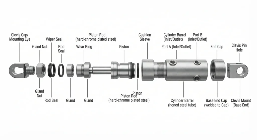
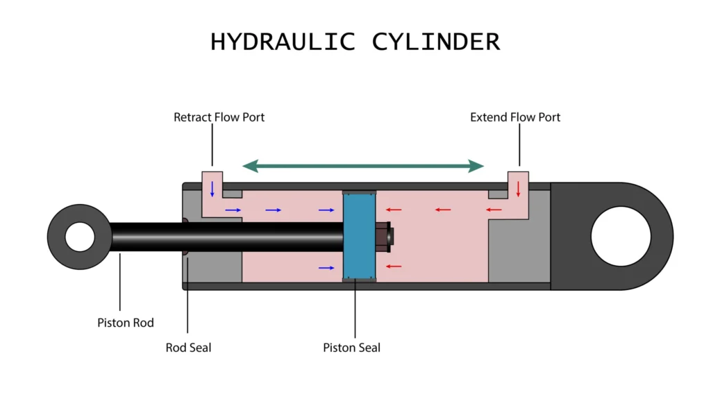
Stroke refers to the distance travelled by the piston rod as it moves from the retracted to the extended position; the piston is the component within the cylinder that receives hydraulic pressure and moves, whilst the piston rod transmits force and motion to the external load. End-of-stroke cushioning occurs when the piston approaches one end of its travel; as designed, it enters a deceleration zone to reduce its speed to a level suitable for reaching the end point.
For example, a horizontal material-feeding mechanism requires relatively rapid movement during the middle part of its stroke; however, maintaining the same speed whilst striking the end of the cylinder may result in noise, vibration and mechanical shock. Internal buffering can assist in deceleration as the piston approaches the end of its stroke, provided that the load, speed and energy remain within the permissible limits for that model. One should not assume that, simply because a cylinder has a buffering option, it can withstand high-speed movements to the end of its stroke under any circumstances.
You should first confirm whether the actual stopping position falls within the internal cushioning zone. If external fixtures obstruct the movement before the piston reaches the cushioning zone, the internal cushioning may not have time to take effect. When purchasing or modifying equipment, you may request that the supplier specify the cushioning start points and effective deceleration distances for both the extension and retraction strokes on the drawings, rather than simply noting ‘with cushioning’.
How a Cushion Spear and Restricted Flow Decelerate the Piston
① Follow the Oil as the Cushion Engages
A cushion piston is a protruding component that moves with the piston assembly and enters a mating bore as it approaches the end of its stroke; some ends utilise a cushion sleeve, the specific shape of which varies depending on the design. During the normal stroke, the oil to be discharged can flow through the normal passage towards the oil port; once the piston or sleeve enters the cushioning position, this high-flow passage is restricted, and the remaining oil must be discharged through smaller gaps, grooves or dedicated throttling passages.
Throttling involves restricting the flow of fluid through a smaller passage. As the fluid can no longer be discharged easily at its original flow rate, the pressure on the discharge side rises, generating a force opposite to the direction of motion, which causes the piston to decelerate. This pressure is also known as back pressure, i.e. the pressure generated by the resistance encountered by the fluid as it is discharged. During deceleration, the kinetic energy is primarily converted into heat through the restricted flow and transferred to the fluid and components.
The function of the piston is to gradually alter the discharge path; it does not stop the piston abruptly by direct impact, as a mechanical stop block would. For example, one design utilises segmented or tapered profiles to vary the flow area with position; another relies on a needle valve to regulate the bypass flow. A needle valve controls flow through a narrow opening between a fine valve spool and a valve seat; it must not be mistaken for a standard plug simply because of their visual similarity.
② Understand What Adjustment Can Change
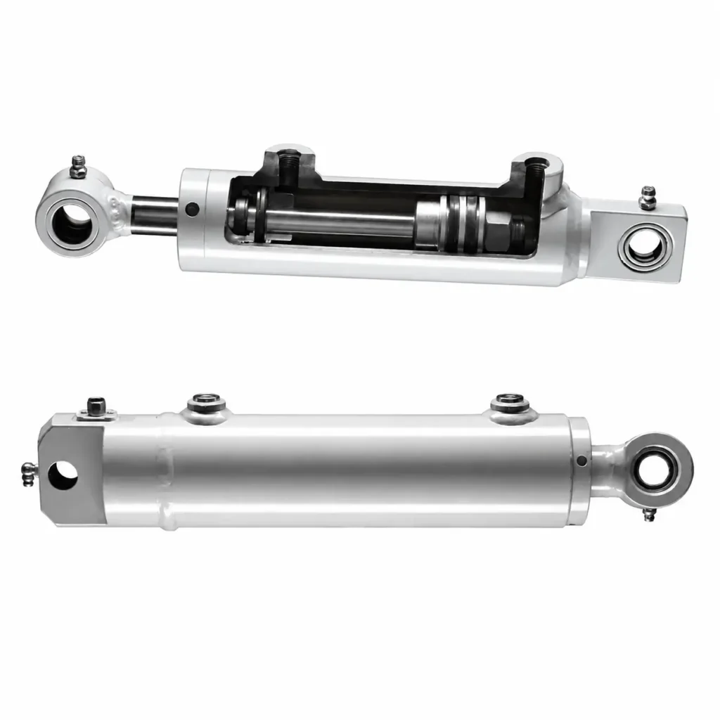
In structures where adjustment is permitted, altering the throttle opening typically changes the velocity and pressure behaviour within the buffer zone. If the opening is too large, the fluid is discharged more readily, and the deceleration effect may be insufficient; if the opening is too small, the end-of-stroke movement may be too slow, the pressure may be too high, or the stroke may not even be completed as required.
However, different designs may retain fixed passages or utilise piston clearance for fluid discharge; therefore, it cannot be universally stated that ‘a needle valve is guaranteed to lock when fully closed’, nor should the principle be that ‘the more it is closed, the better’. You should verify the permitted adjustment range for that specific model, as well as the cushioning capacity specifications provided by the manufacturer. Adjustment can only optimise performance within the existing structural capabilities; a cushioning device with insufficient energy absorption capacity cannot be ‘screwed’ into a larger specification.
③ Check How Reverse Flow Bypasses the Restriction
When the direction of movement reverses, the side that was previously discharging fluid must now receive fluid. If the fluid can still only pass through the narrow cushioning channel, the piston may move away from the end position very slowly. Consequently, many designs incorporate a one-way bypass, a floating sleeve or other rapid fluid inlet paths; a one-way bypass allows fluid to bypass the original throttling point under specified reverse conditions.
For example, if the cylinder is slow to start in the reverse direction after reaching the end, one cannot simply conclude that the cushioning is ‘set too tight’; one must also check the bypass structure, the control valve’s oil supply and mechanical resistance. When requesting a quotation, in addition to enquiring about the deceleration effect, one should also confirm the requirements for restarting from both ends, as smooth end-of-stroke positioning and timely departure from the end are two actions that must be coordinated.
Compare Fixed and Adjustable Cushion Designs
Fixed-type dampers achieve their deceleration characteristics through pre-designed orifices, grooves, clearances or contours; these are not typically altered on site by means of adjustment screws. They are suitable for confirmed loads, speeds and operating conditions, and help to minimise the risk of incorrect on-site adjustment; however, ‘fixed-type’ does not imply automatic adaptation to all operating conditions. There are also gradually variable damper designs that have been specifically calculated and require no on-site adjustment, though the application parameters must still be verified beforehand.
Adjustable buffers allow the throttling settings to be altered within a specified range and are suitable for scenarios where optimisation is required after installation, taking into account actual loads and cycle times. For example, where a single piece of equipment handles several known workpiece weights, an adjustable design may facilitate commissioning; however, it must be verified whether a single setting can cover all operating conditions, and operators must not be allowed to make arbitrary adjustments based on sound alone each time.
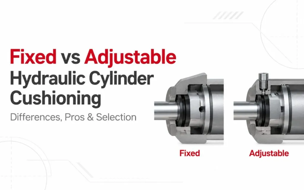
When making a selection, you should first list the lightest and heaviest moving masses, the lowest and highest entry speeds, as well as conditions for a cold machine and normal oil temperature. If operating conditions are relatively stable, a well-matched fixed-type solution may be considered; if variations are significant, adjustable, staged deceleration or other control solutions should be evaluated. Do not assume that adjustable types offer an unlimited range of adjustment, nor should you assume that fixed-type solutions are necessarily simple or of lower performance.
Calculate the Energy That Must Be Absorbed
1. Start with the Mass and Speed at Cushion Entry
Kinetic energy is the energy possessed by an object due to its motion; the fundamental calculation is Eₖ = ½mv². m is the equivalent moving mass that needs to be decelerated, and should take into account the load as well as the associated piston, rods, connecting components, etc.; v is the speed at the moment of entering the cushioning zone, which is not necessarily equal to the maximum speed reached during the journey. If the load is connected to the cylinder via a lever or rotary mechanism, the motion characteristics of the mechanism must also be factored into the analysis; the weight of the entire machine cannot simply be substituted directly.
Assuming an equivalent moving mass of 400 kg and an entry velocity of 0.5 m/s, the kinetic energy is 50 J. J stands for joules, the unit of energy. If the velocity increases to 1.0 m/s, the kinetic energy becomes 200 J. In other words, doubling the speed quadruples the kinetic energy; therefore, an end-of-stroke impact following an acceleration of the cycle is not necessarily caused by the sudden failure of the cushioning components.
These are theoretical examples and do not imply that any model permits entry into the cushioning zone at these speeds. You should use the equipment’s actual or verified entry speed and cross-check this against the manufacturer’s capacity data for that speed range.
2. Add Gravity and Continuing Drive Work
Kinetic energy is not always the only form of energy that must be accounted for. During downward motion, as the load continues to descend over the deceleration distance, gravity continues to perform work; during upward motion, gravity may assist in deceleration. If a hydraulic or other drive continues to drive the mechanism during deceleration, the work performed in this way must also be taken into account. Any other specified deceleration components that absorb part of the energy should also be distinguished in the complete energy balance.
Continuing with the assumptions of 400 kg and 0.5 m/s, and assuming an effective deceleration distance of 25 mm (i.e. 0.025 m) with a final velocity of zero, whilst disregarding friction and other energy pathways for the time being:
| Assumed motion conditions | Energy composition | Energy to be handled by the deceleration in this scenario |
|---|---|---|
| Horizontal motion, no sustained driving force | Kinetic energy upon entry | 50 J |
| Vertically downwards, no additional sustained driving force | 50 J + work done by gravity | Approx. 148.1 J |
| Vertically downwards, with an additional constant driving force of 4 kN in the same direction | 50 J + work done by gravity + work done by the driving force | Approx. 248.1 J |
In the table, the acceleration due to gravity is taken as g = 9.81 m/s²; the work done by gravity is mgs = 98.1 J; the 4 kN driving force performs work over a distance of 25 mm, amounting to 4,000 N × 0.025 m = 100 J. The conditions presented here serve to illustrate the sources of energy and do not constitute a conclusion for the selection of an actual hydraulic circuit. Calculations for industrial speed-reduction devices similarly verify kinetic energy, the work performed by the continuous driving force, and the energy load per unit time.
3. Use the Manufacturer Capacity Method Without Double Counting
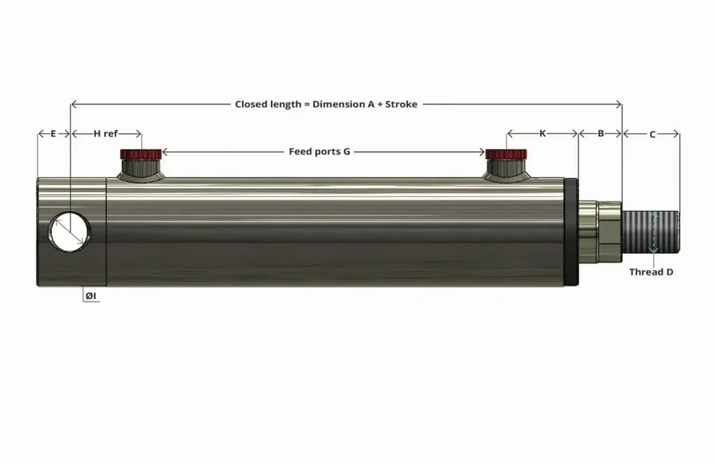
Tables or curves showing the buffering capacity of hydraulic cylinders may already have taken into account the drive pressure, cylinder bore, piston rod diameter, mounting orientation and permissible pressure; the cylinder bore refers to the internal diameter of the cylinder barrel, whilst the piston rod diameter refers to the diameter of the piston rod. Some specifications require the kinetic energy and gravitational terms to be calculated first, before consulting the capacity curve based on the working pressure; others utilise different characteristic parameters. You should adhere to a consistent methodology and must not mechanically repeat the inclusion of the same driving force in the results where the driving pressure has already been taken into account.
Furthermore, it is not sufficient for the energy per cycle to meet the requirements. For example, if the application changes from occasionally reaching the end of stroke to repeatedly doing so multiple times per minute, the sustained heating conditions faced by the hydraulic fluid and components will also change. When requesting a quotation, you should provide the operating frequency, dwell time and cooling conditions, rather than simply submitting a figure in joules.
Evaluate Load, Speed, Pressure, and Cushion Length
Effective deceleration distance and energy must be considered together. When the same amount of energy must be dissipated over a shorter distance, the average resistance required increases. Taking the simplified case where all the energy is dissipated by this deceleration process, the average resistance is approximately equal to the energy divided by the distance; however, the actual peak value also depends on the throttling profile and pressure variations, so the peak value cannot be verified using the average value as a substitute.
The buffering length is not equivalent to the total stroke, nor is it equivalent to the apparent remaining distance between the tooling and the mechanical stop. You need to confirm when the piston begins to restrict oil discharge, as well as how much of the effective buffering zone the equipment actually utilises. For example, if an external stop blocks the mechanism prematurely, or if the stroke is shortened so that the design buffering section is not fully entered, this will alter the performance. The pressurised areas, structures and capacities at both ends may differ; therefore, the extension and retraction should be verified separately.
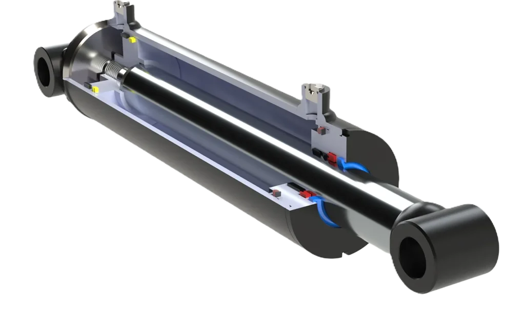
With regard to pressure, the buffer return chamber may develop localised pressures during deceleration that exceed those of normal return flow conditions; under certain conditions, these may even exceed the supply pressure. Whilst the main relief valve is designed to limit the pressure in the protective circuit, it does not automatically guarantee that high pressure will not occur in all spaces that are locally throttled or isolated by valves. You should ask the designer to confirm the permissible buffer pressure, the pressure-bearing capacity of relevant components and the measurement locations, and to provide details of the moving mass, entry speed, direction, supply pressure and hydraulic fluid conditions.
Adjust Cushioning Using the Manufacturer Procedure
Identify the Correct Adjuster and Starting Conditions
First, identify the adjustment mechanism by referring to the model number, drawings or manual. The small screws on the end cap may be used for cushioning, air bleeding or stroke adjustment respectively; they must not be used interchangeably. Cushioning adjustment typically alters the oil discharge characteristics and is not intended to change the output stroke arbitrarily; the air bleed screw, on the other hand, is used to bleed air in accordance with specifications.
Confirm the initial settings, adjustment direction, permissible range and whether adjustment requires depressurisation for this model. Factory settings may vary between products; therefore, a uniform approach such as ‘open fully first’ or ‘tighten fully then back off one turn’ cannot be applied. Some designs allow specific adjustment components to be closed at designated positions whilst still providing cushioning via other channels; whether this is permitted and how to close them must be determined by the relevant instructions. Do not apply force beyond the stop, nor unscrew the entire pressure-bearing assembly.
Tune in a Controlled, Repeatable Sequence
The following is a framework of the sequence to be covered during commissioning; specific pressures, speeds and operating conditions must still be carried out in accordance with the manufacturer’s procedures:
- Complete preparations. Secure any movable loads in accordance with the equipment procedures and ensure personnel are outside the range of motion; when it is necessary to approach or handle components, implement isolation measures to prevent accidental start-up and energy release, and verify the relevant pressure conditions.
- Check the hydraulic fluid and bleed the system. Confirm that the correct fluid is used, that the fluid level is adequate and the supply is normal, and carry out the necessary bleeding in accordance with approved methods to avoid mistaking instability caused by trapped air for a tuning issue.
- Conduct a test run under specified conditions. Start from a permitted commissioning state and observe the speed before and after entering the buffer zone, end-of-stroke behaviour, pressure and cycle time; do not test by striking the end of the stroke at high speed with the maximum load.
- Adjust one variable at a time. Within the limits permitted by the manual, make small adjustments to the specified settings, record the changes relative to the baseline, and then compare under the same conditions. Do not alter speed, load and cushioning settings simultaneously.
- Verify full stroke and reverse start-up. Confirm that the required position is reached without any abnormal hard impacts or pressure anomalies, then check that restarting from that end is normal.
- Verify the actual operating range. Cover the specified load, speed and oil temperature conditions in accordance with the approved procedure, and reset safety guards, secure adjustment components and retain records as required.
If the manual requires depressurisation prior to adjustment, the corresponding shutdown and verification procedures must be completed before each adjustment; if a specific method of in-service adjustment is explicitly permitted, the designated positions, tools and safety precautions must also be observed. General adjustment guidelines must not be treated as authorisation for pressurised operation of a specific model.
Aim for Smooth Arrival, Not the Strongest Restriction
A suitable setting should allow the cylinder to reach the required end position smoothly within the permitted pressure and cycle time, whilst meeting subsequent reverse start-up requirements. Complete silence is not the sole criterion, nor should the impression that it ‘sounds too light’ be used as a substitute for pressure and position checks. The operating instructions describe the buffer adjustment objective as completing the stroke whilst avoiding heavy impacts against the cylinder end; this is more practical than simply pursuing stronger throttling.
For example, if the cylinder appears to operate smoothly under no-load conditions but still slams against the end stop when switched to the specified load, the energy and capacity ranges should be re-evaluated rather than simply tightening the adjustment mechanism indefinitely. Where there is a marked difference in performance between a cold and a warm cylinder, checks should also be carried out in conjunction with the hydraulic fluid and actual temperature, to prevent operators from masking underlying issues through frequent compensatory adjustments.
Diagnose End Impact, Slow Reversal, and Excessive Pressure
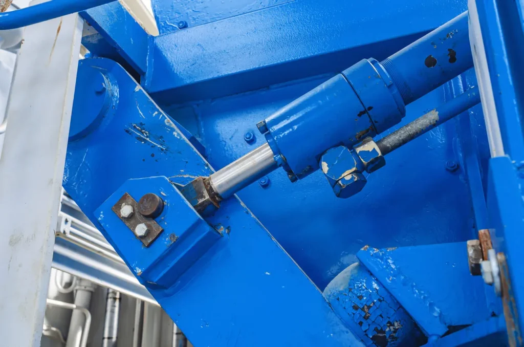
① Locate the Event Before Choosing a Cause
First, note whether the anomaly occurs during extension or retraction, and whether it happens before or after entering the buffer zone. Also, check whether the issue is consistent under cold-start, warm-start and different load conditions. Do not assume that the buffer needle valve is open too wide simply because of a ‘bang’—the noise may also originate from the external limit stop, pin clearance or the mounting structure.
| Symptom | Possible areas to check | Practical first step |
|---|---|---|
| Obvious hard impact at end stop | Excessive entry speed or energy, incorrect settings, worn buffer components or failure to enter the buffer zone | Check the actual stopping position, entry speed and buffering capacity at that end |
| Excessively slow final section or failure to reach the required position | Excessive throttling, changes in oil temperature and viscosity, insufficient oil supply or mechanical jamming | Confirm whether the cylinder has actually entered the cushioning zone, then verify the settings and pressure |
| Delayed reverse start from the end | Obstruction of the reverse bypass, insufficient valve oil supply, static friction or mechanical load | Check the reverse oil supply path and control conditions for this model |
| Abnormal pressure peaks during deceleration | Insufficient deceleration distance, excessive input energy, channel abnormalities or the influence of sustained driving force | Record dynamic pressure and input velocity at the specified position |
| Inconsistent performance | Air ingress, contamination, load or oil supply variations, fit and mounting issues | First establish repeatable operating conditions; do not rush to repeatedly adjust the needle valve |
Viscosity refers to the ‘thickness’ of the oil as it flows, which affects the resistance encountered when passing through small passages; however, it is not the sole cause of deceleration in the final stage. The table lists troubleshooting directions; it does not provide a definitive repair conclusion based solely on observed phenomena.
② Measure the Cushion Event, Not Only Pump Pressure
Transient pressure peaks may not be clearly visible on a standard pressure gauge, and pump outlet readings do not necessarily represent the pressure in the cushion chamber. When measurements are required, they should be carried out by competent personnel using appropriate measurement points and instruments, and analysed in conjunction with rod position, entry speed and supply/return oil conditions; do not loosen fittings to attach a pressure gauge whilst the equipment is running, nor check for pressurised leaks by hand.
For example, the absence of a noticeable change in pump pressure whilst end-of-stroke impact persists does not prove that there is no high pressure in the cushion chamber; conversely, sluggish reverse movement does not prove that the cushioning effect is too strong—it may be a problem with the bypass structure or control valve. Where damage to the buffer piston, sleeve, passageways or seals used to restrict oil leakage is suspected, the machine must be shut down and inspected in accordance with procedures; the equipment must not be allowed to continue repeatedly striking the end stops to collect ‘further samples’.
③ Stop When Adjustment Cannot Restore the Required Behavior

In the event of abnormal surging, persistent hard impacts, failure to complete the specified stroke, pressure exceeding limits or new instances of oil spray or leakage, commissioning must be halted and the cause addressed. Do not increase the relief valve setting to force the cylinder through the buffering section, nor turn the adjustment screw beyond the permitted range to accelerate the return from the end position.
If the settings are already within the permitted range but the actual operating conditions still exceed the energy, speed or pressure capacity at that end, it will be necessary to select a different buffering mechanism or an external deceleration solution. The basis for this judgement should be records of position, pressure, speed and time under specified conditions, rather than the number of turns the adjustment screw has been turned.
Choose Internal Cushions or External Deceleration

Internal buffering is suitable for movements where the actuator actually reaches the buffer zone within the cylinder and where the energy and frequency fall within the confirmed capacity range. For example, in a linear reciprocating mechanism with fixed end points, internal buffering can be evaluated to reduce end-of-stroke impact; however, it cannot, by default, handle stops at arbitrary intermediate positions or external collisions occurring throughout the entire stroke.
If a longer deceleration distance, multiple stops or a more refined speed profile is required, external flow control, deceleration control with position feedback, or independent industrial buffers may be considered. Position feedback involves a sensor transmitting the actual position back to the control system, enabling motion commands to be adjusted according to position; independent buffers, on the other hand, require suitable mechanical contact and load-bearing paths. For example, if a slide table must stop before the hydraulic cylinder enters the internal buffer zone, external solutions are generally worth considering; however, the load, speed, stopping distance and cycle frequency must still be verified.
The two approaches can also be combined; for instance, external control can first reduce the approach speed, followed by the internal buffer handling the remaining end-of-stroke energy. However, a comprehensive energy and pressure verification must still be carried out after combination; the energy-absorption values listed in the catalogues of individual components cannot simply be added together. When submitting requirements to GY Hydraulic, it is recommended to provide the moving mass, entry speed, installation orientation, actual stopping position, cycle frequency and parameters of existing pumps and valves, before confirming whether to adopt a single-end, double-end, fixed, adjustable or solution incorporating external deceleration.
FAQs
Is a cushioned cylinder the same as a shock absorber?
No. A cushioned hydraulic cylinder is primarily an actuator that generates push-pull motion, with internal cushioning helping it to decelerate at the specified end of its stroke; a standalone industrial shock absorber is primarily designed to absorb external kinetic energy and requires separate installation and matching. Whilst both may utilise restricted oil flow to dissipate energy, they are not directly interchangeable. For example, if an external slide strikes a limit stop midway through the cylinder’s stroke, one cannot expect the internal cushioning—which has not yet entered the working zone—to provide the same level of protection.
Do cushions act throughout the entire stroke?
Common end-of-stroke cushioning primarily operates within a range near the designed end point; it is not a speed-control device for the entire stroke. For example, if a low speed is required during the middle of the working stroke, this should be achieved through appropriate flow control or motion control. You should confirm the starting point of the cushioning in the drawings; if the speed slows abnormally throughout the entire stroke, you should also check the oil supply, valves and mechanical resistance, as this cannot be attributed solely to the cushioning.
Can cushioning be provided at both ends?
Yes, some models offer the option of cushioning at the extension end, the retraction end, or both ends; however, the corresponding structure and capacity must be verified separately. The effective area, load direction and entry speed may differ at each end, so the same settings cannot be applied by default. For example, where the extension stroke is unloaded whilst the retraction stroke carries a heavy load, both ends should be calculated based on their respective actual operating conditions; they should not be assumed to be matched simply because ‘double-end cushioning’ is specified.
Does cushioning reduce the rated static cylinder force?
Generally, the theoretical static force corresponding to the cylinder bore and rod diameter will not change merely due to the addition of a cushioning option; however, specific rated values should still be confirmed against the model’s technical data. The actual net force also depends on the pressures in both chambers and the effective area; the back pressure built up during cushioning deceleration will affect the output at that moment. You should distinguish between static ratings and the instantaneous forces during the cushioning process; a reduction in speed or output limitation upon entering the cushioning zone should not be taken directly as proof that the cylinder bore has been incorrectly selected.
Can cushioning compensate for an undersized cylinder?
No. Cushioning does not provide additional sustained thrust, nor can it correct issues relating to pressure-bearing capacity, rod stability or insufficient flow rate. For example, if the cylinder is unable to move the load partway through its stroke, this cannot usually be resolved by adjusting the end-of-stroke needle valve; similarly, if the cushioning mechanism itself lacks sufficient energy-absorption capacity, this cannot be infinitely increased by tightening the adjustment mechanism. You should verify the selection of the basic cylinder and the cushioning system separately to first determine which component is at fault.
Can oil temperature affect cushioning behavior?
Yes. Oil temperature alters viscosity and may also affect leakage, seal friction and valve performance; therefore, the same settings may not yield identical results in a cold versus a warm system. For example, if the final stroke is sluggish during a cold start and impact becomes more pronounced as the system warms up, you should verify the actual oil temperature, the specified oil grade and the operating range, rather than immediately switching to a thicker oil. You should complete commissioning under the temperature conditions specified by the manufacturer and verify the permissible cold and hot operating conditions.
Can a cylinder be retrofitted with internal cushions?
For some models, this can be achieved using approved components or through redesign; however, simply drilling a hole in the end cap and adding a needle valve does not constitute a complete retrofit. This may involve the piston rod, end caps, cushion sleeves, internal passages, effective stroke and pressure-bearing structures. For example, after replacing a component at one end, the installation dimensions and reverse start-up conditions must also be verified. The manufacturer should first review the original cylinder drawings before confirming the modification plan, calculations and acceptance criteria.
Does cushioning replace a load-holding valve?
No. End-of-stroke cushioning is used to decelerate motion, whilst a load-holding valve is used to restrict hydraulic fluid flow to a designed limit; their functions are distinct. For example, when a vertical load comes to rest midway through its stroke, end-of-stroke cushioning typically has not yet taken effect; even when the end of stroke is reached, the throttling passage must not be regarded as a reliable load-holding device. You should verify the requirements for static load-holding, pressure-loss response and maintenance support separately; the presence of cushioning must not be used as a reason to omit the required load-holding function.
Choosing a Trusted Hydraulic Cylinder Manufacturer
From standard hydraulic cylinders to custom solutions, we help you improve equipment performance, delivery reliability, and batch consistency
Explore Rivmate Cases

Hey There, I'm Melody!
We are a hydraulic cylinder manufacturer. For over 20 years, we have focused on producing reliable hydraulic cylinders. Need a hydraulic cylinder solution? Feel free to contact us.