Home / How Does a Single Acting Hydraulic Cylinder Work? Guide
How Does a Single Acting Hydraulic Cylinder Work?
- Author: GY Hydraulic
- 20+ Years of Manufacturing
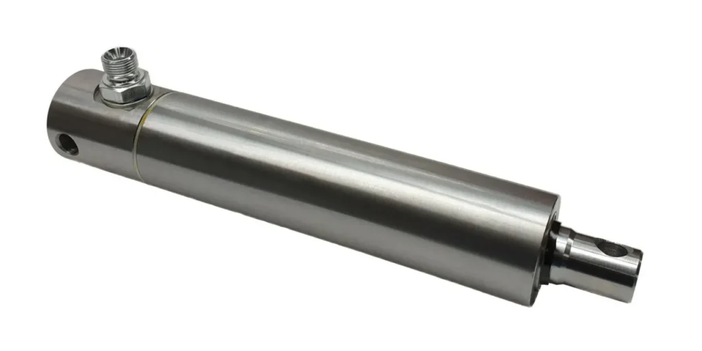
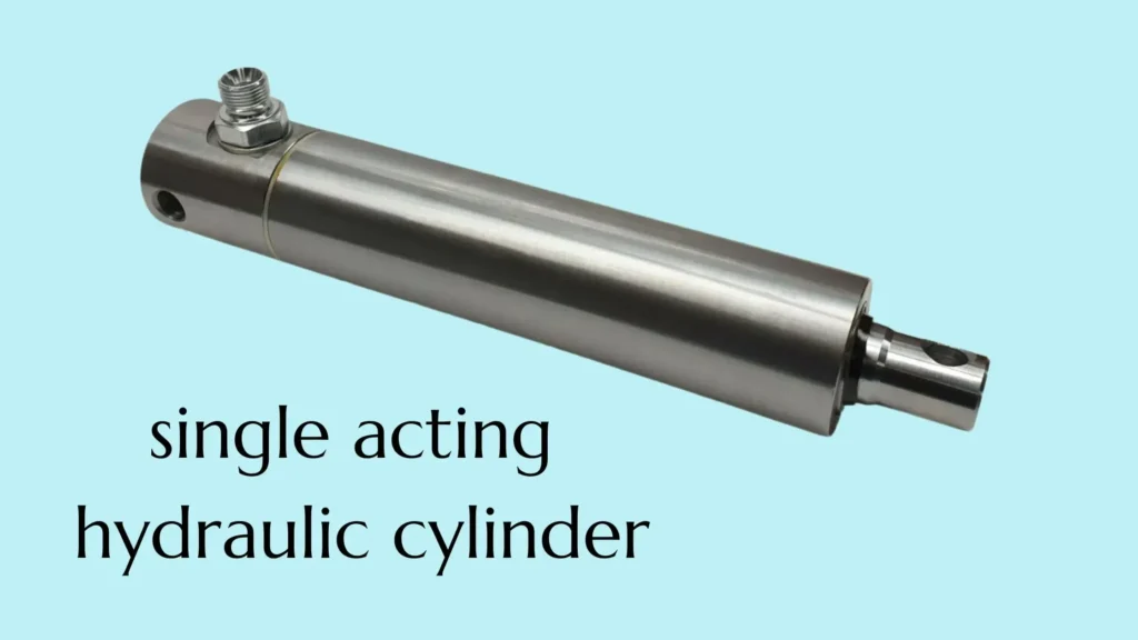
A single-acting hydraulic cylinder uses hydraulic oil pressure to drive the piston or plunger in one direction, converting hydraulic energy into linear thrust. Movement in the opposite direction is achieved by a spring, the weight of the load, or an external mechanical force. In a typical hydraulic extension design, pressurized fluid enters the working chamber, pushing the piston rod outward. When the control valve opens the return line, the return force pushes the piston rod back, and the hydraulic fluid is drained back to the reservoir.
You can think of this process as “hydraulic power drives extension, while external force drives retraction.” However, stopping the fluid supply does not necessarily mean the cylinder will automatically retract. The retraction force must be sufficient to overcome friction and return flow resistance, and the hydraulic fluid must have an unobstructed return path. Understanding this can help you determine why equipment lifts smoothly but may experience slow descent or failure to retract.
In this GY Hydraulic guide, you’ll learn about the main components of a single-acting hydraulic cylinder, the fluid inlet and return processes, and the conditions under which different retraction methods are appropriate.
Table of Contents
How Does a Single Acting Hydraulic Cylinder Work?
A single-acting hydraulic cylinder is driven by hydraulic oil pressure in only one direction. Movement in the opposite direction is achieved by a spring, the weight of the load, or an external mechanical force. For the common “hydraulic extension, external force retraction” design, the operating process is as follows: pressurized oil enters the cylinder, pushing the piston rod to extend; the control valve then opens the return line, and the return force pushes the piston rod back, returning the oil to the reservoir. Based on this design, it should be noted that for some single-acting cylinders, the hydraulic drive direction can also be retraction.
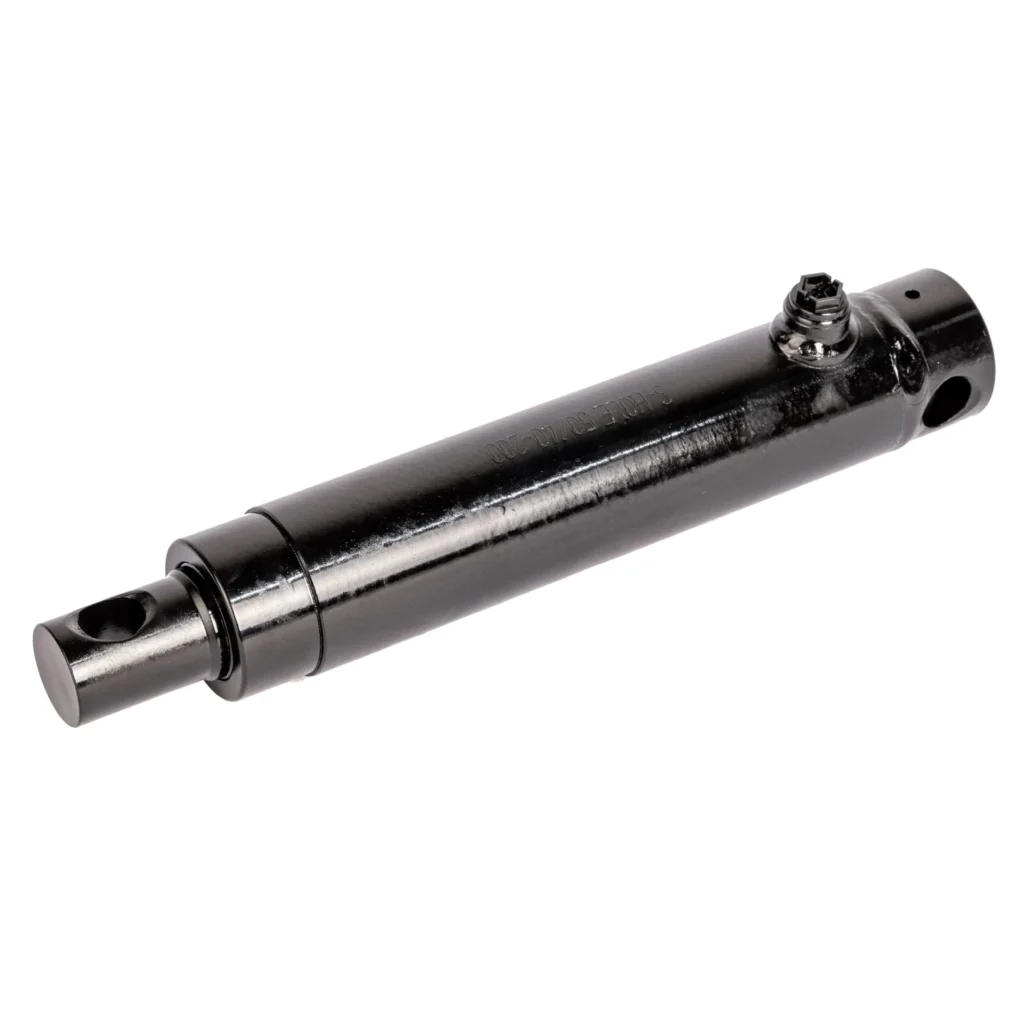
Pressurized Oil Enters the Single Port
Single-acting hydraulic cylinders typically have only one working port for both oil inlet and return. During extension, the hydraulic pump delivers oil through the control valve into the working chamber—the space inside the cylinder that holds the pressurized oil. As the fluid enters, the pressure rises. When the hydraulic pressure is sufficient to overcome the load, seal friction, and other resistances, the piston begins to move, causing the piston rod to extend. During retraction, the fluid flows out through the same working port.
For example, in a dump truck equipped with a single-acting lifting cylinder, the hydraulic fluid entering the cylinder drives the lifting mechanism to raise the truck bed. You need to distinguish between pressure and flow rate: Pressure determines how much force the cylinder can generate, while flow rate primarily determines how quickly it extends. If the cylinder can move the load but the action is too slow, you should verify the actual supply flow rate and check for line restrictions; the problem cannot be solved simply by increasing the pressure.
Pressure Acting on Piston Area Creates Extension Force
The pressure of the hydraulic fluid acts on the effective area of the piston, generating an extension force. The “effective area” refers to the area under pressure that contributes to the hydraulic force. For common rodless designs with oil entering the chamber, it is typically equal to the full cross-sectional area of the piston, which can be calculated based on the cylinder bore diameter. Plunger-type cylinders do not have the same independent piston structure; therefore, the effective area under pressure should be calculated based on the plunger.
You can use the theoretical extension force F = pressure P × effective area A to make a preliminary assessment. For example, assuming a piston diameter of 50 mm and a working chamber pressure of 10 MPa, the effective area is approximately 1,963 mm². Since 1 MPa equals 1 N/mm², the theoretical thrust is approximately 19,630 N, or 19.6 kN. The actual available thrust must account for friction; designs with spring-return mechanisms must also account for spring resistance.
When selecting a cylinder, you should first confirm the thrust required by the equipment, then determine the effective area based on the allowable operating pressure. A common mistake is to calculate the extension force of a standard piston-type hydraulic cylinder using the piston rod diameter. For rodless chamber oil inlet configurations, the cylinder bore diameter should be used. If the cylinder lifts a car body via a connecting rod, the required thrust must be calculated based on the mechanical leverage ratio; the weight of the car body cannot be directly treated as the cylinder’s load.
Releasing Pressure Opens the Return Path
Strictly speaking, a drop in pressure alone does not automatically open the return path. You must use a control valve or relief valve to connect the cylinder’s working chamber to the reservoir. The return force then pushes the piston, and the fluid is drained back to the reservoir through the working port and return line. Stopping the hydraulic pump merely stops the oil supply; if the valve still blocks the port, the fluid remains trapped in the working chamber, and the piston rod cannot retract normally.
You can use a manual hydraulic jack as an example to understand this process: when you operate the handle, fluid enters the cylinder and lifts the load; after opening the return valve, the load pushes the piston down, and the fluid flows back to the reservoir. The descent speed depends on the return force and the restrictions of the return path; therefore, when lowering a load, you need to use descent control measures appropriate for the load to prevent a rapid drop caused by suddenly opening the return path.
If your cylinder extends normally but retracts slowly or does not move at all, you should first ensure the load is securely supported, then verify that the valve is in the return position, and finally check whether the quick-connect fittings are properly connected and whether the lines are obstructed. Return flow resistance creates “back pressure,” which is the pressure that hinders the oil from draining out. For spring-return cylinders with low return force, even slight back pressure can significantly affect retraction. Do not drain oil or diagnose faults by loosening pressurized fittings.
A Spring, Gravity, or the Load Retracts the Rod
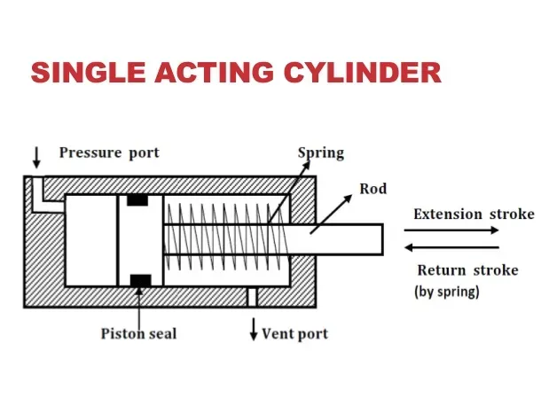
Once the return line is open, the cylinder still requires a reliable retraction force. In a spring-return cylinder, the internal spring is compressed during hydraulic extension, and the spring pushes the piston rod back during retraction. For example, some short-stroke clamping devices may use this design. However, spring return does not guarantee rapid retraction in every installation scenario; the retraction speed is still affected by spring force, friction, and return flow resistance.
Gravity- or load-return mechanisms utilize the equipment’s own weight or a force applied by an external mechanism to achieve retraction. For example, a car equipped with a single-acting lifting cylinder can descend under its own weight. However, it is not sufficient to simply confirm that “the equipment is heavy.” The key is whether this weight can, through the mechanism, continuously provide sufficient retraction force to the cylinder throughout the entire stroke. Installation orientation, mechanical angles, and load variations can all affect the reliability of the return motion.
For car lifting mechanisms, verify both the no-load condition and the entire lowering stroke; for horizontally mounted mechanisms, confirm that springs or external mechanisms can provide the retraction force. If the equipment needs to retract actively without an external retraction force, or if it must still pull the load during retraction, a double-acting hydraulic cylinder should be considered. A double-acting design provides hydraulic power in both the extension and retraction directions.
Which Components Control the Operating Cycle?
The operating cycle of a single-acting hydraulic cylinder is carried out by several sets of components working together: the cylinder barrel, piston, and piston rod convert hydraulic pressure into motion; seals and guide elements help maintain stable motion; directional control valves determine when fluid enters or exits; and springs or external loads provide the return force. You can understand their functions by following this sequence: “fluid inlet—extension—hold—fluid outlet—retraction.” The following example illustrates a common design featuring hydraulic extension and external force retraction.
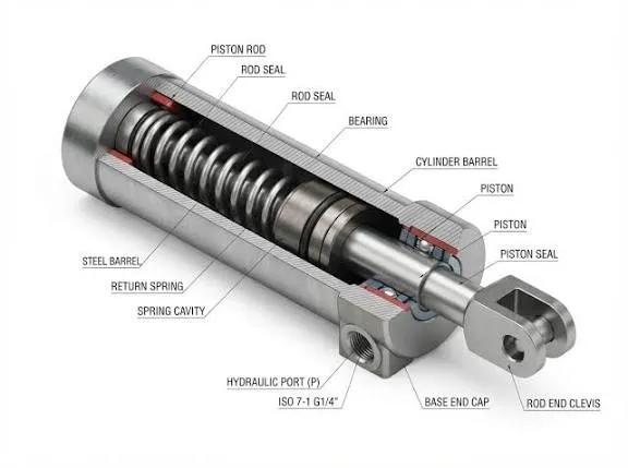
Cylinder Barrel, Piston, and Piston Rod
The cylinder barrel is the cylindrical housing that contains pressurized fluid and guides the piston’s movement. The piston, located inside the cylinder barrel, converts fluid pressure into thrust; the piston rod connects the piston to the external mechanism, transmitting this thrust to the equipment. In standard piston-type hydraulic cylinders, piston seals also prevent fluid from leaking from the pressurized side to the other side. Note that single-acting plunger cylinders have a different structure; they may not have a separate piston, and hydraulic pressure acts directly on the effective area of the plunger.
For example, when a hydraulic cylinder pushes a lifting link, the piston rod extends outward, causing the link to rotate. Here, the cylinder bore diameter affects the theoretical thrust at a given pressure, the stroke determines how far the rod can extend, and the dimensions and extension length of the piston rod relate to its stability under load. You cannot select a hydraulic cylinder based solely on thrust; you must also provide the supplier with the stroke, mounting method, and maximum extension condition so they can verify the piston rod’s buckling resistance—that is, its ability to resist bending instability under load.
A practical rule of thumb is: The piston rod should push and pull along its own axis, while the external mechanism should be responsible for guiding the load. If the mechanism pulls the piston rod sideways during motion, even with sufficient thrust, increased friction, localized wear, or sticking may occur. Do not use the piston rod as a guide rail to bear lateral loads.
Rod Seal, Wiper, and Guide Elements
These three types of components are all located near the moving surfaces but serve different functions. The rod seal primarily prevents hydraulic fluid from leaking outward along the piston rod; the dust seal scrapes away dust and debris from the surface as the piston rod retracts, reducing the entry of contaminants into the cylinder; guide elements typically include guide sleeves or wear rings, which support the piston rod and piston, minimizing misalignment and direct metal-to-metal contact. Seals are responsible for controlling leakage, while guide elements are responsible for support; seals should not be tasked with guiding functions.
For example, the piston rod in outdoor equipment may come into contact with mud and sand. If the dust seal is damaged, contaminants are more likely to enter the interior during the retraction stroke, causing wear on the seals and moving surfaces. For spring-return cylinders, seal friction can also affect retraction: the sealing system must simultaneously meet the requirements for leak prevention and low friction; a tighter fit is not necessarily better. When selecting a cylinder, you should specify the fluid type, temperature, operating speed, and contamination environment so that the supplier can match the appropriate seal material and design.
During routine inspections, check the piston rod for persistent oil leakage, longitudinal scratches, or one-sided wear. Persistent oil leakage requires investigation, but a thin lubricating oil film should not be immediately interpreted as seal failure. If scratches or wear are concentrated on one side, also inspect the alignment and guidance conditions; simply replacing the seals may not eliminate the root cause.
Single Hydraulic Port and Directional Control Valve
Single-acting cylinders typically use the same working port for both oil inlet and return. A directional control valve, also known as a spool valve, is responsible for changing the connections in these oil circuits: during extension, it connects the oil supply line to the cylinder; during retraction, it connects the cylinder to the tank. If position holding is required, the valve must also seal the cylinder passage in the corresponding position. Some piston-type designs also feature a vent port, which is used for venting the non-pressurized chamber and is not a second hydraulic drive port.
For example, a common three-way, three-position valve can provide three control positions: extension, hold, and retraction. “Three-way” refers to the three main ports: pressure port P, tank port T, and cylinder port A; “three-position” refers to the spool having three operational positions. However, the specific functionality still depends on the valve’s hydraulic circuit design; one cannot assume solely based on the name that the middle position will necessarily hold the cylinder in place. When selecting a valve, verify the hydraulic symbols and the communication relationships between each position.
If retraction is slow, check whether the valve has fully opened the return path and whether quick-connect fittings, hoses, or return lines are creating restrictions. Although the cylinder has only one port, any restriction connected to its exterior may affect the entire cycle. Additionally, directional control valves primarily determine the direction of fluid flow; when stable control of the load lowering speed or reliable load holding is required, corresponding flow control and load-holding measures must also be implemented—ordinary directional control valves should not be treated as permanent supports.
Return Spring or External Return Load
For single-acting hydraulic extension cylinders, opening the return line merely allows fluid to flow out; what actually drives the piston rod to retract is the return spring or an external return load. A spring-return mechanism stores spring energy during extension and releases this force during retraction; a load-return mechanism relies on the weight of the equipment or the retraction force applied by an external mechanism. Both methods must overcome seal friction, mechanical resistance, and return backpressure.
For example, a short-stroke clamping mechanism can use a spring-return design, but it must be confirmed that the spring can overcome resistance throughout the entire return stroke. Lifting mechanisms may utilize their own weight for retraction, but the actual retraction force acting on the cylinder will change as the mechanical angle changes. Therefore, the presence of a heavy load does not guarantee reliable retraction; similarly, a cylinder installed horizontally without a spring or external retraction mechanism cannot be expected to retract automatically under gravity.
You can use “minimum retraction force” as a selection criterion. Provide the supplier with the lightest load, the mechanism angle over the entire stroke, the installation orientation, and the allowable retraction time to verify whether there is still sufficient retraction force under the most unfavorable conditions. For spring-return cylinders, you should also verify how the spring force varies with stroke. If the equipment must actively pull the load back and there is no reliable external retraction force available on-site, you should consider a double-acting design capable of providing hydraulic retraction power.
What Changes Between Spring-, Gravity-, and Load-Return Designs?
The main difference among the three designs lies in the source of the return force: spring-return relies on spring force, gravity-return relies on the weight of the moving parts or equipment, and load-return relies on the force provided by an external load or mechanism. In all three cases, the return oil passage must first be opened to allow the piston rod to retract. The return force must also overcome seal friction, mechanical resistance, and return oil back pressure—that is, the resistance encountered when the hydraulic fluid is returned to the reservoir.
It is important to note that gravity return and load return are not entirely distinct categories. When an external load pushes the cylinder to retract using its own weight, both terms describe the same return mechanism. Therefore, when selecting a cylinder, do not rely solely on the product name; you must also confirm exactly what provides the return force and whether that force is reliable throughout the entire stroke.
Spring-Return Cylinders
Spring-return hydraulic cylinders use a spring to push the piston rod back to its home position. In a common hydraulic extension design, pressurized fluid compresses the spring as it pushes the piston; when the return line opens, the spring releases its stored energy, pushing the piston rod back and expelling the fluid. The advantage of this design is that it provides its own return force and does not rely entirely on the external load.
For example, a short-stroke clamping fixture that clamps during extension and releases during retraction can utilize a spring-return structure. However, the spring requires installation space and consumes a portion of the hydraulic thrust during extension. Longer strokes typically increase the difficulty of spring placement, so this type of design is commonly used in scenarios such as short-stroke clamping; however, it would be incorrect to simply assume that all long-stroke cylinders are unsuitable for spring-return mechanisms.
When selecting a model, you should ask the supplier to verify the spring force across the entire stroke, especially the available return force near full retraction. With common compression springs, the spring force decreases as the spring is gradually released. If the return force is insufficient in the final stage, the cylinder may retract normally during the first half of the stroke but stop during the last segment. You should also specify the weight of the connected components, the installation orientation, and the allowable retraction time. Do not assume that “a spring will always ensure rapid reset,” and do not directly disassemble the spring chamber, as the internal preloaded spring may still store energy.
Gravity-Return Cylinders
Gravity-return hydraulic cylinders rely on the weight of the moving parts or the equipment itself to retract. For example, in a vehicle equipped with a single-acting lifting cylinder, once the return line is opened, the vehicle can descend under its own weight, thereby pushing the cylinder to retract. In this case, the force of gravity must be converted into a force acting in the direction of cylinder retraction through the mounting orientation or a link mechanism. The cylinder does not necessarily need to be mounted vertically, but the mechanism must be capable of effectively transmitting this force.
This design is suitable for mechanisms where reliable gravity return conditions are consistently available. It typically does not require an internal return spring, but the return capability is affected by the weight of the equipment, the angle of the mechanism, and friction. If you modify a cylinder that originally relied on gravity for retraction to a horizontal push-pull configuration, or change its mounting orientation, you must re-evaluate the return conditions.
When determining suitability, check the entire lowering stroke under the lightest load. For example, with a dump truck, you must not only confirm that the fully loaded body can lower but also verify that there is still sufficient return force as the empty body approaches its final position. A common mistake is to consider only the total weight of the equipment while ignoring changes in the link angle. Another mistake is to treat gravity return as free fall; lowering under load still requires proper return flow control and load-holding measures.
Load-Return Cylinders
In a load-return hydraulic cylinder, the piston rod is retracted by an external load or mechanical mechanism. It typically lacks an internal return spring, so the return force must be provided by the equipment. If this force comes from the weight of the load, it is also considered a gravity-return system; if it comes from a separate return mechanism, the actual retraction force that mechanism can provide must be verified.
For example, when a load-return cylinder is used to lift a heavy object, the object can push the piston rod back during a controlled descent. However, once the object is removed, the cylinder may not return to its starting position on its own. The Enerpac HCG Series manual explicitly states that this series employs hydraulic extension and load-return operation; when unloaded, an external manual force is required to retract the piston. This is a product specification for this series and should not be directly applied as an operating method for all cylinders.
When selecting a cylinder, you should confirm whether the load is continuously applied throughout the entire return stroke, rather than only at the start of retraction. If the equipment disengages from the load after retracting to a certain position, the remaining stroke may not be completed. Therefore, you should provide the supplier with information on the minimum return load, contact conditions, mechanical angles, and friction conditions. For equipment that frequently resets under no-load conditions and requires the load to be actively pulled back, relying solely on load-return is generally unsuitable; spring-assisted or hydraulic retraction solutions should be considered.
How Are Force, Speed, and Return Time Determined?
The theoretical extension force of a single-acting hydraulic cylinder is determined by the pressure and the effective pressure area, while the extension speed is primarily determined by the actual oil flow rate and the effective area. The return time, however, depends on the combined effect of the return force and the return flow resistance and cannot be directly calculated using the oil supply flow rate of the hydraulic pump. The following example uses a single-stage, hydraulically extended cylinder; for multi-stage telescoping cylinders, calculations must be performed separately for the effective areas of each stage.
Extension Force: Pressure Multiplied by Effective Area
The basic formula for theoretical extension force is F = P × A. Here, F is the hydraulic force, P is the pressure in the cylinder’s working chamber, and A is the effective area under pressure—that is, the area actually involved in generating thrust. For standard piston-type cylinders with oil entering the rodless chamber, the effective area is typically calculated based on the cylinder bore: A = πD² ÷ 4. For plunger-type cylinders, however, the effective area under pressure must be calculated based on the plunger itself; the cylinder bore diameter cannot be used universally.
For example, assuming a cylinder bore of 50 mm and a working chamber pressure of 10 MPa, the effective area is approximately 1,963 mm². Since 1 MPa equals 1 N/mm², the theoretical extension force is approximately 19.6 kN. However, this is not the net thrust ultimately obtained by the equipment. Sealing friction consumes a portion of the force, and the spring-return mechanism must also overcome spring resistance. If the cylinder drives the load via a connecting rod, the actual force transmitted to the load will also vary with the angle of the mechanism.
When performing calculations, you should use the actual pressure in the cylinder’s working chamber rather than the hydraulic pump’s rated pressure directly. Pressure losses occur in piping and valves, so the pump outlet pressure may not necessarily equal the cylinder inlet pressure. When selecting a cylinder, you should not simply choose one where the theoretical thrust exactly matches the load requirement; instead, you should verify the available thrust by considering startup resistance, load variations, and the installation configuration, while adhering to the rated pressure limits of the cylinder and circuit components.
Extension Speed: Flow Divided by Piston Area
Under simplified conditions—ignoring leakage, fluid compression, and the startup process—the extension speed can be calculated as v = Q ÷ A. Here, v is the piston’s speed, Q is the actual flow rate entering the working chamber, and A is the effective area. You can think of it this way: for every unit of distance traveled, the cylinder must be filled with a corresponding volume of fluid; at a given flow rate, the larger the effective area, the slower the movement speed.
Let’s continue with the example of a 50 mm bore cylinder. Suppose the actual inflow rate is 6 L/min, which converts to 100,000 mm³/s. Dividing this by 1,963 mm² yields a theoretical extension speed of approximately 51 mm/s. If the stroke is 200 mm, the extension time is approximately 3.9 seconds when calculated at a constant speed. Actual operation may also be affected by valve opening processes, leakage, and flow rate variations; therefore, this result is suitable for preliminary estimation but cannot be directly used as a guaranteed value for the equipment.
When selecting the cylinder bore, both thrust and speed should be verified. Increasing the cylinder bore can increase the theoretical thrust at the same pressure, but it will also reduce the extension speed if the oil supply flow rate remains constant. If the equipment has sufficient thrust but operates too slowly, check the actual flow rate entering the cylinder, the valve’s flow capacity, and pipeline restrictions, rather than simply increasing the pressure. Higher pressure does not necessarily result in increased speed.
Spring Force and Load Weight During Retraction
When a single-acting hydraulic cylinder retracts, a spring or external load must provide sufficient retraction force. For typical retraction processes, a simplified relationship can be used to determine this: **The retraction driving force must exceed the sum of mechanical friction, external resistance, and resistance caused by return oil back pressure. ** The resistance to retraction caused by back pressure can be estimated as F_(back pressure) = P_(back pressure) × A, where A should be the effective area of the return chamber for that specific configuration.
The retraction force of a spring-return cylinder typically varies with position. In common compression springs, the spring is further compressed as the piston rod extends and is gradually released during retraction, causing the spring force to decrease accordingly. Therefore, you may observe that the cylinder retracts more quickly in the initial portion of the stroke and slows down as it approaches the end. When selecting a cylinder, verify the spring force over the entire stroke—particularly the available retraction force in the final segment—rather than just the maximum force when the spring is fully compressed.
The return force for a loaded cylinder cannot be determined by weight alone. For example, assume a 100 kg load directly pushes the cylinder back vertically; its gravitational force is approximately 981 N. However, if the load acts on the cylinder via a connecting rod, the force must be converted based on the mechanical linkage angle; the 981 N cannot be directly used as the cylinder’s return force. You should verify the lightest load and the most unfavorable mechanical configuration to ensure a reliable retraction force throughout the entire stroke. Without sufficient return force, the cylinder may stall even if the return valve is open; some load-return products require an additional external force to reset when unloaded.
Return-Line Backpressure and Flow Restriction
When the return force drives the piston to retract, the fluid in the working chamber must flow back to the tank through the ports, fittings, hoses, and valves. These components create flow resistance, maintaining a certain pressure in the working chamber—this is known as return backpressure. Hose length, passage dimensions, valve opening, and fluid viscosity all affect return backpressure; incorrect fittings or blocked passages may directly prevent retraction.
Take a cylinder with an effective area of 1,963 mm² as an example. Assuming the pressure in the working chamber relative to the opposite side is 0.5 MPa during retraction, the resulting hydraulic resistance is approximately 982 N. If the available retraction force is only 800 N, this force would be insufficient to overcome this resistance, even if mechanical friction is temporarily disregarded. This example illustrates that for cylinders with relatively low retraction force, even seemingly low backpressure can cause retraction difficulties. Spring-return circuits, in particular, require careful control of unnecessary return flow resistance.
The return time can only be estimated once the actual return flow rate is known. For single-stage cylinders with a fixed effective area, if the return flow rate is approximately constant, the return time can be calculated using the formula t = A × L ÷ Qreturn, where L is the retraction stroke. For example, a cylinder with a 50 mm bore and a 200 mm stroke requires the discharge of approximately 0.393 L of fluid; if the actual average return flow rate is 3 L/min, the return time is approximately 7.9 seconds. However, the 3 L/min value must be derived from circuit calculations or measurements and cannot simply be substituted with the pump’s supply flow rate. The return flow rate may also vary when the spring force, load, or mechanism angle changes.
When Is a Single Acting Cylinder the Right Choice?
A single-acting hydraulic cylinder is generally the preferred choice when your equipment requires hydraulic power in only one direction, the opposite direction has a reliable spring, gravity, or external load to assist with return, and the return performance meets the cycle time requirements. The key consideration is not just “whether it can push the load,” but also whether it can retract smoothly under the most adverse conditions and whether active control of movement in both directions is required.
Lifting, Clamping, Pressing, and Dumping Applications
Lifting and dumping are typical applications for single-acting hydraulic cylinders. The cylinder uses hydraulic power to lift the load and then relies on the equipment’s own weight to complete the retraction. For example, a dump truck may use a single-acting telescoping cylinder to lift the bed, with the bed’s weight driving the hydraulic fluid back during lowering. However, you must verify the empty bed and the entire lowering stroke to ensure the mechanism can always provide sufficient return force. The fact that lowering occurs normally when fully loaded does not guarantee complete reset when unloaded.
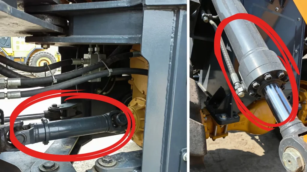
Clamping applications can also utilize a single-acting design. For example, a clamping fixture that uses hydraulic pressure to drive the clamping elements and relies on internal springs for release can reduce the number of hydraulic lines on the fixture. However, the springs must overcome seal friction, resistance from connecting components, and back pressure from the return line. If multiple fixtures are released simultaneously, the resistance generated by shared return lines must also be verified; it is not sufficient to check only whether a single cylinder can retract.
Whether a single-acting cylinder is suitable for pressing or assembly applications depends on the return requirements. For mechanisms that only require downward pressure and where the tool can reliably return to its home position, a single-acting cylinder can meet the requirements; however, if the ram must retract the tool and overcome the clamping force on the workpiece during the return stroke, or if it must quickly return to its starting position, the design must be reevaluated. You can start by calculating the forces required for the working stroke and the return stroke separately: if the return stroke also requires active hydraulic pulling force, a standard hydraulic single-acting cylinder with an extension stroke is not suitable.
Benefits of a Simpler One-Port Circuit
Single-acting cylinders typically require only a single working oil line, with both oil inlet and return handled through the same port. Compared to double-acting designs that require two working oil lines, this often reduces the number of hoses, fittings, and the space needed for piping. For fixtures with limited installation space or lifting devices with simple operations, this makes assembly and routine inspections more convenient.
For example, a device that only requires hydraulic lifting and spring-assisted retraction can use a pump with appropriate return control and a single hydraulic line. You do not need to route a separate hydraulic retraction line, but you still need to incorporate pressure limiting, return flow, and necessary load-holding functions. A single port simply means a simpler connection; it does not imply that the entire system requires only a cylinder and a pump.
When comparing costs, you should factor in the cylinder, valves, hoses, return mechanisms, and control requirements together. A single-acting solution may reduce piping complexity, but if a large spring mechanism or external drive is required for reliable reset, the overall advantage may be diminished. Also, do not assume that having “one less hose” necessarily means it is more energy-efficient or durable; these performance characteristics still depend on the complete circuit and actual operating conditions.
Limits in Controlled Retraction and Bidirectional Force
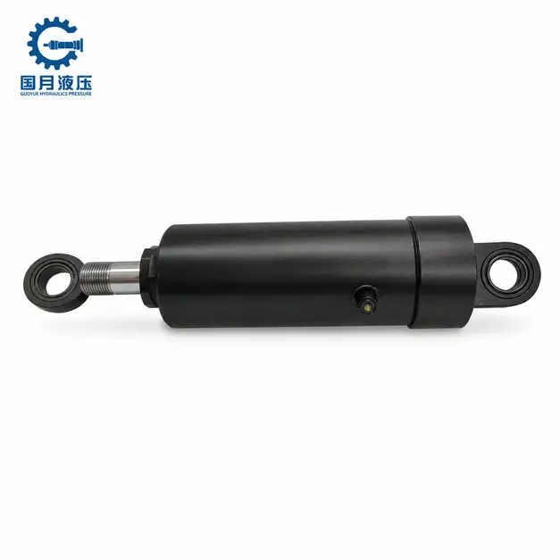
Single-acting cylinders can achieve controlled retraction, but the retraction force still comes from a spring or an external load. By adjusting the return flow rate, the descent or retraction speed can be limited. For example, a gravity-fed lifting mechanism can use an appropriate valve to control the return flow and prevent rapid descent. Parker’s documentation on single-acting telescopic cylinders also explains that retraction speed can be limited by throttling the return port or using a properly sized orifice.
The limitation is that when the return force is insufficient, opening a valve or reducing the throttle cannot generate retraction force out of thin air. Spring force, load weight, mechanical angle, and changes in oil temperature may also affect the return speed. Therefore, if you need to maintain a specified retraction time under both unloaded and loaded conditions, you should verify performance under the most adverse conditions; you cannot rely solely on a single successful operation to make a judgment.
If the equipment requires both thrust and active pulling force in the opposite direction, a double-acting cylinder is typically more suitable. For example, a horizontal material-feeding mechanism that pushes material during extension but must also pull the slide back or overcome clamping resistance during retraction requires reliable bidirectional force. While a double-acting design can provide hydraulic retraction force, maintaining a stable speed and accurate positioning still requires appropriate valves, sensors, and control circuits—it cannot be achieved simply by replacing the cylinder.
Before finalizing a single-acting solution, you should verify three conditions: whether the return force is reliable throughout the entire stroke, whether the return time meets requirements under the most adverse operating conditions, and whether load holding and descent control have been properly addressed. If any of these conditions cannot be met, you should adjust the return mechanism or consider a double-acting solution. For equipment requiring personnel to enter the area beneath a raised load, reliable mechanical support must also be provided; position holding cannot rely solely on the cylinder and valves.
Single Acting vs. Double Acting: What Changes in the Circuit?
A single-acting circuit provides hydraulic power to the cylinder in only one direction, with the return stroke relying on a spring or external load; a double-acting circuit alternately supplies oil to both sides of the piston, providing hydraulic power in both the extension and retraction directions. Therefore, the difference is not merely an additional oil line, but also involves the connection method of the directional control valve, the return oil path, as well as load control and shutdown procedures.
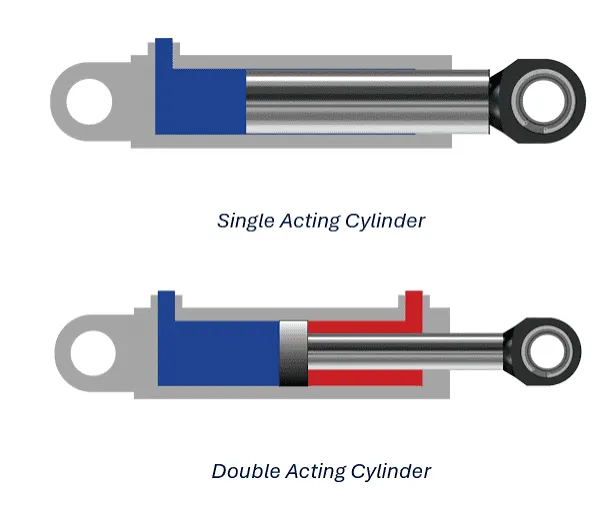
One Powered Stroke vs. Two Powered Strokes
In a common single-acting hydraulic cylinder designed for extension, pressure oil enters the cylinder through one working port, pushing the piston rod outward. During retraction, the same port acts as a return port, and a spring, gravity, or an external mechanism pushes the piston rod back to its original position. Opening the return path merely allows retraction; it does not mean the circuit can actively pull the piston rod back. For example, a dump truck’s lifting circuit can use hydraulic power to raise the bed, then rely on the bed’s weight to complete the descent.
Double-acting cylinders typically have two working ports. During extension, pressurized fluid enters the rodless chamber—the side of the piston without a piston rod—while fluid from the rod chamber is returned to the tank; during retraction, the two fluid paths switch roles. You must ensure that one side can receive oil while the other can discharge it. If the return side is blocked, the cylinder will be unable to move normally and may even generate abnormal pressure.
For example, if a horizontal material-pushing mechanism only needs to push forward and has a reliable spring mechanism for the return stroke, a single-acting configuration can be considered. If the return stroke also requires pulling the slide back or removing a jammed tool, a double-acting configuration is more suitable. However, bidirectional hydraulic drive does not imply that the force and speed are the same in both directions: in a standard single-rod double-acting cylinder, the effective area of the rod side is smaller, resulting in a theoretically lower retracting force at the same pressure and a faster retracting speed at the same inflow rate. When selecting a cylinder, the requirements for both extension and retraction should be verified separately.
Three-Way vs. Four-Way Valve Requirements
Single-acting cylinders are typically equipped with three-way directional control valves. “Three-way” refers to three main ports: the pressure port (P), the tank port (T), and the cylinder working port (A). During extension, ports P and A are connected; during retraction, ports A and T are connected. If an independent holding position is required, a three-way, three-position valve with the appropriate hydraulic circuit functionality can be selected; “three-position” indicates that the spool has three operating positions. Some simple systems may also use a manual pump with a return valve; however, a three-way, three-position valve should not be considered the sole configuration for all single-acting circuits.
Double-acting cylinders are typically equipped with four-way directional control valves, which have four main ports: P, T, A, and B. Taking the example where port A connects to the rodless chamber and port B connects to the rod chamber, during extension, the connections are P→A and B→T; during retraction, the connections are P→B and A→T. A four-way two-position valve can switch between two movement directions, while a four-way three-position valve adds a neutral position; however, the function of the neutral position still depends on the spool’s flow path.
When selecting a valve, you should examine the hydraulic symbols and verify the flow connections for the extension, retraction, and stop positions one by one. For example, one type of neutral position may connect P to T while sealing the cylinder’s working ports, allowing the pump flow to return to the tank; another type may allow the cylinder’s working ports to connect to the tank as well, in which case the load could drive the cylinder’s movement. You cannot assume that the cylinder will remain stationary simply because it is a “three-position valve.” Even if the working ports are sealed, leakage from a standard spool valve may cause positional drift, requiring specialized measures to meet load-holding requirements.
Control, Energy Use, and Failure Considerations
In terms of control, a single-acting circuit can limit retraction speed by adjusting the return flow rate, but actual movement is still affected by return forces. For example, the descent behavior of an empty car may differ from that of a fully loaded car. Double-acting circuits can actively provide retraction force and are better suited for mechanisms requiring reliable no-load return or bidirectional work; however, precise positioning and stable speed still depend on the valve, load, and control system. When gravity may cause the load to move, both types of circuits require appropriate descent control; controllability cannot be determined solely by the type of cylinder.
Energy consumption should also not be judged solely based on whether the system is single-acting or double-acting. Single-acting cylinders typically do not require the pump to provide retraction power during retraction; however, if the pump continues to supply oil at high pressure, energy is still consumed. For example, if a fixed-displacement pump continues to supply oil after the cylinder has stopped, and the flow can only return through a relief valve under high pressure, this will result in energy loss and heat generation. Therefore, you should verify whether the pump can be unloaded during the stop and return phases—that is, whether the supply pressure can be reduced or the pump can be shut off as designed. Although double-acting circuits involve a hydraulic retraction process, the overall energy consumption of the machine must still be compared based on pressure, flow rate, and operating time.
The focus of troubleshooting also differs. If a single-acting cylinder extends normally but fails to retract, you should focus on checking the return force, spring condition, return valve, and connection restrictions; If a double-acting cylinder fails to move in one direction, you must also check the corresponding supply path, the return path on the opposite side, and whether the directional control valve is switching correctly. Both types of cylinders can be affected by leaks, contamination, or mechanical binding; you cannot conclude that the cylinder is damaged simply because it “fails to move.”
Before modifying the circuit, a practical check is to determine how the load will move in three distinct states: during normal operation, when oil supply is stopped, and when power is lost or a hose fails. Single-acting cylinders do not necessarily retract automatically after power is cut off, nor do double-acting cylinders reliably hold their position after the pump stops. Equipment requiring load holding should be equipped with load-holding valves or mechanical locks according to actual risks; reliable mechanical support must be in place before personnel enter the area beneath a raised load.
What Should Engineers Specify Before Selecting One?
Before selecting a single-acting hydraulic cylinder, you need to determine the force required for the working stroke, the distance to be traveled, and what will drive the return stroke. Then, determine the structure and seal configuration based on the actual pressure, operating frequency, speed, and hydraulic fluid. Providing only the cylinder bore and stroke is often insufficient to determine whether the cylinder will operate reliably in the equipment.
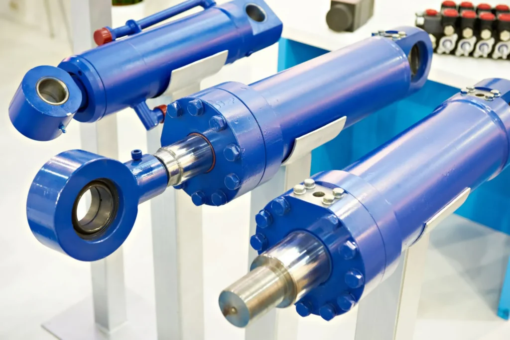
Required Force, Stroke, and Mounting Orientation
First, you should specify the axial thrust required by the cylinder, rather than just the weight of the equipment or load. Axial thrust is the force acting along the direction of the piston rod. If the cylinder lifts a car body via a connecting rod, the required thrust will vary with the angle of the mechanism; if it drives a horizontal slide, you must also consider friction, starting resistance, and acceleration requirements. Therefore, it is best to provide a schematic diagram of the mechanism, the load position, and the maximum load conditions throughout the entire stroke.
Stroke refers to the distance the piston rod travels from the retracted position to the extended position. You should also specify the required working stroke, the installed length when fully retracted, and the available space at maximum extension. For example, just because a mechanism needs to move 200 mm does not necessarily mean a cylinder with a 200 mm stroke is suitable; you must also verify connection points, assembly tolerances, and end stops. Do not assume that the cylinder’s internal end stops can withstand repeated impacts from the equipment.
The installation orientation must also be specified, including horizontal, vertical, or inclined mounting, as well as connection methods such as hinged or flanged. Provide load and installation diagrams showing the cylinder in its fully extended state so that the supplier can verify the piston rod’s buckling resistance and lateral load capacity. Buckling resistance refers to the piston rod’s ability to resist bending instability when under compression. This verification is particularly critical for long-stroke thrust mechanisms; the rod diameter should not be determined solely based on theoretical thrust adequacy.
Return Method and Available Return Force
You must specify whether the hydraulic cylinder uses spring-assisted return, gravity-assisted return, or is retracted by an external mechanism, and indicate the minimum return force available throughout the entire stroke. “Gravity-assisted return” only describes the source of the force; it does not prove that this force is sufficient. The return force must overcome seal friction, mechanical resistance, and the back pressure from the returning hydraulic fluid.
For example, the lifting mechanism of a dump truck should be verified under conditions where the empty body is lowered, particularly regarding the mechanism’s angle as it approaches the lowered position. For horizontally mounted clamps using spring-return mechanisms, the weight of the connected components, the resistance, and the allowable release time should be provided so that the supplier can determine the appropriate spring configuration. Springs must be selected based on actual load and friction conditions; simply stating “with a return spring” is insufficient.
Working Pressure, Duty Cycle, and Speed
Pressure parameters should distinguish between normal working pressure, maximum possible pressure, and the relief valve set point. A relief valve limits circuit pressure, but its set point does not replace verification of actual pressure peaks. You should provide pressure conditions at the cylinder location; if only pump outlet data is available, specify the measurement location, as pressure losses in valves and piping can affect the actual available thrust.
A work cycle is the process by which the equipment repeatedly completes the sequence of “extend, hold, retract, and wait.” You should specify the number of cycles per minute, the duration of each phase, the daily operating time, and whether continuous full-load operation occurs. For example, “6 cycles per minute” is not sufficiently detailed; continuous operation for 8 hours differs from short daily operations in terms of requirements for temperature rise, seal wear, and return stroke stability.
Regarding speed, it is best to specify both the target extension speed and the allowable retraction time separately. For example, you might specify “extend a 200 mm working stroke within 4 seconds, with retraction taking no more than 8 seconds,” rather than simply stating “fast operation.” The extension flow rate can be preliminarily calculated using Q = A × v; the retraction time must be verified based on the force provided by the spring or load, as well as the actual return oil resistance. The pump’s rated flow rate cannot be directly equated to the actual flow rate entering the cylinder.
Seal and Fluid Compatibility
You should provide the brand, complete model number, and technical data sheet of the hydraulic fluid, along with the minimum startup temperature, normal oil temperature, and maximum anticipated oil temperature. Simply writing “hydraulic oil” is insufficient, as mineral oil, water-glycol, and phosphate ester fluids may have different requirements for seal materials. Viscosity grades primarily describe the fluid’s viscosity characteristics and do not, by themselves, guarantee chemical compatibility.
For example, nitrile rubber (NBR) is commonly used in mineral oil hydraulic systems, but the specific formulation must still be matched to the temperature and fluid. Ethylene propylene diene monomer (EPDM) rubber can be used with certain phosphate ester fluids but is generally not suitable for mineral oil. Do not treat any single material as a universal choice for all fluids, nor should you directly apply the temperature range from another cylinder model. Ultimately, confirmation should be based on the specific seal formulation and the fluid supplier’s data.
When verifying compatibility, check the entire sealing assembly, not just the piston rod seals. Piston seals, static seals, support rings, and other components in contact with the medium must all be inspected. You should also account for external environmental factors such as dust, silt, and cleaning agents. For single-acting cylinders with low return force, seal selection must also consider friction: chemical compatibility only confirms that the material is suitable for contact with the medium; it does not guarantee that the cylinder will retract smoothly.
Frequently Asked Questions About Single Acting Hydraulic Cylinders
Can a Single Acting Cylinder Pull a Load?
Yes, but a structure or connection method suitable for pulling applications must be used. “Single-acting” means that hydraulic force acts in only one direction of motion; it does not necessarily mean that this direction is extension. Specialized single-acting pull cylinders can pull a load by hydraulically driving the piston to extend, then returning to the retracted position via a spring or other means. Some hollow-piston cylinders can also be used for pulling or tensioning when paired with a tie rod passing through the center bore and specialized attachments.
For example, when pulling two components together, you can select a pull cylinder with a rated pull force that meets the requirements. However, you cannot rely on the return spring of a standard hydraulic extension-type cylinder as a power source capable of pulling back a heavy load. **When selecting a cylinder, you should confirm the hydraulic drive direction, rated pull force, load-bearing capacity of the mounting hardware, and the return mechanism. ** If the equipment requires pushing during extension and pulling during retraction—meaning active hydraulic power is needed in both directions—a double-acting configuration should generally be considered.
Does a Single-Acting Cylinder Need a Return Line?
A return path is required, but it is generally not necessary to connect a separate return line from the cylinder. Single-acting cylinders typically use the same working port and the same hose for both oil inlet and return. During retraction, the fluid returns along this hose to the control valve and then flows into the reservoir. When using a manual pump with an integrated reservoir, the return path may be located inside the pump body; when using a separate valve manifold, the valve’s reservoir port typically needs to be connected to the reservoir.
For example, in a lifting cylinder connected to a manual pump via a single hose, once the return valve on the pump is opened, the fluid returns along the same hose. You should check whether the entire return path is unobstructed, rather than simply counting the number of hoses. Improperly connected quick-connect fittings, closed valves, or obstructed lines can all prevent the cylinder from retracting. Stopping the pump is not a substitute for opening the return path.
Can a Single-Acting Cylinder Stop Mid-Stroke?
Yes, but the circuit must be designed with mid-stroke stop and hold capabilities. The cylinder can stop midway through its stroke when a control valve seals the cylinder’s working port, trapping the hydraulic fluid within the working chamber. However, simply stopping the oil supply does not guarantee that the position will be held; the actual result depends on the valve’s communication status, leakage, and load conditions.
For example, a lifting mechanism can stop at a specified height, but “stopping movement” and “long-term, reliable holding” are two distinct requirements. Valve or seal leakage may cause slow drift; hydraulic fluid is somewhat compressible, and load variations may also cause displacement. You should specify the holding time, load, and allowable positional drift to the supplier before determining whether a load-holding valve, position feedback, or mechanical locking is required. Before personnel enter the area beneath a lifted load, reliable mechanical support must be established; do not rely solely on a closed hydraulic circuit.
Why Does Retraction Take Longer Than Extension?
Because extension is driven by oil supplied by a hydraulic pump, while retraction relies on a spring or external load; the retraction force may be smaller, and it must also overcome backflow resistance. However, retraction is not necessarily slower than extension. When the load is heavy and the return oil passages are unobstructed, retraction can also be very fast, so the descent speed must be properly controlled. Hose length and piping restrictions can both affect the actual retraction time.
For example, a spring-return cylinder may slow down as it nears full retraction because the available spring force decreases as a compressed spring gradually releases. Gravity-return mechanisms may slow down as the angle of the connecting rod changes. During cold starts, higher oil viscosity may also increase return flow resistance. Therefore, you cannot directly calculate the retraction time based on the pump’s oil delivery flow rate.
If retraction slows down noticeably, you should check the retraction force, valve positions, quick-connect fittings, and return lines after securely supporting the load, and compare the cycle time under the same load and oil temperature conditions. If the cylinder only stops during the final stage of retraction, focus on verifying the retraction force and mechanical resistance during that final stage; if the entire retraction process is slow, check the return flow restriction as well.
Choosing a Trusted Hydraulic Cylinder Manufacturer
From standard hydraulic cylinders to custom solutions, we help you improve equipment performance, delivery reliability, and batch consistency
Explore Rivmate Cases

Hey There, I'm Melody!
We are a hydraulic cylinder manufacturer. For over 20 years, we have focused on producing reliable hydraulic cylinders. Need a hydraulic cylinder solution? Feel free to contact us.