Home / What Causes Hydraulic Cylinder Drift
What Causes Hydraulic Cylinder Drift
- Author: GY Hydraulic
- 20+ Years of Manufacturing
Hydraulic cylinder drift may be caused by internal leakage within the cylinder, leakage from control valves or valves responsible for maintaining the load position, external leakage, and temperature fluctuations. Changes in load, pressurisation of the hydraulic fluid and air, mechanical clearances and structural deformation may also cause positional changes that appear to be drift. You must first identify exactly which component is moving before investigating the cause of the fluid flow or volume change.
Drift alone does not prove that the piston seals are damaged. Conversely, a temporary lack of movement in the hydraulic cylinder does not prove that there are no internal leaks. This GY Hydraulic guide will help you distinguish between these situations, measure drift under comparable conditions, and determine whether the hydraulic cylinder, valves or mechanical components require inspection.
Table of Contents
What Hydraulic Cylinder Drift Means
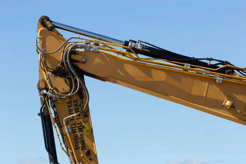
Hydraulic cylinder drift refers to the phenomenon where the piston rod undergoes unexpected displacement when the system is required to maintain a specific position. The piston rod is the metal rod that extends from the cylinder body and connects to the load. Drift can manifest as retraction, extension, or the slow vertical movement of the mechanism; it does not solely refer to a heavy object falling. Before making a judgement, you should also confirm that the control system has not actively issued a position correction or descent command.
For example, if a working arm slowly descends after coming to a halt, you must first distinguish whether the piston rod has retracted relative to the cylinder body, or whether the position of the working arm has changed due to play in the pins, movement of the mounting bracket or deformation of the frame. If you focus solely on the end of the working arm, it is easy to mistake mechanical movement for an internal problem with the hydraulic cylinder.
You should begin by recording, from outside the protected area, the rod position, the position of the mechanism, the direction of movement, and the status of the pump (whether running or stopped). At the same time, check for any visible external leaks, but do not use your hands to locate points of leakage under pressure. Whether a certain degree of drift is permissible must be determined based on the technical requirements of the equipment and a risk assessment; the claim that ‘all hydraulic equipment drifts slowly’ must not be used as a justification for continuing operations.
Piston-Seal Bypass and Internal Cylinder Leakage
Piston-seal bypass can contribute to drift, but whether the drift persists also depends on the direction of the load and other hydraulic pathways. This determines whether you can interpret the hold-position test correctly, so it is worth clarifying this first.
1. Understand What Piston-Seal Bypass Changes
The piston is the component within the cylinder that converts hydraulic pressure into thrust; the piston seal is responsible for preventing fluid from flowing from one side of the piston to the other. Seal wear, assembly damage or scratches on the cylinder bore may allow fluid to bypass the piston; this is known as a bypass. Certain designs also feature an internal static seal at the connection between the piston and the rod—that is, a seal where the mating surfaces do not slide relative to one another—which must also be inspected.
Bypass weakens the ability to maintain a pressure differential between the two chambers, which may affect thrust, position holding and heat generation. However, the fact that ‘fluid has reached the other chamber’ does not necessarily mean it has left the hydraulic cylinder. You must therefore also analyse how the total fluid volume changes, and whether the fluid can enter or exit via valves or external leakage paths.
2. Why Internal Leakage Does Not Always Produce Continuous Drift
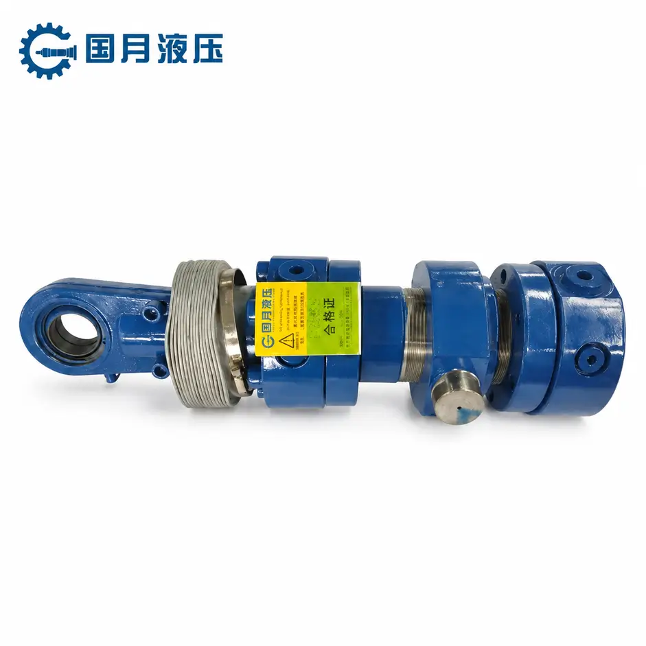
Take a common single-rod, double-acting cylinder as an example: it has a piston rod extending from only one end, and both extension and retraction are driven by hydraulic fluid. The rodless chamber is the side of the piston without the rod, whilst the rod chamber has a smaller effective area due to the space occupied by the rod. As the areas of the two chambers differ, the volume of fluid required for the same displacement also varies.
When the load pushes the rod into the cylinder, the rod’s entry reduces the total space available to accommodate oil.
If both oil ports are truly sealed with no external leakage, and temperature changes are disregarded, the internal bypass cannot allow the excess oil to be continuously discharged. The system may reach equilibrium after a limited displacement and pressure redistribution; therefore, even with a sealed bypass, continuous retraction may not be detected.
This does not imply that leakage is harmless. When the pressures in the two chambers are close, the net thrust may not necessarily be zero due to the difference in the pressurised areas on either side; the chamber pressure required to support the same load may increase. If the pressure causes the load to keep the valve open, allowing the fluid to find a path out of the cylinder, drift may continue. The absence of movement should not be taken as proof of pressure safety.
3. Recognise Where This Explanation Does Not Apply
The above analysis applies specifically to single-rod cylinders where the load pushes the rod in. The situation will differ when the load pulls the rod out, in double-rod cylinders with equal areas, when gas or cavitation is present in the chamber, or when there is actual leakage in the valve assembly. Do not treat this principle as a rule of thumb that ‘blocking both ports will prevent all hydraulic cylinders from moving’.
When troubleshooting in practice, you should provide the cylinder bore diameter, rod diameter, load direction and circuit diagram, so that maintenance personnel can select an appropriate bypass verification method.
Control-Valve, Check-Valve, and Load-Holding Valve Leakage
Control valves are responsible for switching or regulating the flow of hydraulic fluid. Common spool valves rely on the spool—the moving control component within the valve—to alter the connection configuration; as there is a clearance between the spool and the valve body, ‘returning the handle to the neutral position’ does not necessarily mean that all ports are completely sealed. In some valves, the neutral position is designed to connect the working ports to the reservoir; it is therefore essential to consult the schematic diagram first.
Check valves allow fluid to flow in a specified direction and prevent reverse flow; hydraulically controlled check valves can also be opened by pilot pressure, which is the hydraulic signal that activates the control valve. Particles trapped in the valve seat, damage to the sealing surfaces, or the presence of unintended pilot pressure may all affect the valve’s holding performance. You should verify the specific leakage path; not all leakage between valve ports should be assumed to be leakage from the load chamber to the reservoir.
A balancing valve is a type of valve used to maintain the load and regulate load return flow during movement. Its opening characteristics differ from those of a pilot-operated check valve; the two cannot be interchanged simply because they have the same port configuration. For example, if drift occurs only when operating a different hydraulic cylinder, one should check whether shared pressure is entering the originally stationary circuit through gaps in the control valve, rather than immediately dismantling the cylinder.
Thermal Expansion, Cooling, and Trapped Pressure
Hydraulic fluid expands when heated and contracts when cooled. If a volume of fluid is confined within a hydraulic cylinder or pipework by a valve, temperature changes may result in changes in pressure or position. The term ‘trapped pressure’ here refers to the situation where the fluid remains confined and maintains its pressure; this condition may persist even after the pump has been switched off. One must not assume that all chambers have been depressurised simply because the main pressure gauge reads zero.
For example, when equipment is left stationary after being warmed up and gradually cools down, the load may cause a positional change as the fluid contracts; conversely, when exposed to sunlight and the temperature rises, the pressure within the sealed chamber may increase. Whether movement occurs, and in which direction, depends on the temperatures of the two chambers, the constraints, the load and the valve connections. HAWE’s technical documentation also states that circuits that remain sealed and maintain pressure for extended periods are affected by temperature rises and falls.
You should record changes in oil temperature and displacement on the same chart, rather than merely comparing positions before and after shutdown. For sealed oil circuits susceptible to heat, the protective pathways against thermal expansion pressure must be verified during the design phase; do not block existing pressure relief passages in an attempt to eliminate drift. If drift persists after the system has stabilised at a constant temperature, leaks must still be investigated; movement caused by temperature changes does not in itself constitute evidence of intact seals.
External Loads, Geometry, and Mechanical Movement
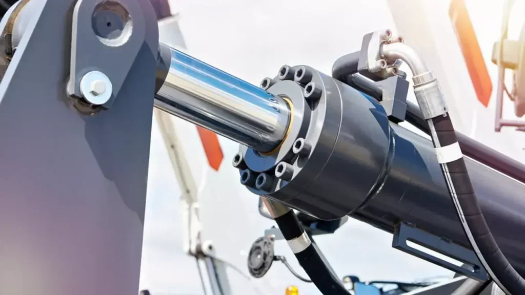
The same weight does not necessarily exert the same force on a hydraulic cylinder. Changes in the angle of the mechanism alter the lever arm—that is, the effective distance from the force to the centre of rotation—and therefore, when the working arm changes its orientation, the thrust exerted on the hydraulic cylinder and the pressure within the chamber may differ significantly. One cannot directly compare the drift speeds at two different lever arm angles as an indication of seal integrity.
Mechanical clearance and elastic deformation must also be examined separately. For example, after a movement has ceased, the pin may re-engage within the clearance, or the load-bearing frame may undergo limited deformation, causing the end position to change, whilst the piston rod may remain virtually stationary relative to the cylinder body. Hydraulic fluid compression and hose expansion may similarly cause initial settlement; this is not the same type of evidence as movement caused by long-term, continuous fluid leakage.
You should, as far as possible, observe both the position of the rod relative to the cylinder and the load position simultaneously, and record the mechanism’s orientation. If you detect movement of the mounting bracket, cracks in the connections or a sudden loss of load support, you must shut down the machine immediately in accordance with procedures; at this point, it is not appropriate to continue measurements to distinguish between ‘hydraulic or mechanical’ causes.
Contamination, Fluid Condition, and Temperature Effects
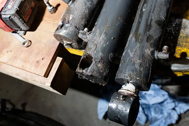
Contamination may simultaneously damage the seals, cylinder barrel and valve seats, and may also prevent the valve spool from returning to its intended position. Therefore, should drift occur suddenly, you should first check whether any pipework has recently been dismantled, whether the oil has been changed, or whether any abnormal particles have been found in the filter element or the oil. The fact that the oil appears clean does not prove that it meets particle cleanliness standards; where contamination is suspected, samples should be taken and tested in accordance with specifications.
Viscosity refers to the thickness or thinness of hydraulic fluid as it flows, and typically decreases as the temperature rises. Under identical clearance and pressure differentials, lower viscosity may increase leakage; this is why drift is often more pronounced in some equipment after it has warmed up. However, temperature also affects seal condition, clearance fits and thermal expansion; one must not directly conclude that a valve is faulty simply because ‘drift is faster when the system is hot’.
If you have recently changed the oil, you should verify the oil type, viscosity grade and seal compatibility. Do not attempt to mask drift by adding thicker oil, as this may otherwise affect cold-start oil supply and valve control. Following inspection and repair, retest at the specified temperature; do not use cold oil test results to confirm that a fault occurring when the system is warm has been resolved.
How to Measure Drift Rate Safely
The basic calculation of the drift rate is straightforward: displacement divided by time. The challenge lies in ensuring consistency between safety protocols, the object being measured and the test conditions. If there is no safety test procedure applicable to the equipment, first record any external phenomena, then refer the matter to maintenance personnel to establish the test configuration; do not suspend heavy loads yourself to conduct position-holding tests.
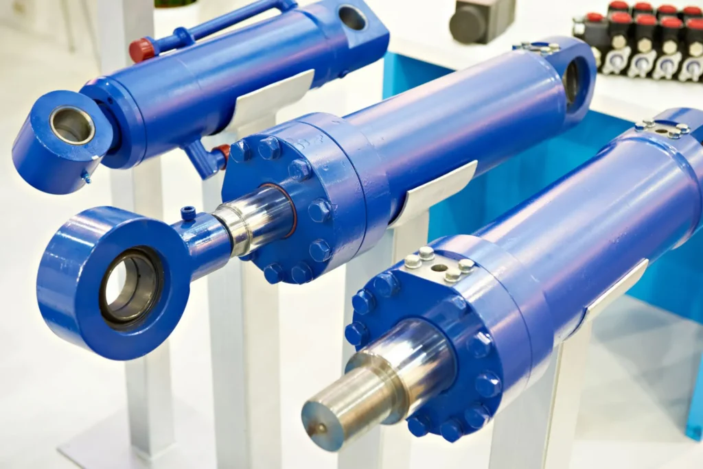
① Prepare a Controlled Test Condition
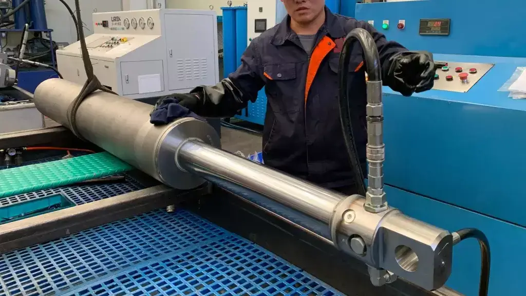
First, determine the load, orientation, piston position, oil temperature, control valve status and whether the pump is running, in accordance with the requirements for the complete unit. Measurements should be carried out from outside the danger zone. When observation under load is required, use the load-bearing, limit and protective configurations specified by the manufacturer; do not place wooden blocks there temporarily or allow personnel to stand beneath the load to take readings.
It is also essential to distinguish the role of the supports: before disconnecting hoses or installing instruments, the load must be reliably supported and the system depressurised; formal load-holding tests require the specified load to be applied to the system under test in accordance with the procedure. If the supports have completely taken over the load, the fact that the ‘hydraulic cylinder does not move’ does not prove that it has adequate load-holding capability. Do not remove the supports yourself to carry out additional tests; maintenance personnel must arrange for appropriate safeguards.
② Measure the Rod Relative to the Cylinder Body
Prioritise the use of displacement transducers suitable for on-site conditions, or fixed scales that can be read from outside the safety zone, to record the position of the piston rod relative to the cylinder body. Do not mark the chrome-plated rod surface, nor insert hand-held measuring instruments into mechanisms that may be in motion. The resolution of the measuring instrument should be sufficient to identify the displacement you need to assess; if no change is readable, this merely indicates that the change is below the instrument’s measurement capability for that particular measurement.
You may use the table below to maintain a record, thereby avoiding inconsistencies in conditions during subsequent retests:
| Item | Recommended Record Content | Why it is required |
|---|---|---|
| Load and configuration | Load status, working arm angle, hydraulic cylinder position | To determine the force distribution and possible mechanical amplification |
| Temperature | Oil temperature reading, measurement location and changes during the test | To distinguish between temperature effects and changes due to leakage |
| Control status | Pump running or stopped, valve position, whether other circuits are active | To confirm consistent hydraulic circuit conditions |
| Displacement and time | Initial rod position, final rod position, direction, start and end times | To calculate rates and distinguish between extension and retraction |
| Pressure and anomalies | Pressure at existing measurement points, external leaks, alarms, sudden movements | To assist in interpreting results and determining whether to halt the test |
③ Calculating the Rate Without Establishing a Pass Limit
The average drift rate can be expressed as: Drift rate (mm/min) = Piston rod displacement (mm) ÷ Observation time (min). For example, assuming that, under permissible test conditions, the piston rod retracts by 2 mm over a period of 10 minutes, the average retraction rate is 0.2 mm/min. This is merely a calculation example; it is not an actual measurement result from GY Hydraulic, nor is it a pass/fail limit.
To determine whether the result is acceptable, it must be compared against the requirements for that model under the specified load, temperature and observation time. A 2 mm drop at the end of the working arm cannot be directly equated with a 2 mm rod displacement; similarly, the drift rate cannot be directly converted into piston seal leakage until the leakage path has been identified.
④ Distinguish Between Initial Settling and Continuing Movement
If the procedure permits, displacement may be recorded in intervals to determine whether the movement is limited settling occurring immediately after the action has ceased, or continuing movement. In the former case, it is worth checking for air entrainment in the hydraulic fluid, mechanical clearances and structural deformation; in the latter, it is more necessary to trace the fluid pathways, although temperature changes may still affect the entire process.
Do not continue testing simply to complete the observation period after observing accelerated load drop, sudden jerks or abnormal pressure. Nor should full-stroke compliance be judged solely on the basis of a single brief position hold; if a fault occurs at a specific position, that position should be retained in the approved procedure as a condition for re-inspection.
How to Isolate the Cylinder from the Valve Circuit
The purpose of isolation is to determine in which section of the system the fault lies; it cannot be reduced to simply removing a pipe under load and then plugging the oil port. Altering the oil circuit changes the volumetric constraints and pressure conditions of the hydraulic fluid; therefore, the results before and after isolation must be interpreted in conjunction with the test boundaries.
1. Define What Remains Inside the Test Boundary
First, the maintenance technician should mark on the schematic diagram the two working fluid circuits, the pilot circuit, the pressure measurement points, and the retained pressure protection path. If the load-holding valve is mounted directly on the cylinder block, when isolating externally to the valve, you are typically still testing the ‘hydraulic cylinder and valve block assembly’. A valve block is a component that integrates valves and fluid passages; a fault in the assembly cannot be directly attributed to a piston seal leak.
For example, if the main valve has been ruled out but the hydraulically controlled check valve on the cylinder block remains within the measurement scope, it is still necessary to distinguish between seat leakage, pilot valve opening and internal cylinder bypass. Isolating only one hose without analysing the other oil circuit may also fail to achieve the intended result.
2. Use a Designed Test Arrangement
Before altering any connections, follow the procedure to support the load, isolate the power source and relieve pressure from the relevant chambers and accumulators. Accumulators are devices that store hydraulic energy and may continue to supply pressure even after the pump has been stopped. Test valve blocks, plugs, couplings, hoses and gauges must all be suitable for the pressures, fluid types and temperatures that may actually occur; the leakage from the isolation valve itself must also be taken into account.

Include Pressure Protection in the Test Plan
Conventional single-rod cylinders have different cross-sectional areas on either side, which can lead to pressure amplification under certain sealed conditions—that is, localised pressure higher than the supply pressure. Bosch Rexroth’s technical documentation explicitly states that this hazard may arise when one chamber is supplied with fluid whilst the other is sealed. Consequently, it is unreliable to select test fittings based solely on the pump’s relief setting, or to continue pressurising after sealing one chamber.
Maintenance personnel should use an approved test configuration to ensure that relevant pressures can be measured, overpressure protection is in place, and load movement is controlled. Do not rely on loosening fittings to check for oil leaks, nor discharge high-pressure oil directly into an open-top measuring cylinder; when quantitative measurement of bypass flow is required, use a suitable low-flow measuring device and a controlled discharge path.
3. Interpret Isolation Results as Evidence, Not a Verdict
Under comparable load, position and oil temperature conditions, isolation results can help you plan the next steps, but cannot independently prove that a component is either sound or faulty.
| Results observed after isolation | What conclusions can be supported | What cannot yet be proven |
|---|---|---|
| Drift significantly reduced or stopped | The original valve circuit or the excluded connection path may have contributed to the drift | The piston seal must be intact, as the sealing conditions themselves have also changed |
| Drift persists | Continue to inspect valves, hydraulic cylinders, external leaks and temperature effects within the test boundaries | The piston seal must be damaged |
| Pressure changes but rod position remains essentially unchanged | Analysis of temperature, compressibility and pressure redistribution within the chamber is required | The pressure drop is equivalent to a leak in a specific component |
| End-point bypass check passed, but mid-stroke conditions remain abnormal | Need to verify position-related damage and the coverage of the original test | The entire stroke has been verified as satisfactory |
If a piston seal bypass is still suspected, further verification should be carried out in accordance with the hydraulic cylinder manufacturer’s methods. Pressure testing during the mid-stroke requires specialised jigs capable of withstanding hydraulic thrust or a purpose-designed circuit; ordinary bench vices, clamping the piston rod or using makeshift shims to restrict movement must not be used.
Repair Options for Cylinder and Valve Leakage
Once internal leakage in a hydraulic cylinder has been confirmed, first inspect the mating components before deciding whether to replace only the seals. The piston seals, internal static seals, seal grooves, the inner wall of the cylinder barrel and the guide components should be inspected. Guide components are used to maintain the alignment of moving parts; if worn, they may cause new seals to become misaligned again. Seal kits must be matched in terms of model, groove dimensions, material, hydraulic fluid and operating conditions; they must not be purchased solely on the basis of visual similarity.
Once a leak in a valve assembly has been confirmed, the issue should be addressed according to the specific valve type. Particles lodged in the valve seat, damaged seals and wear on the spool mating surfaces each require different repair methods; cleaning may not necessarily restore a seal face that has already been damaged. When replacing valve assemblies, it is also essential to verify the neutral position connection method, leakage requirements, pilot conditions and pressure rating. Do not simply select replacement parts with identical connections and similar maximum flow rates, nor should you use an increased balancing valve setting to mask a bypass issue.
If external leaks or mechanical issues are present, the root causes must also be rectified. For example, in the case of oil leakage from a fitting, the type of seal and the fit should be inspected rather than simply tightening the fitting under pressure; where off-centre loading causes unilateral wear, installation and guidance issues should be corrected. Following repairs, retest under the original operating conditions where drift occurred, and check the motion control and protective functions; avoid commissioning the valve after testing it only under no-load conditions.

Preventing Drift with Correct Design and Maintenance
To prevent drift, first clearly specify the position-holding requirements: the direction and range of the load, permissible displacement, holding time, oil temperature, operating orientation, and the required behaviour in the event of a power failure or hose failure. One cannot simply provide the hydraulic cylinder supplier with the bore diameter and stroke and expect the same position-holding performance under all operating conditions.
Where low-leakage position holding is required, suitable seat-type holding elements should be evaluated; where movement driven by gravity or other external forces needs to be controlled, load control solutions such as balancing valves should also be assessed. Hydraulically controlled check valves primarily perform opening or closing functions and cannot automatically substitute for controlled, smooth lowering. The specific valve type, installation position, pilot conditions and thermal overpressure protection must be designed in conjunction; simply ‘adding a hydraulic lock’ should not be regarded as a solution to all instances of drift.
For maintenance purposes, you should maintain a drift log under fixed conditions and review the data following oil changes, seal replacements, valve replacements or installation adjustments. Ensure cleanliness during oil refilling and disassembly/reassembly, and inspect the hydraulic fluid, filter elements, external leaks and pin connections as required; specific inspection intervals should be determined according to the equipment and operating conditions. If personnel need to enter the area beneath the load or hazardous zones of the mechanism, prescribed mechanical locks or supports must be used; hydraulic position holding alone must not be relied upon.
When consulting GY Hydraulic regarding hydraulic cylinder configuration or replacement requirements, you may provide the nameplate, original drawings, cylinder bore and rod diameter, circuit diagrams, load direction, and drift records including oil temperature and measurement point specifications. This information helps to ensure that the selected model and repair solution are tailored to the actual operating conditions.
FAQs
Is some hydraulic cylinder drift normal?
Certain structures and circuits permit limited displacement under specified conditions, but this does not mean that all drift is normal. You need to consult the acceptance criteria for the machine or system in question; for movements that could cause injury or affect precision positioning, even if the displacement is minimal, they should be addressed in accordance with their risk and functional requirements.
Can a double-acting cylinder drift with good piston seals?
Yes. Valve leakage, external oil leakage, temperature changes or pressure from other circuits can all cause drift even when the piston seals are in good condition. You should inspect the entire hydraulic circuit, taking particular care to distinguish between fluid escaping from the load chamber and pressure oil accidentally entering a chamber.
Why does cylinder drift change as the oil warms up?
An increase in oil temperature typically reduces viscosity, which may increase clearance leakage and also affect seals, dimensional fits and the volume of sealed fluid. You should make comparisons under identical load, position and control conditions, and record the actual temperature; you must not directly attribute component wear to differences in operating conditions before and after warm-up.
Can a counterbalance valve stop hydraulic cylinder drift?
A suitable counterbalance valve can restrict reverse flow at the relevant ports and help control the load, but it cannot guarantee the elimination of drift caused by all possible factors. Internal cylinder bypasses, valve contamination, unintended pilot pressure and thermal overpressure activation must all be checked separately; the presence of a counterbalance valve alone does not guarantee that the system will not drift.
How quickly should a loaded cylinder be allowed to drift?
There is no universal mm/min value applicable to all hydraulic cylinders. Permissible values should be derived from the machine’s design, the manufacturer’s test requirements or applicable acceptance criteria, and must specify the load, temperature and observation period. If no limits are specified, you should first obtain the relevant technical requirements; the calculation examples in this article must not be taken as a standard of compliance.
Can trapped air cause apparent cylinder drift?
Yes. When the load changes, trapped air may be compressed, causing a change in position; this often manifests as initial settlement or a springy response. You should check recent disassembly, reassembly and bleeding records, and bleed the system in accordance with regulations; if movement persists, you must continue to investigate the fluid pathways and temperature factors.
Why does a hydraulic cylinder drift upward?
Upward drift may result from pressure oil entering the lifting chamber via valves, thermal expansion of the enclosed fluid, or other forces pulling the mechanism upwards. Even if the pressures in both chambers are similar, a net thrust may still be generated due to differences in effective area. You should clearly mark the corresponding extension or retraction direction for upward movement, and then make a judgement based on the pressures in both chambers and the circuit configuration.
When does cylinder drift require immediate shutdown?
Operations must be halted immediately in accordance with equipment procedures if drift could result in personnel being trapped, loads falling, or if it is accompanied by sudden acceleration, structural damage, oil spray or the failure of protective functions. Personnel must be evacuated from the danger zone, and inspections may only be carried out after the cylinder has been safely supported, the power source isolated and the pressure relieved; operation under load must not be continued merely to measure the drift speed.
Choosing a Trusted Hydraulic Cylinder Manufacturer
From standard hydraulic cylinders to custom solutions, we help you improve equipment performance, delivery reliability, and batch consistency
Explore Rivmate Cases

Hey There, I'm Melody!
We are a hydraulic cylinder manufacturer. For over 20 years, we have focused on producing reliable hydraulic cylinders. Need a hydraulic cylinder solution? Feel free to contact us.