Home / What Fail Safe Is Built Into The Hydraulic Lift Cylinders
What Fail Safe Is Built Into The Hydraulic Lift Cylinders
- Author: GY Hydraulic
- 20+ Years of Manufacturing
Common safety measures for hydraulic lifting cylinders include load-holding devices or burst protection valves at the cylinder port, as well as pressure-limiting, speed-limiting, mechanical interlocks, interlocking mechanisms and emergency stop functions integrated into the complete machine. However, not every cylinder is fitted with these devices, nor is there a single valve capable of addressing all types of failure. You need to verify how the complete machine maintains the load, restricts hazardous movement and allows for safe handling in the event of a specified failure.
This GY Hydraulic guide will help you distinguish between the different protective functions. Some devices are fitted directly to the cylinder port or integrated into a valve block, whilst others form part of the hydraulic power unit, mechanical structure or electrical control system. Therefore, when determining whether a lifting device is equipped with the required protection, you should consider the machine model, hydraulic schematic and applicable standards; you should not rely solely on the appearance of the hydraulic cylinder or product descriptions stating that it is ‘equipped with a safety valve’.
Table of Contents
The Short Answer: Lift Cylinders Use Layered Fail-Safe Protection
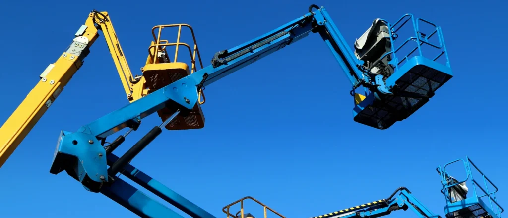
‘Fail-safe’ refers to a mechanism that, under specified fault conditions, causes the equipment to enter or maintain an intended safe state. For lifting equipment, the objective may be to hold the load, limit the descent speed, halt dangerous movements, or ensure a controlled descent along a designated path. The specific objective depends on the equipment’s intended use and should not be interpreted to mean that ‘the platform will remain absolutely stationary should any component fail’.
Multi-layered protection means implementing appropriate measures for different risks. For example, during normal shutdown, a load-holding device restricts the outflow of hydraulic fluid; in the event of a load hydraulic hose rupture, suitable cylinder port protection limits dangerous descent; and when maintenance personnel need to access the area beneath the platform, mechanical supports and energy isolation as specified by the manufacturer must be used. Energy isolation involves cutting off and controlling energy sources—such as electrical power, hydraulics and gravity—that could cause hazardous movement.
You may begin by consulting the equipment documentation to identify how position holding, abnormal descent prevention, pressure limitation, maintenance support and emergency procedures are respectively implemented. Multi-layered protection does not equate to the mandatory installation of multiple valves in series; a single, validated component may fulfil multiple functions, whilst certain equipment may require alternative configurations. The basis for judgement should be the protective functions and validation results, rather than the number of valves.
Load-Holding Check and Counterbalance Valves
The core function of a load-holding valve is to control the path through which the hydraulic fluid flows out of the hydraulic cylinder. In lifting mechanisms subject to gravity, the load may continue to push the piston and force fluid out even after the pump has stopped. Therefore, stopping the pump alone cannot replace a reliable load-holding design.
① Separate Load Holding from Motion Control
A standard check valve allows fluid to flow in one direction and blocks flow in the opposite direction. Hydraulically controlled check valves build on this principle by utilising pilot pressure to open the reverse passage; the pilot pressure is the hydraulic signal used to control the valve’s operation. They are generally suitable for position locking, but once opened, they should not be assumed to be capable of independently controlling the smooth descent of a gravity-loaded load.
Balance valves, on the other hand, are used for load holding and motion control, regulating oil discharge on the load side through load pressure, spring action and corresponding pilot control. ‘Load override’ refers to a situation where the load’s own weight or an external force drives the actuator, potentially causing it to move faster than the oil supply control allows. When selecting a balancing valve, such movements must be taken into account, rather than merely confirming whether there is any leakage whilst stationary.
| Required function | Tasks typically performed by a hydraulically controlled check valve | Tasks typically performed by a balancing valve |
|---|---|---|
| Maintaining position when stationary | Prevents reverse flow on the load side and restricts fluid outflow | Closes the load-side return path under design conditions |
| Upon receiving a lowering command | Pilot pressure causes the valve to open; the lowering speed still requires appropriate control | Regulates return flow in conjunction with pilot pressure to assist in controlling load movement |
| Load-driven mechanisms | Stability during lowering cannot be determined by the locking function alone | Commonly used to control load override, but correct selection and circuit matching are essential |
| Replacing valve components | Full functionality and control conditions must be verified | Even if the mounting holes are identical, valves cannot be directly interchanged |
For example, a lifting mechanism that can lock in position when stationary may still exhibit jerking or fluctuating speeds during descent. You should have engineering staff check the compatibility of the load, valve characteristics and speed control; simply replacing the hydraulically controlled check valve with a larger one is not sufficient. Sun’s technical documentation distinguishes between applications involving position locking and those involving load motion control.
② Check Where the Valve Is Installed
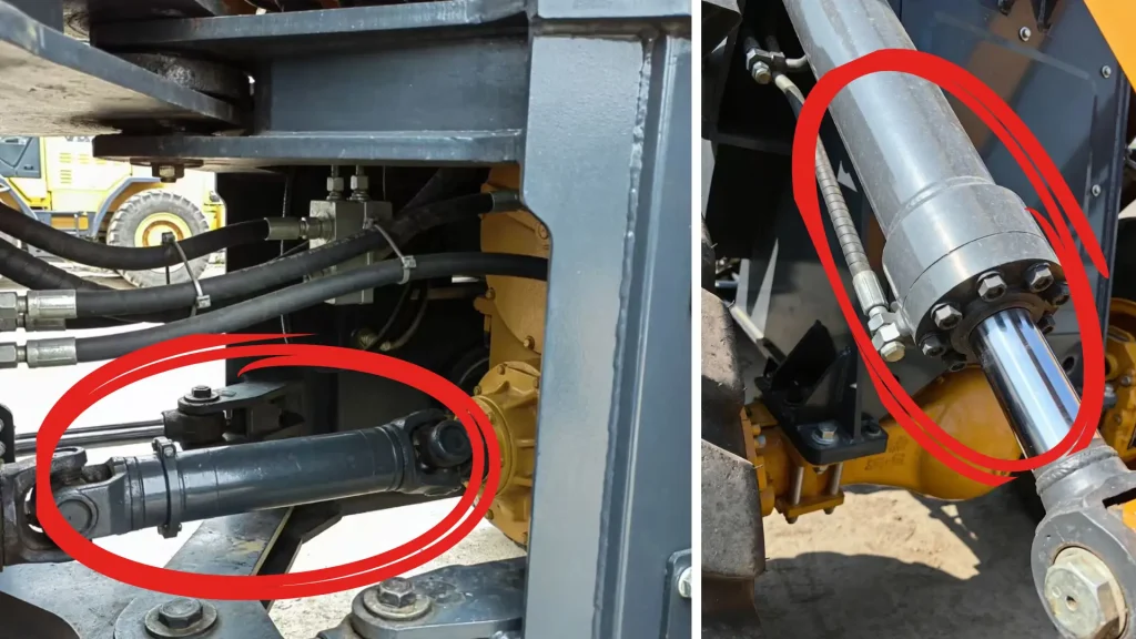
The installation location determines which rupture points are protected. Valves used for cylinder-side burst protection typically need to be installed directly or, in accordance with the approved design, immediately adjacent to the hydraulic cylinder’s load port, to avoid leaving an unprotected section of hose between the cylinder and the protective valve. If there is still a section of hose between the valve and the cylinder, a rupture in this section may mean that the fluid does not pass through the valve’s shut-off position at all.
You should verify the connection between the ‘cylinder—safety valve—hose’ both on the schematic diagram and in practice. For example, although there is a non-return valve in the power unit, should the load-carrying line from the power unit to the hydraulic cylinder rupture, it may not necessarily prevent fluid inside the cylinder from escaping through the rupture. Where the valve is installed is just as important as what it is called.
③ Match the Valve to the Actual Lift
Confirm Pressure and Pilot Conditions
When selecting a valve, you should provide the load pressure range throughout the entire lifting stroke, the cylinder bore and rod diameter, the pilot pressure conditions, and the return line back pressure. Back pressure is the pressure present on the return line and can affect the opening and control performance of some valves. The valve’s pilot ratio describes the relationship between the control pressure and the valve’s opening; this should be selected by engineering personnel, taking into account stability and pressure supply conditions.
Do not treat a specific pressure setting multiplier as a universal rule for all lifting cylinders, nor should you adjust the balancing valve yourself to resolve slow operation. The forces acting on a scissor lift mechanism vary at different heights; adjusting based solely on readings from a single position may compromise control performance at other positions.
Confirm Flow and Release Requirements
Verify the maximum normal descent flow rate, permissible leakage, fluid and temperature ranges, and confirm how emergency release is controlled. Flow rate is the volume of fluid passing through per unit of time. Valves must satisfy both normal motion requirements and specified response requirements in the event of a fault; if the equipment carries passengers, the relevant overall machine requirements must also be provided to the supplier for confirmation.
Velocity Fuses and Hose-Burst Valves
Speed safety valves typically activate in response to an abnormal increase in hydraulic fluid flow. The term ‘speed’ here primarily refers to the flow of hydraulic fluid, rather than the speed at which the platform descends, as measured directly by a sensor. Taking a common flow-activated burst valve as an example, when the flow rate from the load-bearing chamber reaches the set trigger condition, the valve closes the corresponding passageway to restrict hazardous movement. Whether the valve completely shuts off the flow or merely restricts it depends on the product design and cannot be determined solely by the product name.
This form of protection has clear limitations. Slow leaks may not reach the trigger flow rate, nor does internal cylinder seal bypass necessarily pass through the valve; furthermore, if a rupture occurs between the safety valve and the cylinder, the valve may still be unable to protect that specific location. For example, if an external hose remains intact but the platform descends slowly, one should not conclude that the safety valve has failed simply because it did not activate, nor should other faults be ruled out on this basis.
When selecting and configuring the valve, you should verify the maximum normal oil discharge flow rate, the preset trigger flow rate, the installation orientation, the permissible pressure, the oil temperature and the reset method. A trigger value that is too low may interfere with normal descent, whilst one that is too high may fail to meet the requirements for protection against abnormal descent. These parameters should be selected and verified in accordance with the requirements of the complete machine and should not be adjusted on-site by the user based on feel alone.
Pressure-Relief and Overload Protection
A relief valve is a device that diverts hydraulic fluid once a set pressure is reached, thereby limiting the pressure in the corresponding circuit. Its primary function is to prevent unauthorised pressure build-up in the pressure supply or associated hydraulic circuits; it must not be regarded as a lock designed to prevent the load from lowering. Whether the valve can protect a particular oil chamber also depends on whether that chamber is effectively connected to the valve; for fluid sealed off by other valves, thermal expansion or localised pressure build-up may need to be considered separately.
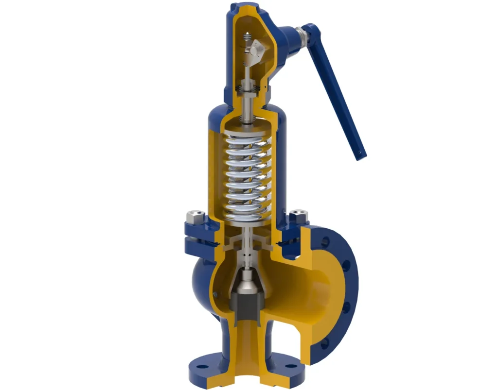
Overload protection, on the other hand, requires an assessment of whether the load or associated forces exceed the machine’s permissible limits; this may involve the use of signals such as pressure, load or torque, and the restriction of corresponding movements. A single main relief valve alone may not be sufficient to detect off-centre loads, mechanical stresses or stability risks. For example, in a scissor lift, the same cargo weight may correspond to different cylinder pressures at different heights; therefore, a single pressure reading should not be arbitrarily treated as the rated load threshold for all positions.
You should verify the machine’s rated load, load distribution requirements and safety settings. If the machine fails to lift, investigate the cause first rather than simply increasing the relief pressure. Valve settings, cylinder pressure-bearing capacity and the machine’s structural load limits must be verified in conjunction; even if an individual hydraulic component meets general requirements, this does not guarantee the safety of the entire lifting equipment.
Mechanical Locks, Safety Props, and Holding Devices
Mechanical locks, safety support struts or specified holding devices restrict descent through mechanical contact and structural load-bearing, rather than relying solely on hydraulic fluid trapped within the cylinder. They may be used to hold the platform in its normal working position, or solely for maintenance support; these two uses must not be confused. Some devices require manual positioning and must be allowed to settle into place according to the procedure; it cannot be assumed that they will automatically provide protection at all heights once raised.
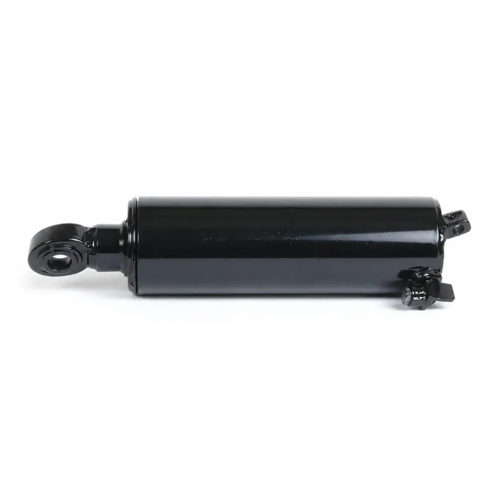
For example, some scissor lifts are fitted with maintenance safety struts, which must be reliably positioned in the specified locations in accordance with the model’s instructions. You must verify the permissible support load, engagement points and conditions of use; it must not be assumed that the maintenance struts can withstand the platform’s full load. Before entering the area beneath the lifting mechanism, the mechanical support and energy isolation specified by the manufacturer must be completed; the position of the hydraulic valve alone cannot fulfil this requirement.
During inspection, pay particular attention to whether locking components are in place and whether pins, retaining parts and bearing surfaces are damaged. Support components that are merely hung to the side without being properly engaged cannot be considered to have established support; wooden blocks, random steel pipes or jacks positioned in non-designated areas must not be used as substitutes for dedicated retaining devices.
Flow Controls That Limit Uncontrolled Descent
The descent speed is related to the rate at which oil is discharged from the cylinder. Throttle or flow control valves regulate movement by restricting the discharge of oil; pressure-compensated flow control devices can also minimise the effect of load pressure fluctuations on flow within a specified operating range. Pressure compensation can be understood as the automatic adjustment of flow conditions in response to pressure changes, but this does not imply that the speed remains completely constant under all operating conditions.
Standard speed control functions and burst protection functions should be verified separately. For example, if a speed control valve is mounted on a power unit distant from the cylinder port, a rupture in the hose between the cylinder and the valve may allow the hydraulic fluid to bypass this restriction and flow out directly. The fact that a platform descends smoothly during normal operation does not prove that it remains under control in the event of a hose rupture.
You can trace the oil return path of the load chamber on the schematic diagram to confirm which components the oil flows through during both normal descent and specified fault conditions. For multi-cylinder equipment, synchronisation requirements should also be checked; that is, how each cylinder maintains coordinated movement. It is not sufficient to simply set both speed control knobs to the same setting and assume that synchronisation will be maintained in the event of a fault on either side.
Position Sensors, Interlocks, and Emergency Stops
Position sensors inform the control system of the mechanism’s position; interlocks are control mechanisms that permit a specific action only when prescribed conditions are met. For example, operation may be prohibited if a door is not properly closed, or certain actions may be restricted once the mechanism reaches a specific position. Whether these functions are to be implemented and how the system should respond in the event of a fault should be determined by the equipment’s intended use and safety design; a standard position switch must not automatically be regarded as a complete safety system.
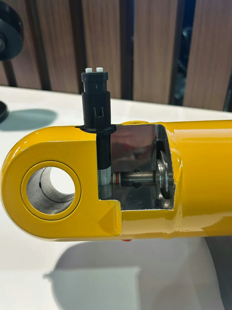
An emergency stop is used to issue a command to halt dangerous movements; however, the button itself does not bear any load, nor will it block a ruptured hydraulic hose. Whether the position can be maintained after the machine has actually come to a halt still depends on the valves, mechanical components and the entire control chain. An emergency stop is also not equivalent to energy isolation for maintenance; trapped pressure and gravitational loads may still be present after it has been pressed.
You should check the intended responses of the emergency stop, position limits and interlocks in accordance with the machine’s manual; should you discover that any protective measure has been bypassed or disabled, you must cease all related operations and rectify the issue. Do not bypass door locks, tilt limits or other safety conditions for the sake of temporary operation; after resetting the emergency stop, you must first verify the condition of the environment and the equipment before resuming operation in accordance with regulations.
What Happens During Hose, Pump, or Power Failure
First, identify which section has failed, then determine whether the protection mechanism can function effectively. A hose rupture may result in the sudden loss of sealing in the load oil circuit; a pump failure leads to a loss of oil supply capacity; whilst a power cut involves changes in the status of solenoid valves and the control system. These three scenarios cannot be summarised under a single conclusion.

a. Compare the Failure Scenarios
| Failure Scenario | Possible changes to the equipment | Protection conditions to be verified |
|---|---|---|
| Hose rupture in the load-bearing circuit | Hydraulic fluid may leak out through the rupture, causing the load to descend under the force of gravity | Whether the rupture is within the protection valve’s coverage range; whether the valve’s operating conditions and residual movement meet the requirements of the entire machine |
| Pump stops or loses the ability to supply oil | Normal lifting cannot usually continue, but the load will still exert force on the hydraulic cylinder | Whether the load-holding path can be maintained without pump supply, and whether the fault simultaneously affects other control conditions |
| Loss of electrical power or engine power | Normal drive ceases; valves and control systems enter their respective de-energised states | The de-energised position of the lowering valve, load-holding function, and whether an independent emergency power source or manual rescue path exists |
| Cylinder seal or internal passage leakage | Fluid may be redistributed between the two chambers; movement behaviour depends on the structure and circuit | It cannot be assumed that the cylinder port rupture valve will block internal leakage; further assessment should be carried out according to the model |
| Failure of one cylinder in a twin-cylinder system | The two sides may operate out of synchronisation, causing the platform to tilt or subjecting the structure to additional loads | The synchronisation of the entire unit, tilt limits and stop strategies must be verified; the two cylinders must not be examined in isolation |
For example, damage to the connecting fitting between the cylinder-end protection valve and the oil chamber constitutes a different fault location from a rupture in the hose on the outside of the valve. Inspection reports and procurement specifications should specify the extent of the protection provided, rather than simply stating ‘equipped with burst protection’. The protective action does not necessarily imply zero displacement; the system’s stopping or speed-limiting performance should be evaluated against the requirements for the complete machine.
b. Check the De-Energised State
For specific equipment, you should confirm how the flow path changes when de-energised by referring to the schematic diagram and valve documentation. A de-energised-closed lowering path may form part of a position-holding design, but valve sticking, external leakage or other faults must also be considered. One must not assume that the system will definitely lock in place after de-energisation simply because a solenoid coil is visible, nor should the de-energised state of all valves be assumed to be identical.
Similarly, the fact that a pump does not descend immediately after stopping merely reflects the system’s behaviour at that moment; it does not constitute verification of a hose rupture or valve failure. Do not attempt to test fault responses by temporarily disconnecting cables, severing hoses or loosening couplings.
c. Use the Model-Specific Recovery Procedure
Some equipment utilises manual emergency descent, backup power or a manual pump for recovery. Consult the manual for the relevant model and serial number range to determine the specific power source required, which locks must be released first, and the control position from which to operate.
If a mechanical lock is under load, it may not release immediately following a power failure; if a hose is already damaged, the standard power-off descent procedure may not be applicable. Trained personnel must assess the situation and carry out the prescribed rescue procedure; loosening the load-holding valve, disconnecting the hose or disengaging the safety mechanism must not be treated as a universal method of descent.
Inspection and Testing of Lift Fail-Safe Devices
Inspections should encompass pre-use visual checks, prescribed functional tests and specialist inspections. During external visual inspections, check for wear on hoses, leaks at couplings, loose valve blocks, whether mechanical retaining devices are in place, and whether labels and emergency operating instructions are clear. Where the equipment must be raised for inspection, first establish the support conditions specified for that model; do not enter hazardous areas held in place solely by hydraulic pressure.
Functional checks must be carried out by competent personnel using the loads, positions, areas and methods specified by the manufacturer. Do not cut hoses, loosen couplings under load, or ‘verify whether the valve will operate’ by lowering the safety settings. Regular inspections do not equate to the need for overload testing on every occasion; HSE explicitly advises that the necessity and method of testing should be determined by a professional assessment, as some overload tests may cause damage to the equipment.
Record the equipment and valve serial numbers, test basis, load and position, oil temperature, setting status, observations and arrangements for the next inspection. Should any bypassing of the protection system, abnormal descent or damage to critical components be detected, cease use immediately and address the issue. Following the replacement of safety-related valves, the rerouting of piping or modifications to the control system, revalidation must also be carried out as required; equipment must not be returned to service after merely performing a single no-load hoisting operation.
Why the Exact Safety Design Depends on the Lift Standard
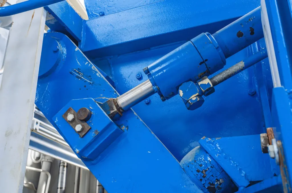
No single ‘hydraulic lifting cylinder standard’ can uniformly prescribe the safety configurations for all types of equipment. Passenger lifts, vehicle lifts, aerial work platforms and industrial lifting platforms differ in their intended use, mode of operation and associated hazards; it is therefore necessary to first determine the equipment category and the region of use, before checking the relevant standards and regulations.
1. Identify the Equipment Category First
The table below serves as a starting point for identifying applicable documents; it does not imply that all standards must be applied simultaneously to the same piece of equipment. Each standard has a specific scope of application and exclusions; selection cannot be based solely on the fact that the equipment ‘has a hydraulic cylinder and is capable of lifting’.
| Equipment or System | Common Standard Clues | What you should confirm first |
|---|---|---|
| Lifts and associated conveyance equipment within North American buildings | ASME A17.1/CSA B44 | Whether the equipment falls within the scope of the standard, and the version adopted by the local competent authority |
| Lifts for automotive maintenance and similar applications in North America | ANSI/ALI ALCTV | The scope of design, testing and verification for the complete unit; valve documentation cannot be used in lieu of certification for the complete unit |
| Vehicle lifts under the European standards system | EN 1493 | Whether the intended use and scope of the equipment comply with this standard; it should not be directly applied to man-riding aerial work platforms |
| Mobile aerial work platforms | North America: ANSI/SAIA A92.20; Europe: EN 280-1 | Region of use, method of man-riding operation and corresponding equipment classification |
| Lifts serving a maximum of two fixed landing levels under the European standards system | EN 1570-1 | Whether the actual landing method and intended use fall within the scope of this standard; this must not be generalised to apply to all goods lifts |
The hydraulic system itself may also be subject to general safety requirements such as ISO 4413; however, such documents cannot substitute for the complete equipment requirements of the specific lifting apparatus. In China and other markets, it is also necessary to verify the applicable local documents; the standards listed for a particular market in the table should not be treated as universally applicable rules.
2. Verify the Applicable Edition
The most recently published edition may not necessarily be the same as the edition that must be adopted for a project. For example, ALI has announced that ANSI/ALI ALCTV:2025 will come into force on 1 April 2027 and replace its previous edition. Based on the verification date of 22 October 2026 as per the information in this document, one cannot assume that the replacement has been completed merely because the ‘2025 edition’ is mentioned.
Lift regulations may also be adopted by local regulatory authorities at different times; the version actually applicable to the project must be verified. For example, the Government of Alberta publishes separately the lift regulations currently in force locally and their implementation dates; this verification step cannot be replaced directly by the latest catalogue from the standards publisher.
3. Prepare a Reviewable Safety Requirement
When confirming the design with the complete machine manufacturer or systems engineer, you may compile the following information to ensure that safety requirements are incorporated into the drawings and verification plan:
- Intended use of the equipment: Transporting people, goods or lifting vehicles; how the load is distributed; and whether anyone needs to work beneath the lifting components.
- Failure scenarios: Power failure, pump stoppage, which section of the piping may rupture, and the interaction between single and multiple cylinders.
- Protection locations and functions: Which device maintains position, which prevents abnormal descent, and which provides mechanical support during maintenance.
- Documentation and validation: The version of the standard adopted, hydraulic and control diagrams, component part numbers, inspection methods and acceptance criteria.
When discussing lifting cylinder configurations with GY Hydraulic, providing these specifications and installation drawings facilitates verification of interfaces and functions far more effectively than simply stating that ‘a safety valve is required’. The selection of hydraulic cylinders and valve assemblies should be aligned with the overall safety design of the machine, and validation must ultimately be carried out in accordance with the specific equipment.
FAQs-What Fail Safe Is Built Into The Hydraulic Lift Cylinders
Will a hydraulic lift fall if a hose bursts?
This cannot be determined solely on the basis of ‘hydraulic lifting’. If the rupture occurs within the range covered by the fitted safety valve, the system may stop or limit its descent as designed; however, if there is no protection, the installation position is unsuitable, or the valve fails to meet the activation conditions, dangerous movement may occur. You should verify the specific fault location against the machine’s validation documentation; normal position-holding behaviour must not be used as a substitute for assessing hose burst protection.
What is a hydraulic velocity fuse?
It is typically a hydraulic valve that detects abnormal flow and shuts off the corresponding circuit, used for specific line failure protection. It is not an electrical fuse, nor does it necessarily measure the platform’s speed directly. When selecting one, you should verify the trigger flow rate and installation direction; slow leaks or internal leaks within the cylinder that bypass the device may not necessarily trigger it.
How does a counterbalance valve hold a lift?
It restricts the outflow of load-bearing hydraulic fluid under the specified load-holding conditions and regulates the discharge of fluid once the appropriate control pressure is applied, thereby facilitating controlled movement of the load. Its performance depends on load pressure, pilot conditions, back pressure and installation position. In the event of slippage or oscillation during descent, the entire circuit should be inspected; do not attempt to eliminate the symptoms by altering the settings yourself.
Is a check valve alone enough for lift safety?
The presence of a check valve alone should not be considered sufficient. Whilst it may fulfil a specific function of preventing reverse flow, it does not automatically cover descent speed, all pipe rupture scenarios, maintenance support or control failures. The need for additional protection should be determined in accordance with equipment standards and risk assessments, rather than being concluded simply by adding a valve.
Can a hydraulic lift be lowered during a power failure?
Some equipment can be lowered using a dedicated emergency descent mechanism or backup power; in other cases, professional rescue is required. First, consult the power failure procedure for the relevant model and confirm whether there is a concurrent pipe failure, mechanical jam or load lock. Do not lower the platform by loosening pipes, draining oil or arbitrarily disengaging the load-holding device.
How often should hose-burst valves be tested?
There is no standard testing interval applicable to all hose-burst valves. Testing should be arranged in accordance with the requirements of the equipment and valve manufacturers, taking into account local inspection regulations and operating conditions. Routine visual inspections, periodic inspections of the entire unit, and specific functional tests of the hose-burst protection system are distinct tasks; the annual inspection cycle for a particular unit must not be directly applied as the trigger test interval for all hose-burst valves.
What is the difference between a safety prop and a hydraulic lock?
A safety prop provides support via a mechanical structure; a ‘hydraulic lock’ typically refers to a position-holding method that utilises valves to prevent the flow of hydraulic fluid, although this must be verified against the relevant drawings. The failure modes and intended uses of the two differ. When entering the area beneath a raised component for maintenance, you must use the mechanical support and isolation procedures specified for the equipment; you must not rely solely on the valves to maintain pressure.
Which standard governs hydraulic lift safety?
First, determine the equipment category and region. Car lifts, building lifts, aerial work platforms and lifting platforms each have their own applicable standards, and local regulations and inspection requirements may also apply. You should confirm the full standard number, version and basis of application with the equipment manufacturer, rather than searching for a single standard number that applies to all hydraulic lifting devices.
Choosing a Trusted Hydraulic Cylinder Manufacturer
From standard hydraulic cylinders to custom solutions, we help you improve equipment performance, delivery reliability, and batch consistency
Explore Rivmate Cases

Hey There, I'm Melody!
We are a hydraulic cylinder manufacturer. For over 20 years, we have focused on producing reliable hydraulic cylinders. Need a hydraulic cylinder solution? Feel free to contact us.