
Home / What Is a Locking Hydraulic Cylinder?
What Is a Locking Hydraulic Cylinder?
- Author: GY Hydraulic
- 20+ Years of Manufacturing
A locking hydraulic cylinder is a hydraulic cylinder assembly equipped with a dedicated locking or load-holding function, capable of restricting unintended movement of the output end under specified conditions. It may clamp the piston rod via a mechanical device, or rely on valves to control the flow of the hydraulic fluid. As the operating principles and safety limits differ between these two methods, one should not assume—simply because the term ‘locking’ is used—that it can immediately halt the load in any position or under any fault condition.
If you are searching for ‘What Is a Locking Hydraulic Cylinder?’, the most important question to ask first is: do you need to lock a load that has already come to a standstill, or to bring a moving mechanism to a halt? This GY Hydraulic guide will help you distinguish between mechanical locking and hydraulic load holding, understand the conditions for engagement upon pressure loss and release under load, and formulate requirements for holding force, control sequences and functional checks that can be verified.
Table of Contents
What Makes a Hydraulic Cylinder a Locking Cylinder?
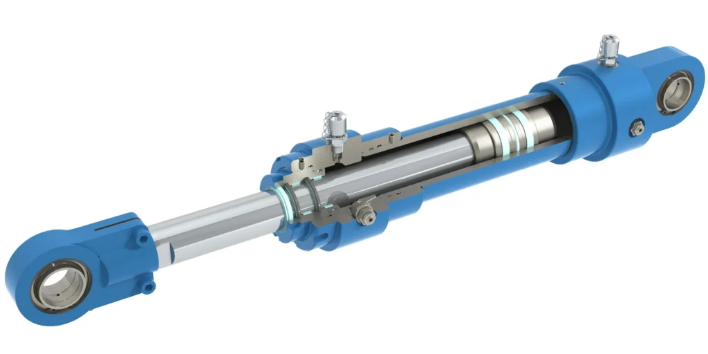
A standard hydraulic cylinder converts hydraulic pressure into linear thrust or pull, whilst the piston rod is the component that extends from the cylinder body and connects to external mechanisms. Whether it can maintain its position after the oil supply is cut off depends on the load, the valves, the leakage paths and the circuit as a whole. The fact that it remains stationary for a time does not mean that it possesses a defined and verified locking function.
When referring to a device as a ‘locking hydraulic cylinder’, you must be able to confirm at least three things: what mechanism restricts movement, under what conditions it engages, and what load it is permitted to hold. Mechanical locks may be fitted to the hydraulic cylinder or may form a separate component within the assembly; hydraulic load holding is achieved by specialised valves that restrict the outflow of the load-bearing fluid. These details must be clearly specified in drawings and technical specifications; the term ‘locking’ alone is insufficient.
For example, where a vertically mounted cylinder is required to stop at a specific working position, you should first confirm where the locking device is fixed, through which connecting components the load is ultimately transmitted to the frame, and whether it restricts movement in one or both directions. If a product is mechanically locked only at a specific end position, it cannot be used directly for locking at any position throughout its full stroke. When requesting a quotation, it is more effective to specify the position, the direction of the force and the expected state in the event of failure, rather than simply asking “Do you have self-locking cylinders?”.
Compare Mechanical Rod Locks and Hydraulic Load Holding
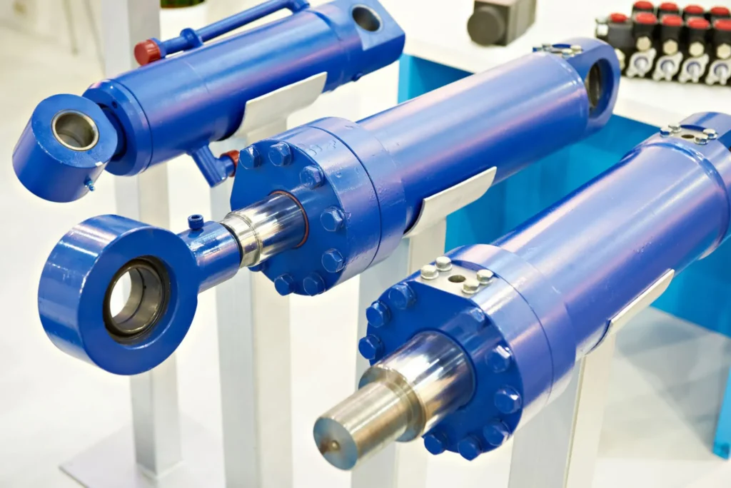
Follow the Mechanical or Hydraulic Holding Path
Mechanical rod locks form a mechanical load-bearing relationship with the rod via a clamping sleeve, a wedging mechanism or other designs. A clamping sleeve can be understood as a component that surrounds the rod and generates a clamping force, whilst wedging utilises an inclined surface to convert the applied force into a stronger clamping action. Specific designs may rely on friction for retention or employ mechanically constrained engagements; not all mechanical locks should be regarded as the same type of device.
Hydraulic load holding restricts the flow of hydraulic fluid via valves. The piston is the component within the cylinder that, under hydraulic pressure, drives the movement of the rod; when the load pushes against the piston, hydraulic fluid would normally need to flow out of the corresponding chamber. By closing this path, the valve restricts movement under the specified design conditions. However, this load-bearing path still comprises the hydraulic cylinder, valve, connecting components and the contained hydraulic fluid; it should not be interpreted as the rod being mechanically jammed.
| Comparison | Mechanical Rod Lock | Hydraulic Load Holding |
|---|---|---|
| Holding Principle | Transfers the load from the rod to the lock body and mounting structure via mechanical contact | Restricts the outflow of hydraulic fluid carrying the load through a specified path |
| Key Inspection Points | Holding force, load direction, rod surface requirements, engagement and release conditions | Valve function, leakage, installation position, opening and pressure protection conditions |
| In the Event of Pressure Loss | Depends on the engagement principle and release circuit; cannot be generalised | Depends on the valve’s state, the location of the rupture and the remaining oil passages |
| Motion control | Static rod locks cannot, by default, perform braking or descent speed regulation | Valves and circuits capable of performing the relevant motion control tasks must be selected |
| Accuracy and displacement | Engagement displacement, clearance and structural deformation must still be verified | Performance will still be affected by factors such as hydraulic fluid compression, temperature and leakage |
For example, where a workstation requires the rod position to be held for an extended period, a mechanical rod lock may be considered; whereas when the load requires a smooth descent, hydraulic motion control must also be addressed. The two functions can be combined, but whether they need to be configured simultaneously should be determined based on specific failure risks and equipment requirements, rather than simply adding components.
Distinguish Holding Valves from Lowering Control

A hydraulically controlled check valve is a valve that, whilst preventing reverse flow, can be opened by applying a control oil pressure; this control oil pressure is also known as pilot pressure. They can be used for position holding, but one should not assume, on this basis alone, that once opened, they can smoothly control a descent driven by gravity.
Balancing valves can be used to control movement driven by the load itself, helping to limit oil discharge on the load-bearing side so that the descent movement is synchronised with the oil supply conditions. You should verify ‘position holding when stopped’ and ‘how movement occurs after initiation’ separately; these two types of valve should not be treated as interchangeable locks. Manufacturers’ technical documentation also clearly distinguishes between the position-holding function of hydraulically controlled check valves and the load motion control function of balancing valves.
The valve’s location is equally important. For example, if there is still an unprotected hose between the valve and the cylinder, the load cannot be considered protected solely on the basis that ‘the system is fitted with a holding valve’ should that section of hose rupture. You should verify the load oil circuit against both the schematic diagram and the actual installation, rather than relying solely on component names.
Understand Spring-Applied and Pressure-Released Operation
A spring-applied, pressure-released mechanism is a common operating principle for mechanical rod locks: the force stored in the spring engages the clamping mechanism; once the release port reaches the specified pressure, the internal mechanism overcomes the spring force, allowing the rod to move. The release medium may be hydraulic oil or compressed air; it must be used in accordance with the specific model and must not be interchanged arbitrarily. There are also designs that rely on pressure to apply clamping force; therefore, this operating principle cannot be applied to all locking cylinders.
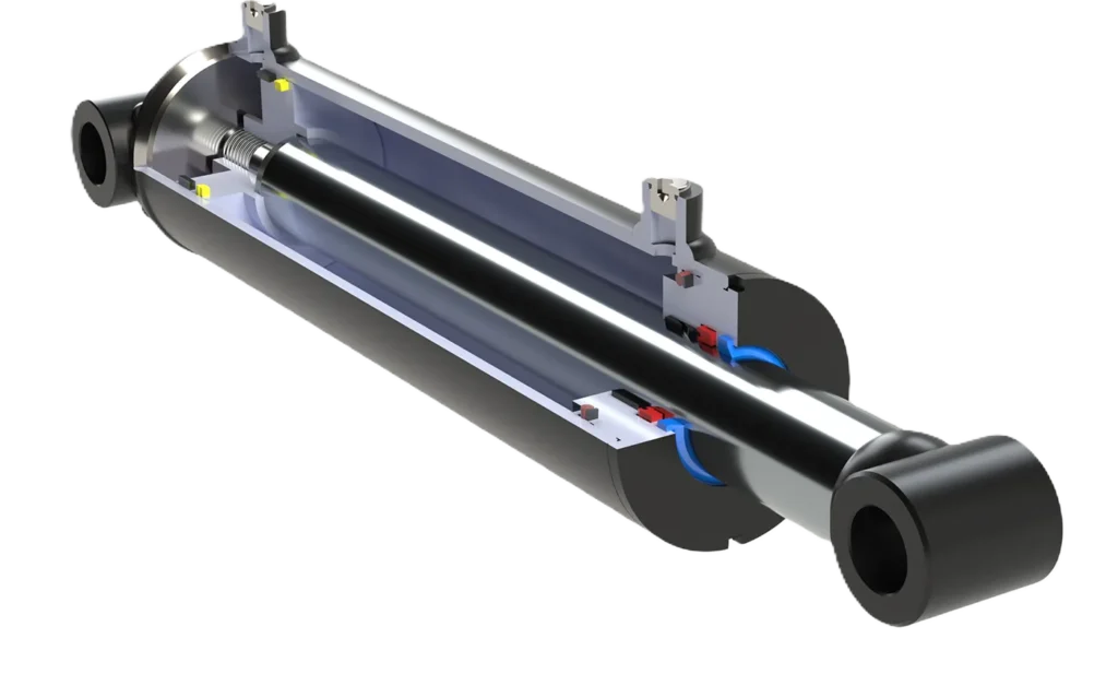
The disappearance of release pressure is not the same as the loss of power to the equipment. If, following a power cut, the valve still traps pressure within the release chamber, the spring lock may not engage immediately; if it takes time for the pressure to drop, there will also be a delay in response. You should verify the position of the control valve during a power cut, the pressure relief path of the release chamber, and whether residual pressure might impede locking; you must not rely solely on the term ‘spring lock’ to judge the effect of a power cut.
For example, when a vertical mechanism is preparing to resume movement, before the release rod locks, the drive side or other load-bearing device must reliably take over the load in accordance with the approved control design to prevent sudden sinking after unlocking. Different clamping principles have different requirements for unloading, retraction and release; ‘applying pressure to the release port’ cannot be regarded as a complete procedure that ensures safe load-bearing opening for all models.
Distinguish Static Holding from Dynamic Emergency Stopping
Check Whether the Device Holds or Brakes
Static holding refers to a situation where a load is borne after the member has come to a standstill and meets the specified connection conditions; dynamic emergency braking, on the other hand, involves decelerating a moving mass to a standstill whilst absorbing or transferring kinetic energy. A device capable of holding a static load is not necessarily capable of bringing that load to a standstill.
| Task | Static holding | Dynamic emergency braking |
|---|---|---|
| State at Engagement | The component is typically required to be at rest; specific requirements depend on the model | The load is still in motion |
| Key Verification Points | Permissible load, direction, engagement conditions, possible displacement | Moving mass, velocity, response time, braking force and permissible stopping distance |
| Energy considerations | Focus is on sustained load-bearing and position holding | Must also handle kinetic energy and energy continuously input during braking |
| Frequency of use | To be used in accordance with permitted duty cycles | Emergency braking capability does not imply that it is permitted to use it for stopping in every cycle |
For example, a static rod lock can maintain its position once the clamping plate has come to a standstill, but directly commanding it to clamp whilst the clamping plate is moving downwards may result in varying levels of impact and wear. You should verify whether the manual explicitly permits dynamic engagement, as well as the permitted speeds, load directions, frequency of use and post-operation inspection requirements. Some products permit occasional emergency braking under specified conditions, whilst others are intended solely for static clamping; this cannot be inferred from the product name alone.
Include Energy and Response Distance
Kinetic energy is the energy possessed by an object due to its motion, calculated using the formula E = ½mv², where m is the mass in motion and v is the velocity. Assuming a mass of 600 kg and a velocity increasing from 0.2 m/s to 0.4 m/s, the kinetic energy increases from 12 J to 48 J; J is the unit of energy, the joule. This is merely a theoretical example illustrating that doubling the velocity quadruples the kinetic energy; it does not represent test data for any specific locking device.
In actual emergency stop scenarios, one must also account for the time required for control detection, valve switching, depressurisation of the release chamber and mechanical engagement. The vertical load may continue to descend during this period, whilst gravitational force, hydraulic driving force and mechanical elasticity may continue to impart energy during the braking process. Consequently, comparing a single static holding force value alone will not yield the actual stopping distance.
You may specify the maximum moving mass, the worst-case speed, the direction of movement, the permissible stopping distance and the emergency braking scenarios in the technical requirements, so that the supplier and the original equipment manufacturer can jointly verify these parameters. Do not attempt to upgrade a standard static lock to an emergency stop brake on your own, nor should you test its ability to catch the load by suddenly cutting off the pressure whilst the load is under load.
Select Holding Force, Release Pressure, and Engagement Conditions
Calculate the Load That Actually Reaches the Lock
Holding force is the axial force that a device can withstand under specified conditions to restrict the movement of a member. Axial refers to the direction along the length of the member. When selecting a model, one must not only consider the weight of the load, but also analyse external process forces, the transmission geometry, and any forces that the hydraulic cylinder may continue to exert whilst locked; forces acting in different directions should be combined according to actual operating conditions and must not simply be added together without regard to direction.
The following is a set of hypothetical operating conditions; these are not product ratings or recommended configurations: the hydraulic cylinder is mounted vertically, with the rod extending downwards, supporting a 600 kg load suspended below, and a cylinder bore of 50 mm. The cylinder bore refers to the internal diameter of the cylinder barrel. If the rodless chamber—that is, the side of the piston without a rod—can still achieve a pressure of 20 MPa during locking, and the pressure in the other chamber is temporarily disregarded, this hydraulic pressure will also push the rod downwards. For gravity calculations, the acceleration due to gravity is taken as g = 9.81 m/s².
| Assumed Force | Theoretical Calculation Result | Implications for Selection |
|---|---|---|
| Gravitational force of a 600 kg load | Approx. 5.9 kN | This is the axial force generated by weight; it is not the total possible load |
| Thrust across the full cross-sectional area of a 50 mm bore at 20 MPa | Approx. 39.3 kN | If this pressure is still permitted to act during locking, its effects must be analysed |
| Both acting simultaneously in the same direction, disregarding other factors | Approx. 45.2 kN | Indicates that selecting a lock based solely on the load’s weight may significantly underestimate requirements |
Where 1 kN (kilonewton) = 1,000 N, and MPa (megapascal) is the unit of pressure, with 1 MPa = 1 N/mm². The table does not account for friction, impact, the weight of other moving parts or design margins; the figure of 45.2 kN must not be taken directly as the final holding force rating to be procured. The design should first be reviewed to identify which forces may be present simultaneously, and selection should then be made based on the device’s permissible values and the overall equipment requirements; a single multiplier applicable to all equipment should not be applied indiscriminately.
Verify Release Pressure at the Device
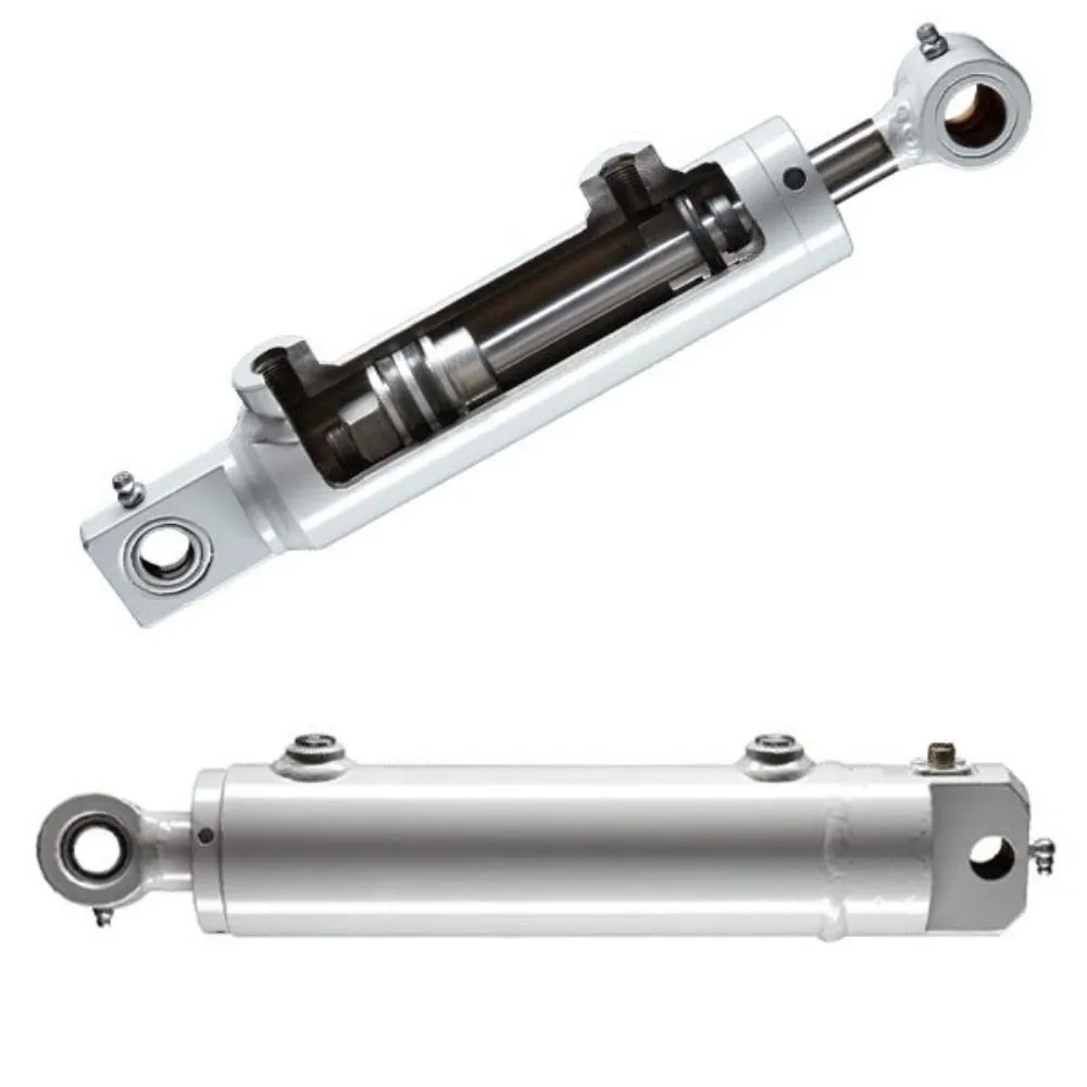
Release pressure is the pressure required to allow the locking mechanism to reach its permitted state of movement; it is not the working pressure of the hydraulic cylinder, nor is it the device’s permissible holding force. You must simultaneously verify the minimum release requirements, the maximum permissible pressure, the permissible media, the pressure relief conditions, and whether the device can withstand the specified load during unlocking.
For example, sufficient pressure at the pump station does not guarantee that the release port will reach the required pressure in a timely manner when long piping, low temperatures or other simultaneous operations are present. Pressure present on the return or vent sides may also affect the engagement and release of certain devices. You should request verification of the actual conditions at the device’s interfaces, rather than relying solely on the pump’s nameplate values; even if pressure readings meet the requirements, this does not automatically constitute confirmation that the device has been ‘fully released’.
Match Direction, Rod Surface, and Engagement Conditions
It is also necessary to confirm whether the device is designed for unidirectional or bidirectional loading, whether engagement is permitted at any position along the stroke, and whether a small amount of displacement is required after engagement to establish full load-bearing capacity. Two clamps fitted onto a rod of the same diameter may have different requirements.
The rod diameter and its permissible dimensional tolerances, surface hardness, surface roughness, coatings and lubrication conditions may all affect clamping performance; Surface roughness refers to the degree of minute irregularities on the rod’s surface. Suitability should not be judged solely on the basis that ‘the rod surface is very smooth’, nor should the rod surface be ground or the lubrication method altered to increase friction. For example, when fitting a rod lock, the supplier should be asked to confirm the original rod’s surface and material conditions, rather than simply providing a diameter. Temperature, dust and corrosive environments should also be included in the quotation request.
Integrate Controls, Position Feedback, and Failure Responses
Confirm Load Transfer Before Releasing
The locking device must be coordinated with the drive and load-holding circuits; it must not be connected to a single switch alone. For designs requiring static engagement, the control system must verify that the mechanism has met the engagement conditions before allowing the lock to assume the load in accordance with specifications; when resuming movement, it must first be ensured that the load is reliably supported before releasing the lock, and movement must only be permitted once release has been confirmed. The specific supply pressure and valve switching sequence shall be determined by the design of the corresponding device and the complete machine.
For example, if the lock is already bearing a vertical load and the cylinder chamber pressure changes following a dwell period, direct unlocking may cause the mechanism to sag. What is required is not simply extending a timer, but verifying how the load is transferred, how the release conditions are established, and how safety is maintained in the event of an anomaly. The technical specifications for the accompanying control block also include load transfer and smooth start-up after unlocking as design considerations.
Distinguish Position Feedback from Lock-State Feedback
Feedback refers to the transmission of actual status from a sensor back to the control system. A rod position sensor indicates how far the rod has moved; a locking or release sensor, on the other hand, indicates the corresponding state of the lock’s internal mechanism. The two are not interchangeable; a locking command issued by the controller does not necessarily mean that the mechanical device has established load-bearing capacity.
| Signal or Check | Information Provided | What Cannot Be Proven Independently |
|---|---|---|
| Rod Position Feedback | Current rod position and its changes | Whether the rod lock is engaged and possesses the required holding capacity |
| Locking or Release Status Signal | Whether the corresponding detection position has been reached | Full holding performance under actual load |
| Pressure feedback | Pressure conditions at the detection point | That all mechanical components have moved into position, or that pressure is uniform across all isolated sections |
| Specified load-bearing function test | Holding performance or related operational behaviour under test conditions | Protection against all faults beyond the scope of the test |
For example, if the interface displays ‘Locked’ but the rod position continues to change, this should be handled in accordance with the equipment fault procedure; production must not continue simply because the indicator light is illuminated. Whether a signal requires diagnostics, redundancy and a specific safety control architecture must be determined by a whole-machine risk analysis; it is not permissible to claim that the entire machine meets a certain safety level based solely on a standard proximity switch.
Define the Response to Each Failure
Fail-safe refers to entering or maintaining the intended safe state under specified fault conditions; it does not mean that the equipment remains absolutely stationary in the event of any fault. At a minimum, the behaviour in the event of power failure, insufficient pressure supply, release line failure, control valve sticking, feedback anomalies, and restart must be analysed. If the equipment requires an emergency stop, the entire response chain must be verified, rather than relying solely on the mechanical capabilities of the lock.
You may request that the designer provide a table detailing ‘Failure – Detection Method – Equipment Response – Recovery Conditions’. For example, if a full release signal is not received within a specified time, movement should be halted and an alarm triggered in accordance with a validated strategy; if the mechanism is still in motion, the stopping measures taken must be commensurate with the dynamic capabilities of the device. Upon power restoration, a load-bearing lock must not be automatically released simply because the signal reappears, without a status check being performed. The manufacturer’s documentation also explicitly states that the locking component itself cannot constitute a complete safety solution for the entire machine.
Match Locking Designs to Lifting, Clamping, and Positioning
With regard to lifting mechanisms, the key considerations are gravitational loads, permissible displacement following a loss of pressure, load transfer and emergency recovery. For example, if a lock is only designed to withstand loads in a specified downward direction, it cannot be assumed that it can also withstand process thrust in the opposite direction; if smooth descent is required, the hydraulic motion control must be verified separately, rather than treating the rod lock as a flow control valve.
For clamping fixtures, a distinction must be made between maintaining position and maintaining clamping force. Workpieces, frames and connecting components are subject to elastic deformation, whilst temperature changes or settlement of contact surfaces may also alter the clamping force; even when the rod position is locked, the force acting on the workpiece is not necessarily constant. For instance, at machining stations where a constant clamping force must be maintained, the minimum workpiece clamping force and the method of verification must be clearly specified; it is not sufficient to provide only the holding force of the lock as proof.
For positioning mechanisms, it is necessary to verify engagement displacement, clearance, stiffness and external loads; Stiffness refers to a mechanism’s ability to resist deformation under load. For example, rod locks are suitable for helping to maintain the position of a shaft under specified conditions, but whether they can meet the requirements for precision positioning also depends on the deformation of the entire mechanism and feedback control. When submitting requirements to GY Hydraulic, it is recommended to specify the intended use, positional error requirements, direction of force, operating cycle, pressure supply conditions, and whether dynamic emergency braking is involved, before selecting a specific locking structure.
Plan Inspection and Manufacturer-Specified Functional Tests
Visually sound condition and normal indicator lights are no substitute for the functional tests specified by the manufacturer. The inspection plan should be determined in conjunction with the model manual, cycle count, load, environment and whether emergency braking has ever occurred; inspection intervals or test multipliers should not be devised uniformly for all locks. For example, certain devices have specific inspection requirements following emergency braking, overload or maintenance; these should be treated as conditions for recommissioning, rather than simply waiting for the next scheduled maintenance.

You may include scratches and contamination on the actuator surface, loose mounting components, connections and leaks, locking and release signals, as well as abnormal bounce after unlocking in the inspection records. Functional tests should specify the test load, direction, position, hold time, permissible displacement, personnel isolation and backup protective measures, and must be carried out by competent personnel in accordance with approved procedures. Manufacturers’ documentation requires periodic performance checks, with specific methods set out in the relevant operating manual; a single factory pressure test must not be used as a substitute for in-service inspections.
Should slippage, incomplete release, abnormal scuff marks or inconsistencies between feedback and operation be detected, the relevant function must be deactivated in accordance with procedures and an inspection arranged. Do not conduct so-called ‘failure tests’ by abruptly cutting off the loaded piping, nor should spring-preloaded locking mechanisms be disassembled without authorisation. Prior to maintenance, the load must still be secured, the power source isolated and residual pressure verified; the engaged state of the locking mechanism does not indicate that hydraulic and spring energy have been dissipated.
FAQs
Does every locking cylinder remain locked after power loss?
No. It depends on the locking mechanism, the state prior to the power failure, and whether the control valve allows the pressure in the release chamber to drop as designed following a loss of power. For example, a spring-engaged device may not lock immediately if the release chamber remains pressurised; structures that rely on pressure for clamping have different requirements. You should check the power-off response and verification records for the entire machine; do not rely solely on product descriptions such as ‘normally closed’ or ‘locks on pressure loss’.
Can a locking cylinder hold at intermediate positions?
Some can. Devices suitable for continuous clamping along the rod surface may maintain an intermediate position within the permitted stroke, whilst end-position locking or specific mechanical engagement mechanisms may only permit locking at designated positions. For example, where equipment requires holding at multiple workstations, you should confirm the permitted locking range, engagement conditions and engagement displacement; do not use a cylinder capable of locking at the end positions directly for holding at arbitrary positions.
Can a locked cylinder still contain stored hydraulic pressure?
Yes. Mechanical locking does not automatically drain the cylinder chamber; fluid isolated by valves or accumulators may still store energy; accumulators are components designed to store hydraulic energy. For example, opening a fitting after locking the rod may still result in fluid spray or load redistribution. You should depressurise the equipment in accordance with the operating procedures and verify the relevant sections; safety cannot be determined solely by a single reading from a lock indicator or the pump outlet pressure gauge.
Can a rod lock be fitted to an existing cylinder?
This is possible for some units, but compatibility must be verified. In addition to the rod diameter, you must check the rod surface material and finish, tolerances, concentricity, required rod length, installation space, and the load-bearing path from the lock body to the frame. For example, retrofitting may reduce the available stroke, or require a longer rod and a new mounting structure. You should have the supplier review the original cylinder drawings, load specifications and control circuit; you cannot simply purchase a lock sleeve of the same diameter and fit it onto the cylinder.
Is a rod lock a substitute for maintenance supports?
It cannot be assumed to be a substitute. During maintenance, the control circuit may be disconnected, the release mechanism accidentally triggered, or load-bearing components removed; the mechanical supports, locking devices and energy isolation specified by the equipment manufacturer must still be implemented. For example, before personnel enter the area beneath a raised press plate or platform, reliable protection must be established in accordance with specific maintenance procedures. A device may only be used in accordance with a maintenance plan for the entire machine if its relevant application has been explicitly specified and verified within that plan; operators must not arbitrarily assume that a rod lock serves as a maintenance support.
Can a lock release under full load?
This depends on the model and the complete load transfer procedure. Some devices permit release under the specified load, whilst others require the load on the lock to be removed first, or a small reverse movement to be carried out in accordance with the procedure; simply increasing the release force is not sufficient. For example, when a lock is bearing a vertical load, even if it can be opened whilst under load, the drive must be prepared to take over the load to prevent sudden dropping. You must confirm separately whether ‘the device can be opened’ and ‘who will bear the load after opening’.
Does a load-holding valve eliminate all cylinder drift?
This cannot be guaranteed. Drift refers to unexpected displacement that occurs when a position is to be held; it may be caused by factors such as valve leakage, internal cylinder leakage, changes in hydraulic fluid temperature, compression effects and mechanical deformation. Whether internal leakage causes continuous movement also depends on the direction of the load and other hydraulic pathways. For example, if slow movement persists after installing a load-holding valve, the cause should be investigated on a circuit-by-circuit basis; one cannot simply assume the valve is faulty based on drift alone, nor can it be guaranteed that replacing the valve will result in permanently zero movement.
Are locking cylinders suitable for personnel lifting by default?
No. The presence of a locking function merely indicates that the equipment may be capable of performing certain holding or protective tasks; it does not directly prove that the entire machine is suitable for lifting personnel. Lifting personnel requires an assessment of the machine’s overall structure, fault protection, control systems, emergency rescue procedures and the applicable requirements of the location of use. For example, even if a rod lock is fitted to a goods-lifting mechanism, this modification alone does not permit its conversion into a personnel platform. The specific intended use and supporting documentation must be confirmed by the person responsible for the machine’s design and compliance, rather than being determined solely by the name of a component.
Choosing a Trusted Hydraulic Cylinder Manufacturer
From standard hydraulic cylinders to custom solutions, we help you improve equipment performance, delivery reliability, and batch consistency
Explore Rivmate Cases

Hey There, I'm Melody!
We are a hydraulic cylinder manufacturer. For over 20 years, we have focused on producing reliable hydraulic cylinders. Need a hydraulic cylinder solution? Feel free to contact us.