Home / Hydraulic Cylinders for Log Splitters: How to choose Hydraulic Cylinders for Log Splitters
Hydraulic Cylinders for Log Splitters: How to choose Hydraulic Cylinders for Log Splitters
- Author: GY Hydraulic
- 20+ Years of Manufacturing
When selecting a hydraulic cylinder for a log splitter, first make sure it fits and operates correctly, then calculate the thrust and speed. Even if two cylinders are labeled with the same stroke and “tonnage,” they may not be interchangeable due to differences in mounting center distance, port configurations, or return mechanisms. Conversely, installing a cylinder with a larger bore may increase thrust at the same pressure, but it will require the pump to deliver more fluid, which may slow down the operation.
If you’re comparing hydraulic cylinders for log splitters, the most useful information you have on hand is the equipment model, the original cylinder part number, mounting dimensions, and hydraulic circuit details. Below, we’ll walk through the actual verification process for replacement: how to filter out incompatible candidates based on the original cylinder’s specifications, how to estimate the output force and time required for the splitting action, and what specifications to clearly specify when requesting a quote.
Table of Contents
Match Cylinder Mounts, Pin Sizes, and Retracted and Extended Lengths
Measure from the Mounting References
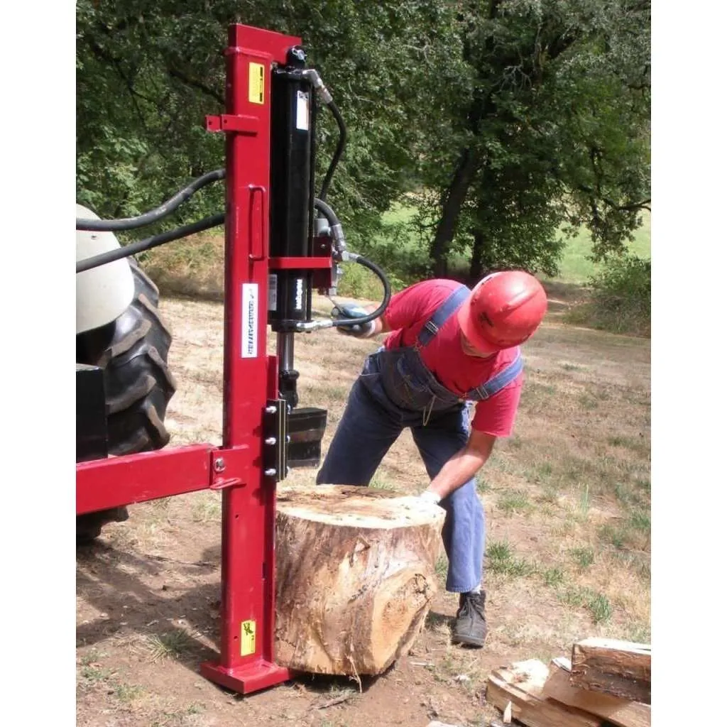
First, check how the equipment is connected to both ends of the cylinder, then decide where to measure the length. For hydraulic cylinders mounted on pins at both ends, the fully retracted and fully extended lengths typically refer to the distance between the centers of the two mounting pins in their respective states, not the distance measured from one end of the cylinder body to the tip of the piston rod. The piston rod is the component that extends from the cylinder body to drive the movement of the splitting wedge or push plate. Other mounting configurations should be verified against the reference plane or axis specified in the drawings, and the positions at both ends should be recorded using the same set of reference points.
| Mounting Type | What to Use as Length Reference | What Else to Verify |
|---|---|---|
| Both ends connected by pins, such as fork lugs, single lugs, or cross tubes | Centerlines of the mounting pins at both ends; for fork lugs, the U-shaped ends that clamp the intermediate connecting member | Diameters of pins and pin holes, or inner diameters of bushings; inner width of fork lugs or width of single lugs and cross tubes; method of securing the pins |
| Cylinder body side trunnion, rod-end pin connection | Use the centerline of the trunnion on the cylinder body and the centerline of the pin hole at the rod end as references; verify the axial installation distance according to the drawing | The trunnion is a lateral support shaft that allows the cylinder body to swing; verify its diameter, the distance between the two supports, and the swing clearance |
| Flange mounting, with rod end connected to a push plate or connecting rod | Measure from the mounting surface where the flange contacts the frame to the center of the rod-end pin hole or the connection surface specified in the drawing | Flange hole positions, bolt and positioning dimensions, rod-end interfaces, and interference during extension and retraction |
Check Both End Positions on the Machine
The same stroke does not necessarily mean the same installation length. For example, suppose two candidate cylinders both have a stroke of 500 mm, but the fully retracted center-to-center distance of the new cylinder is 50 mm longer than that of the old one. If the mounting points at the cylinder base remain unchanged and the cylinders are arranged in a straight, coaxial configuration, both the fully retracted and fully extended positions of the rod ends will shift forward by 50 mm. This could reduce the space available for loading lumber or cause the push plate to contact parts at the other end that it should not. The fact that a pin can pass through does not prove that the fork ear width, guidance, and the entire range of motion are suitable.
You can mark the “bottom pin center,” “rod end pin center,” and “installation width” on a photo of the original cylinder, compare these with the dimensions at both ends from the original manufacturer’s drawings, and then overlay the candidate cylinders onto the same installation diagram for verification. Record whether the cylinder makes contact with guide rails, brackets, hoses, or protective components throughout the entire stroke. Give priority to original factory dimension drawings and existing records; if on-site measurements are necessary, have qualified personnel follow equipment procedures to ensure power isolation, residual pressure relief, and support for moving parts, and do not take measurements near moving splitting wedges or push plates.
Check Bore, Stroke, and Rod Diameter Against the Original Cylinder
After obtaining the original cylinder drawings, record the three dimensions separately. The piston is the component inside the cylinder that moves under hydraulic pressure and drives the piston rod. Bore diameter refers to the inner diameter of the cylinder barrel, which determines the total effective area of the piston; stroke is the distance traveled by the moving part from fully retracted to fully extended; rod diameter is the diameter of the protruding piston rod, which affects pressure stability and the effective area available during retraction. The outer diameter of the cylinder barrel includes the wall thickness; therefore, the outer shell diameter measured with calipers cannot be used as a substitute for the bore diameter. The length of the exposed rod is also not the same as the stroke.
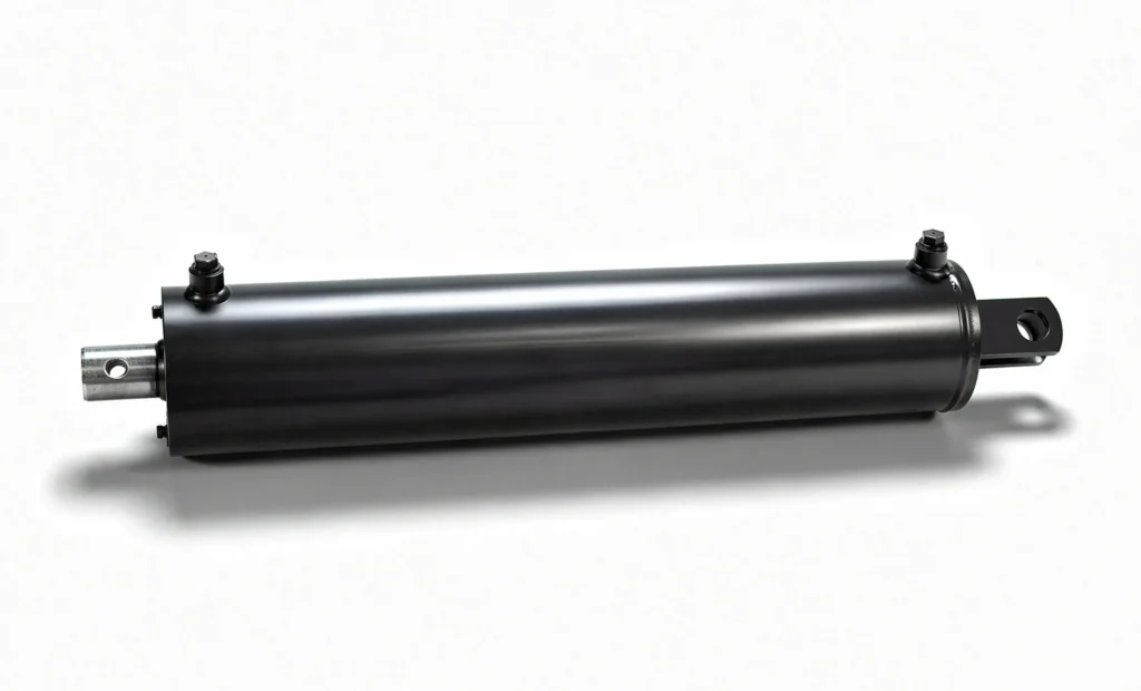
- Bore Diameter: Prioritize consulting the drawings or specifications corresponding to the original part number. Even if two cylinder bodies appear to be the same thickness, their wall thicknesses may still differ.
- Stroke: For the same pair of mounting reference points in linear motion, verify the stroke by subtracting the fully retracted length from the fully extended length shown on the drawing. The actual length of wood that can be placed between the split wedge and the push plate also depends on the equipment’s end positions and clearances.
- Rod Diameter: Verify the dimension indicated on the drawing or the diameter of the exposed rod under safe operating conditions, and confirm the rod-end threads, pin holes, or push plate connections. Under compression during long strokes, the rod may also buckle—that is, the slender member may lose stability and bend sideways—so verification based on installation and load conditions is required.
For example, simply switching to a longer stroke to split a slightly longer length does not automatically increase the machine’s total allowable log length; the new end position may first encounter the equipment’s limit stop, and the stability of the rod will also change when it extends further. Replacing parts according to the original specifications and upgrading by changing dimensions are two distinct matters. Whenever the cylinder bore, stroke, or rod diameter is altered, the installation, load conditions, and return stroke must be re-verified—not merely checking whether the cylinder can be secured to the frame.
Verify Hydraulic Port Threads, Sizes, and Locations
Oil ports are the connections between the cylinder and oil lines or valves that allow fluid to enter and exit. When taking notes, do not simply write “two 1/2-inch oil ports”; instead, list the thread type, nominal size, sealing method, position, and orientation separately. The nominal size is the designation for the connection specification and does not necessarily equal the actual diameter you measure. Place the connection diagrams of the old cylinder and the candidate cylinders side by side, and check each port individually at both the cylinder end and the hose fitting end to avoid judging compatibility based on how many turns an old fitting can be screwed in.
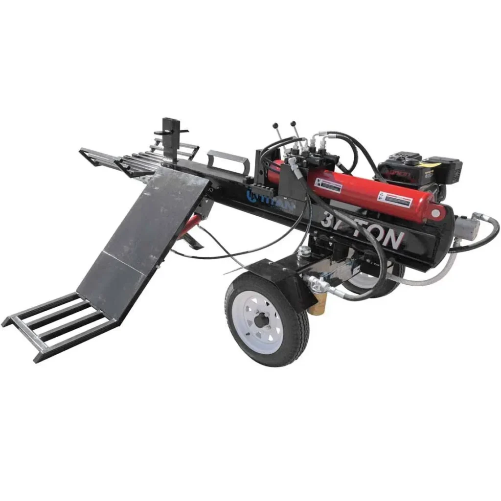
For example, NPT tapered pipe threads and BSPP straight pipe threads, both with a nominal size of 1/2, are not directly interchangeable ports. Tapered threads have an axial taper, while straight threads have a diameter that remains essentially constant; the specific sealing location must be confirmed based on the fitting design. Even if the threads on new and old cylinder ports are identical, if the new port faces the frame, the elbow and hose may be pinched throughout the full stroke.
When requesting a quote, include a photo and drawing for each port, with annotations such as: “Cylinder bottom end: Thread type and nominal size ___; Sealing method ___; Orientation as seen from the specified angle ___.” . If the model is unknown, mark it as “to be confirmed,” and have the supplier verify it based on dimensional drawings or appropriate identification methods. If an adapter is required, also verify the pressure rating, flow capacity, and hose routing of the connection; do not force an unknown fitting into place just to make the installation work.
Check Cylinder Operating Type, Pressure Rating, and Calculated Splitting Force
Match the Action and Pressure Limits First
A double-acting cylinder is a hydraulic cylinder driven by hydraulic pressure during both extension and retraction. A single-acting cylinder is driven by hydraulic pressure in only one direction, while the other direction relies on a spring, gravity, or other external forces. For log splitters that originally used hydraulic power to actively retract the splitting wedge or push plate, you should first verify the condition of the old cylinder, directional control valve, and return function; do not replace them with a design that relies solely on external forces for return. A directional control valve directs hydraulic fluid to different chambers to change the direction of motion; check the machine’s manual to verify whether it has an automatic return function and how the control lever returns to the “stop” position after the return stroke is complete.
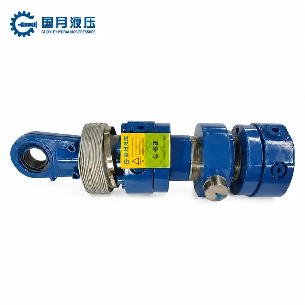
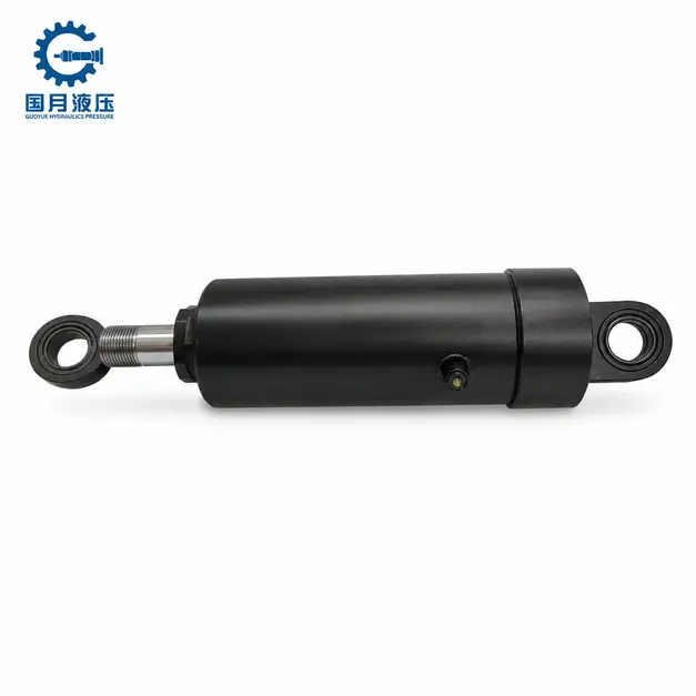
The rated operating pressure is the pressure at which the cylinder is permitted to operate under the manufacturer’s specified conditions; actual operating pressure will vary depending on the resistance of the wood and the condition of the pump and valves. A relief valve is used to limit the pressure in the circuit it protects; its set point does not represent the cylinder port pressure for every stage of operation, nor should it be used as a substitute for inspecting hoses, fittings, valves, and mounting components. For example, while a new cylinder may withstand higher pressure, this does not automatically result in greater splitting force for the original machine; nor should the pressure of the original machine be adjusted without authorization in pursuit of higher tonnage.
Estimate Extension Force from Pressure and Area
For a common single-rod, double-acting cylinder, when oil is supplied from the rodless chamber, first estimate the force using F = P × A. The rodless chamber is the side of the cylinder where the piston has no rod; here, A = π × cylinder diameter² ÷ 4, and P should be the pressure in that chamber under the corresponding operating conditions. When pressure is expressed in MPa (megapascals) and area in mm², the result is in N (newtons), since 1 MPa = 1 N/mm²; 1 kN (kilonewton) = 1,000 N.
Hypothetical Example: Cylinder bore diameter 100 mm, rod diameter 50 mm, and rodless chamber pressure 16 MPa. The total cross-sectional area is approximately 7,854 mm². Assuming the pressure on the rod side is approximately zero and neglecting friction for now, the theoretical extension force is approximately 125.66 kN. In actual operation, when oil discharge is obstructed, back pressure is generated on the rod side—that is, the pressure created by the resistance to oil discharge. If the back pressure on that side is 1 MPa, acting on an area of approximately 5,890.5 mm² (after subtracting the rod cross-sectional area), and after accounting for its counteracting force, the theoretical net thrust is approximately 119.77 kN—before accounting for friction. All pressures listed here are gauge pressures, i.e., readings relative to atmospheric pressure; dimensions and pressures are provided for illustrative purposes only and do not constitute product specifications.
For direct-push log splitters, the cylinder’s axial force can be used as a starting point for analyzing the splitting thrust; however, this does not represent the machine’s overall safe load capacity and cannot be directly converted to the “maximum log diameter that can be split.” Wood grain, knots, wedges, guides, the frame, and connecting components will all affect the actual results. If a quote specifies “tonnage,” first confirm whether it refers to metric metric tons or U.S. short metric tons, as well as the corresponding pressure, and convert all values to kN for comparison; do not select a replacement cylinder based solely on a tonnage figure until the structure and pressure supply conditions have been confirmed.
Evaluate How Cylinder Size and Pump Flow Affect Cycle Time
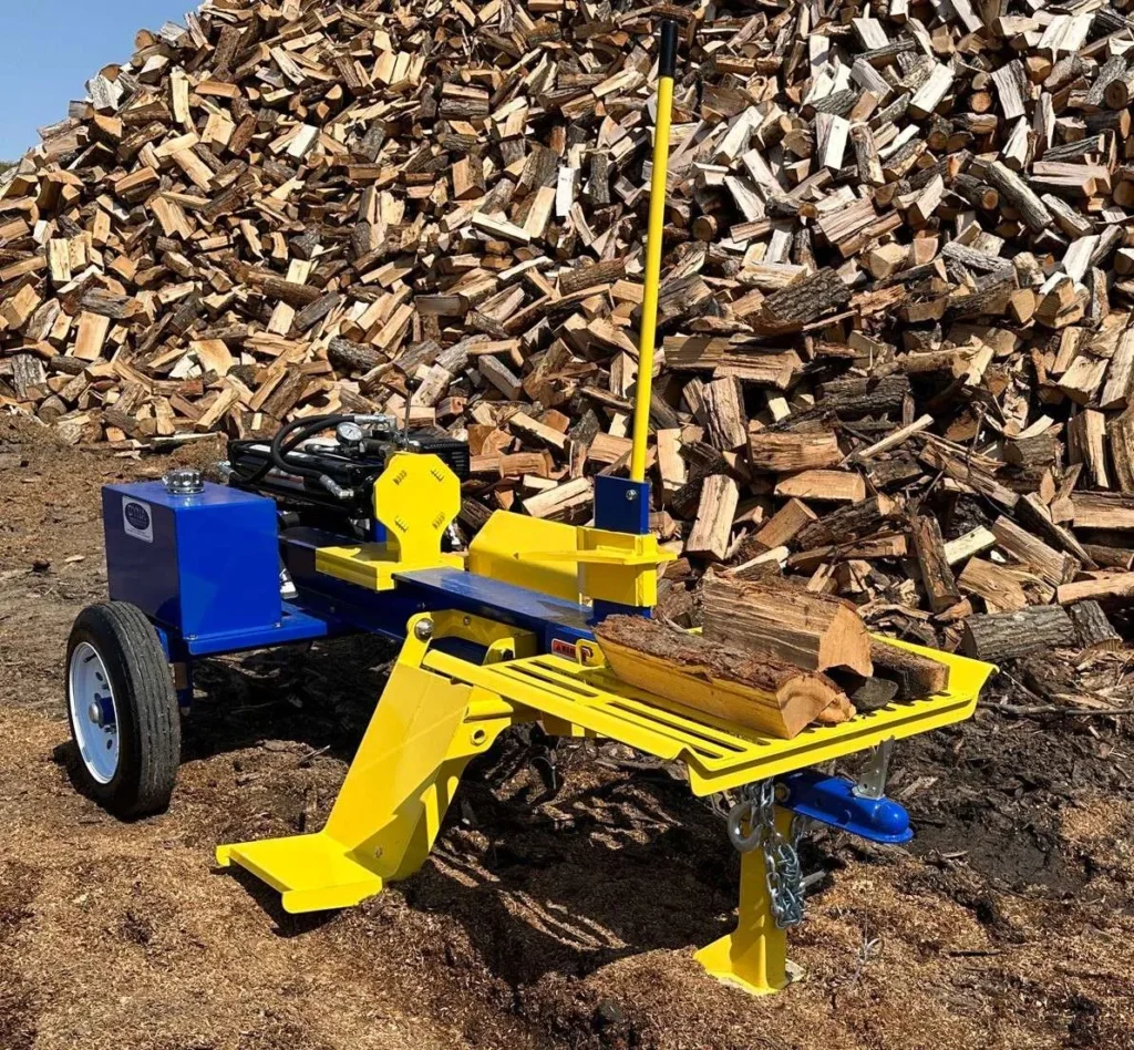
① Use the Oil Volume for Each Direction
Pump flow rate is the volume of oil delivered per unit of time. For a typical double-acting cylinder, assuming no leakage and no oil compression, the oil volume required in a given direction is approximately the effective area of the inlet chamber × the travel distance; the ideal motion time is approximately the oil volume ÷ the actual flow rate supplied to that chamber. The entire piston area is used for extension, while the annular area (after subtracting the rod cross-sectional area) is used for retraction. Therefore, for the same stroke and inlet flow rate, the oil consumption and motion time typically differ in the two directions.
Using the same hypothetical cylinder as before, with a full stroke of 500 mm: the theoretical oil requirement for extension is approximately 3.93 L, and for retraction, approximately 2.95 L. Assuming the oil supply flow rate in both directions is 40 L/min throughout the entire stroke, the full extension takes approximately 5.89 s, the full retraction approximately 4.42 s, and a round trip approximately 10.31 s. These are ideal motion times under constant flow conditions and do not account for directional changes, pauses, leakage, or the loading and unloading of lumber.
② Split a Two-Stage Pump Cycle into Its Actual Flow Phases
Many log splitters use two-stage pumps: they approach or retract quickly at a high flow rate when resistance is low; when the load causes the pressure to reach the switching threshold, the high-flow pump stage unloads—that is, it no longer supplies that portion of the flow to the working circuit—and the remaining pump stage maintains a higher working pressure at a lower flow rate. **The “low pressure, high flow” specification in the catalog does not represent the flow rate during the splitting process. ** The switching point depends on the load and the pump configuration; switching does not occur at the same point for every log.
For example, using the same hypothetical cylinder, assume that the first 400 mm of the approach stroke occurs at 40 L/min, the subsequent 100 mm of the splitting stroke occurs at 10 L/min, and the entire retraction stroke returns to 40 L/min:
| Assumed Phase | Stroke | Assumed Inlet Flow | Theoretical Movement Time |
|---|---|---|---|
| Rapid Approach | 400 mm | 40 L/min | 4.71 s |
| Splitting Under Load | 100 mm | 10 L/min | 4.71 s |
| Full Retraction | 500 mm | 40 L/min | 4.42 s |
| Theoretical Total Round Trip | 500 mm each for extension and retraction | Calculated in segments | 13.84 s |
This does not represent the actual cycle time of the log splitter; it merely illustrates why a single flow rate figure for the pump cannot be used to calculate the entire sequence of operations. If increasing the cylinder bore is being considered, first recalculate the no-load approach, loaded splitting, and retraction times separately using the actual flow rate of the original machine. If the rod diameter is also changed, recalculate the return flow cross-sectional area and check the return oil passages: during retraction, the oil volume discharged from the rodless chamber may exceed the oil volume entering the rod chamber.
Compare Replacement Cylinder Specifications and Purchasing Options
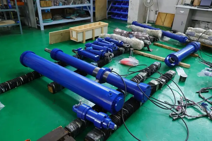
When an original manufacturer’s part number is available, you can first look up the original manufacturer’s replacement part that corresponds to the equipment model, serial number, and version. When comparing other candidates, list the installation type, bore and rod diameter, stroke, port configuration, operating mode, and allowable working pressure in a single specification comparison table. If the original cylinder is discontinued or its part number cannot be found, you should first verify the drawings and operating conditions; Candidate parts that are similar only in tonnage, stroke, or overall dimensions should still not be marked as direct replacements.
If you are familiarizing yourself with GY Hydraulic’s product categories, you can view the double-acting hydraulic cylinders page. This page can be used to understand category and specification fields; specifically for log splitters, it is recommended to separate publicly available information from the details that need to be confirmed for this procurement:
| Comparison Fields | Public Information on Official Website Category Page | Details to Confirm for This Procurement |
|---|---|---|
| Operating Mode | Double-acting; both extension and retraction are hydraulically driven | Whether it meets the original machine’s valve circuit and return stroke requirements |
| Dimensions and Mounting | Lists bore diameter, rod diameter, stroke, and mounting options such as lugs and flanges | Mounting reference points at both ends, pin diameter, mounting width, fully retracted and fully extended dimensions, and actual external dimensions |
| Port Connections | Includes connection options such as BSPP and metric | Thread type, dimensions, seal type, position, and orientation required by the original equipment |
| Operating Pressure | Category data is determined based on hydraulic system requirements | Rated operating pressure of candidate cylinders under these operating conditions and basis for compatibility |
| Procurement Terms | Category data cannot confirm specific available models for the log splitter | Written quotation, scope of supply, stock availability or lead time, shipping costs, and after-sales terms |
For example, if one quote includes both end fittings and mounting pins, while another includes only the cylinder assembly, the prices of the two quotes should not be directly compared. First, request clarification on the scope of components and the drawing version; only after confirming that the technical specifications are consistent should prices and delivery times be compared. Even if supply is readily available, verification of compatibility with the complete machine must not be omitted.
Prepare Cylinder Specifications for Fit Verification and a Quote
When requesting a quote, we recommend providing a set of matching documentation: equipment brand, model, and serial number; original cylinder part number and a photo of the nameplate; installation drawings or photos with dimensional annotations; verified cylinder bore diameter, rod diameter, stroke, mounting dimensions at both ends, and oil ports; operating mode, system operating pressure, and return stroke requirements; purchase quantity and delivery destination. If you need to change dimensions or increase cycle speed, also include the pump model, flow rates at each stage, and the original machine’s cycle time; clearly mark any unverified data as “to be confirmed.”
For example, if the original cylinder nameplate has been worn away, you can provide equipment drawings, photos of the mounting dimensions at both ends, and photos of the hydraulic ports, noting which dimensions come from the drawings and which are based on on-site measurements. When evaluating hydraulic cylinder solutions, you can submit your information via the GY Hydraulic contact page. First, confirm whether the candidate specifications match the original machine’s installation, output, and return stroke requirements; then provide a quote and place an order based on the confirmation results. Do not assume compatibility based on unsubstantiated assumptions such as “it looks like it will fit.”
Choosing a Trusted Hydraulic Cylinder Manufacturer
From standard hydraulic cylinders to custom solutions, we help you improve equipment performance, delivery reliability, and batch consistency
Explore Rivmate Cases

Hey There, I'm Melody!
We are a hydraulic cylinder manufacturer. For over 20 years, we have focused on producing reliable hydraulic cylinders. Need a hydraulic cylinder solution? Feel free to contact us.