Home / Hydraulic Ram vs. Cylinder: What’s the Difference?
Hydraulic Ram vs. Cylinder: What's the Difference?
- Author: GY Hydraulic
- 20+ Years of Manufacturing
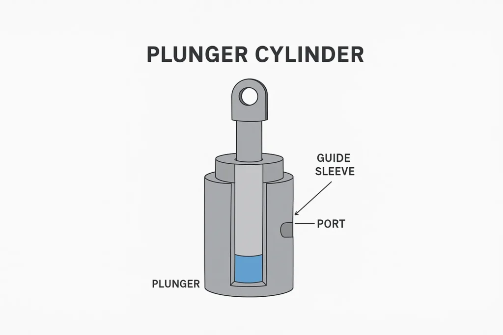
“Hydraulic ram” is sometimes a colloquial term for a hydraulic cylinder, and other times it specifically refers to a plunger-type hydraulic cylinder. If someone says, “The ram on this piece of equipment is leaking oil,” they may simply be referring to the entire cylinder; if the drawing specifies a plunger-type cylinder, it refers to a specific design: hydraulic pressure directly pushes a plunger that extends from the cylinder body, typically without a conventional piston that moves along the inner wall of the cylinder barrel and is equipped with seals.
To understand the difference between a hydraulic ram and a hydraulic cylinder, it is crucial to distinguish between the terminology, internal structure, and retraction mechanism. When working with used parts, you must verify which surface is pushed by hydraulic pressure, what mechanism causes retraction, and whether the installation and operating conditions of the new part are consistent with those of the used one. The terms “ram” or “cylinder” alone are insufficient to determine whether new and used parts are interchangeable.
Table of Contents
Does Hydraulic Ram Refer to Any Hydraulic Cylinder or a Plunger-Type Cylinder?
In lifting equipment catalogs or maintenance discussions, ram can refer to the entire hydraulic cylinder. However, when technical documentation discusses internal structure, ram-type cylinder may specifically refer to a plunger-type hydraulic cylinder. These two terms are not mutually exclusive: **plunger-type hydraulic cylinders are a type of hydraulic cylinder, but cylinders referred to as “rams” in the field are not necessarily plunger-type. ** Some parts documentation also refers to the extended piston rod as a ram; in such cases, you must clarify whether the term refers to the rod itself or the entire assembly.
| What you see or hear | What it might mean in this context | How to confirm |
|---|---|---|
| A maintenance technician says, “Replace this hydraulic ram” | The entire hydraulic cylinder; internal structure not specified | Look up the equipment part number, the old cylinder nameplate, or the assembly drawing |
| Drawing labeled plunger-type cylinder or explicitly states “plunger-type” | A structure where the plunger itself is pressurized and delivers linear force | Verify the sectional view, pressure-bearing surfaces, and seal locations |
| Purchase order simply states hydraulic cylinder | The general category of hydraulic cylinders | Specify internal structure, return mechanism, and operating conditions |
For example, if the procurement department receives a maintenance work order stating “replace lifting ram,” it is best to first clarify whether the entire cylinder needs to be replaced or just the worn-out extending component, and then identify the official designation on the drawings. Another easily confused term, hydraulic ram pump, refers to a water hammer pump—a device used to transport water—which is different from the push-pull actuators discussed in this article.
How to Distinguish Plunger-Type and Piston-Type Hydraulic Cylinders
① Look at the Moving Part and the Seal Location
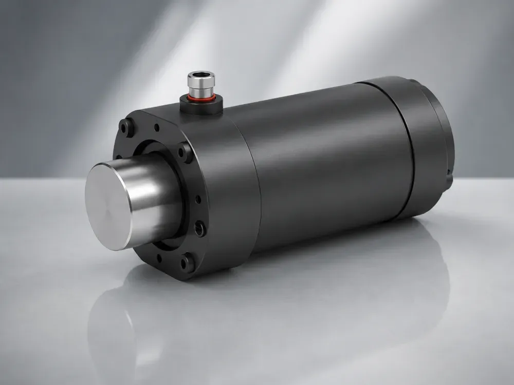
When examining a cross-sectional view, first identify which section is moving, then locate the seal that blocks the pressurized oil. A seal is a component that prevents fluid from leaking through gaps. In a typical straight-rod piston design, the piston itself is the cylindrical moving part that enters and exits the cylinder. When it extends, hydraulic pressure acts on the effective pressure surface of the plunger; the primary working seal is typically mounted in a fixed seal seat at the cylinder port, in contact with the outer circumference of the moving plunger. There may be guide or stop components inside, but there is not necessarily a conventional piston that seals while sliding along the inner wall of the cylinder barrel.
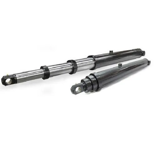
In a common single-rod piston cylinder, the piston is the component driven by hydraulic pressure inside the cylinder barrel, while the piston rod transmits its motion outward. The piston and rod may be an assembly or a single piece; the key to identification is whether the piston and the piston seal moving with it are visible. The piston seal prevents fluid from flowing from one side of the piston to the other; there is also a rod seal at the cylinder end to prevent fluid leakage along the extended rod. The following comparison focuses only on typical straight-rod plunger-type and standard single-rod piston-type designs; special configurations should be confirmed based on the original drawings.
| Identification Points | Typical Straight-Rod Plunger Type | Common Single-Rod Piston Type |
|---|---|---|
| Moving Parts | The plunger itself moves in and out of the cylinder body and transmits force | A piston inside the cylinder drives the piston rod in and out |
| Piston Structure | Typically does not have a conventional piston that seals by sliding against the inner wall of the cylinder | Includes a piston and piston seal; the piston is not necessarily a separate, removable component |
| Primary Motion Seal Location | Fixed cylinder port seal slides relative to the outer circumference of the plunger | Piston seal moves along the inner wall with the piston; cylinder port rod seal slides relative to the piston rod |
| Projecting Pressurized Area | For simple straight-rod plungers, typically calculated based on the effective plunger diameter | Oil is supplied from the side of the piston without a rod; calculated based on the total piston area |
For example, in the case of two used parts where only a single chrome-plated round rod is visible on the outside: one of them may be the plunger itself, while the other may simply be a rod connecting to an internal piston. The diameter of the exposed rod cannot be used as a substitute for the bore diameter. The bore diameter refers to the inner diameter of the cylinder barrel; when a cross-sectional diagram is unavailable, verify using the model number or parts catalog—do not judge the internal structure based on the thickness of the rod, the shape of the cylinder port, or the location of oil leaks.
② Compare Force Using the Correct Area
The theoretical force is calculated as pressure × effective cross-sectional area. For example, suppose one straight-rod piston has an effective diameter of 40 mm, and another piston cylinder also has a bore diameter of 40 mm; assuming the driving pressure in the respective extension directions is 8 MPa, and neglecting back pressure and friction, the theoretical extension force for both is approximately 10.05 kN. Back pressure is the pressure generated by resistance encountered when fluid is expelled; it partially offsets the output. The area here is approximately 1,256.6 mm²; 1 MPa (megapascal) = 1 N/mm², and 1 kN (kilonewton) = 1,000 N.
If the piston cylinder described above is double-acting—meaning both extension and retraction are driven by hydraulic pressure—and the rod diameter is 20 mm, the rod’s cross-sectional area must be subtracted from the total piston area during retraction. At the same pressure of 8 MPa, and assuming the back pressure in the other chamber and friction are negligible, the theoretical retraction force is approximately 7.54 kN. However, this value cannot be used to estimate the return force for a single-acting piston retracted by an external force. This example illustrates that the term “ram” does not necessarily imply greater thrust, nor does it indicate the stroke length; when purchasing, you should confirm the direction, actual pressure, and corresponding area.
How Ports and Return Methods Help Identify Single- and Double-Acting Cylinders
Check What Drives the Return Stroke
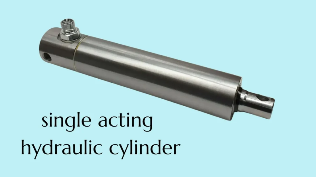
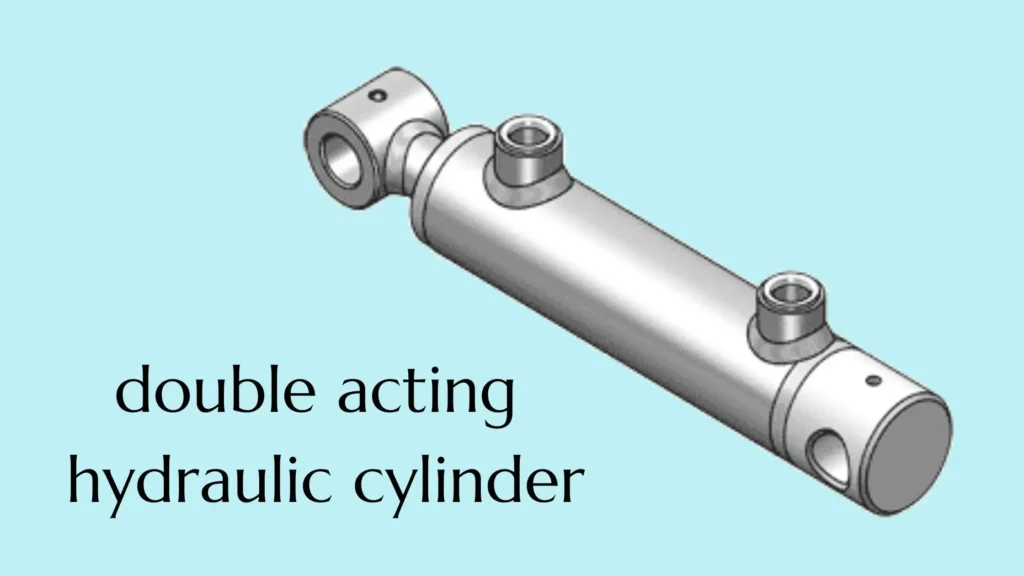
Single-acting and double-acting refer to the number of directions in which hydraulic pressure actively drives the cylinder. A single-acting cylinder is hydraulically driven in only one direction; a common configuration involves hydraulic extension, with retraction relying on gravity, an external mechanism, or a spring. A double-acting cylinder, on the other hand, directs pressurized oil to the appropriate side by reversing the flow, actively performing motion in both directions. Single-acting cylinders can be either plunger-type or piston-type; these two terms are not interchangeable.
| Return Mechanism | Common Operating Mode | Conditions to Verify |
|---|---|---|
| Gravity or External Load Return | Hydraulic pressure drives the working direction; Return stroke driven by self-weight, load, or an external mechanism; hydraulic fluid has a corresponding discharge path | Whether external forces can still overcome friction and return flow resistance under no-load conditions or in the most unfavorable position |
| Spring-Return | Hydraulic pressure drives the working direction; the spring returns the moving part to its original position within permissible limits | Whether the spring can overcome actual resistance throughout the entire return stroke; The reaction force of the spring must also be considered in the working direction |
| Hydraulic Active Retraction | Retraction is also driven by hydraulic pressure, with fluid on the opposite side discharged through the corresponding flow path | Are there sufficient pulling force, flow rate, and appropriate valve circuits in the retraction direction? |
For example, a piston cylinder used for vertical lifting can utilize the weight above it for retraction; however, when switched to horizontal material feeding, the same gravitational force may not necessarily allow the piston to return along the axis. If the equipment requires an active retraction mechanism, verify the double-acting configuration and retraction force; if only reset is required, verify whether a spring-return structure that meets the requirements is available. While there are indeed specially designed spring-return piston cylinders, this must be verified by specific model—do not assume that all piston cylinders come equipped with springs.
Identify the Function of Each Port
A visible oil port typically indicates a single-acting cylinder, but this is not conclusive evidence: in some cylinders, the oil lines are connected via the mounting bracket or internal passages, so not all working ports may be visible from the outside. Conversely, two visible ports do not necessarily drive extension and retraction separately; one of them could be a vent port, a pressure measurement port, or a spare port for the same oil chamber. The key question is which chamber each port is connected to and in which direction it is pressure-driven, rather than simply counting the external ports.
In practice, you can compare photos of both ends of an old cylinder and the valve block with the hydraulic schematic. The schematic uses symbols to indicate where fluid enters and exits under different control states; it provides a clearer indication of which component handles the return stroke than photos do. When information is incomplete, mark the port functions as “to be confirmed”; do not remove plugs or temporarily connect fluid to test operation. The return mechanism is not the same as the safety hold-position mechanism: for loads that may drop, separately verify load holding and maintenance supports according to equipment requirements.
What to Confirm Before Ordering a Replacement Hydraulic Cylinder
Collect the Information That Determines Fit and Function
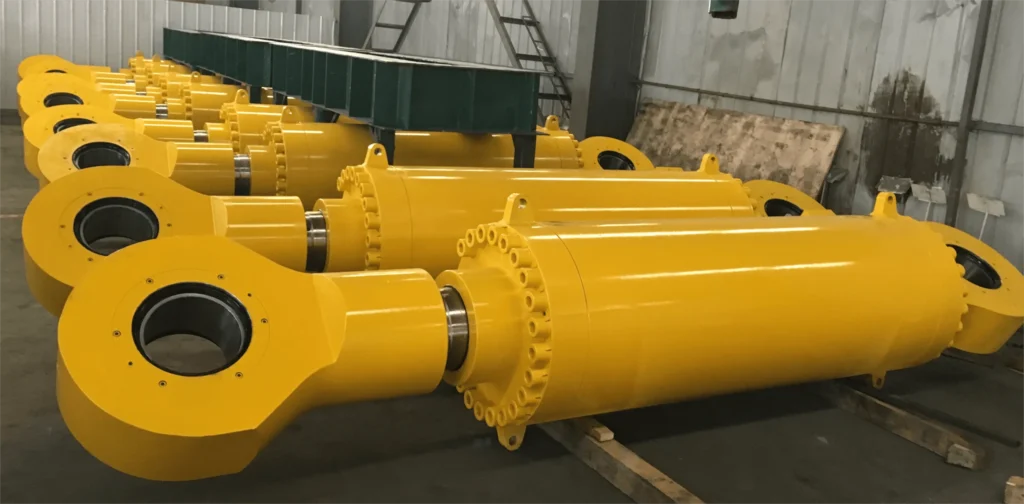
First, locate the original cylinder model, equipment part number, and installation drawing; then use photographs to supplement the details of the oil ports, ends, and surrounding space. Stroke refers to the distance traveled by the moving part, while the retracted installation length is the distance between the two mounting reference points when the device is fully retracted. When both ends are connected by pins, the measurement is typically recorded as the center-to-center distance between the two pin holes; for other configurations, measure according to the mounting surfaces specified in the drawing. Do not mistake the cylinder body length for the mounting center distance, nor the exposed rod length for the stroke.
- Identification and Structure: Original cylinder model or part number, equipment model, and drawing version; confirm whether to replace the entire assembly or individual parts, as well as whether it is a plunger-type or piston-type, and single-acting or double-acting.
- Stroke and Installation: Effective stroke, retracted and extended installation dimensions, available installation space; record pin hole diameter and connection width, as well as thread or flange dimensions, according to the actual interfaces.
- Port Connections: Function, position, and orientation of each port; thread and seal types; if equipped with quick-connect fittings or a valve block, include the model number and photos of the connections. Quick-connect fittings are interfaces designed to connect piping according to matching specifications; the fact that they can be connected does not prove that their functions are the same.
- Output and Operating Conditions: Working pressure and achievable pressures in both chambers; required thrust or pull force; direction of force; speed; return mechanism; mounting orientation; and operating environment; if there are shock or load-holding requirements, specify them separately.
- Applicable Internal Dimensions: For straight-rod piston types, prioritize confirming the effective piston diameter; for piston types, record the cylinder bore and rod diameter as shown on the drawings. If dimensions are unknown, write “To be confirmed”; do not substitute the external rod diameter for the cylinder bore.
Verify the Replacement Against the Actual Task
For example, among two cylinders rated for a 200 mm stroke, one may have a retraction length that is too long to fit into the original mounting location; or both may fit, but one may only be able to return to its home position by gravity, failing to meet the original equipment’s requirement for active retraction. If the load direction or retraction method changes, the valves, piping, and load-bearing arrangements after the cylinder stops must also be verified. Do not place an order based solely on the “ram” designation and then attempt to remedy the situation by modifying mounting holes or replacing fittings.
You can send clear photos of the nameplate, the connections at both ends and the hydraulic ports, installation drawings, and the parameters mentioned above to GY Hydraulic to discuss the design and interfaces of replacement hydraulic cylinders. On-site verification should be performed by qualified personnel in accordance with equipment requirements. Do not confirm specifications by disconnecting hoses or repeatedly testing the cylinder until it has been confirmed that the load is supported and residual pressure is controlled.
Choosing a Trusted Hydraulic Cylinder Manufacturer
From standard hydraulic cylinders to custom solutions, we help you improve equipment performance, delivery reliability, and batch consistency
Explore Rivmate Cases

Hey There, I'm Melody!
We are a hydraulic cylinder manufacturer. For over 20 years, we have focused on producing reliable hydraulic cylinders. Need a hydraulic cylinder solution? Feel free to contact us.