Home / 2 Stage vs 3 Stage Hydraulic Cylinders
2 Stage vs 3 Stage Hydraulic Cylinders
- Author: GY Hydraulic
- 20+ Years of Manufacturing
When selecting between two-stage and three-stage telescopic hydraulic cylinders, the key considerations are whether the available installation space, the required stroke and the working capacity of each stage are compatible. A three-stage configuration is generally worth considering when retraction length is a constraint; however, adding an extra stage does not necessarily result in greater lifting force, faster operation or a longer service life. If a two-stage configuration already meets the requirements for dimensions, force output, speed and stability, there is no need to opt for a three-stage design simply for the sake of having more stages.
This guide from GY Hydraulic, ‘2-Stage vs 3-Stage Hydraulic Cylinders’, discusses hydraulic cylinders that extend via nested multi-stage sleeves. You will learn how to compare installation dimensions, calculate force and speed at each stage, and why focusing solely on ‘total stroke’ and a single maximum lifting capacity may still lead to selecting the wrong product.
Table of Contents
Define Stage Count and Confirm the Manufacturer Convention
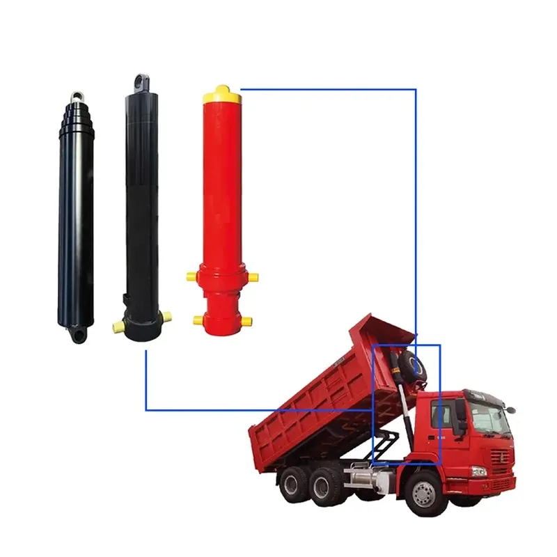
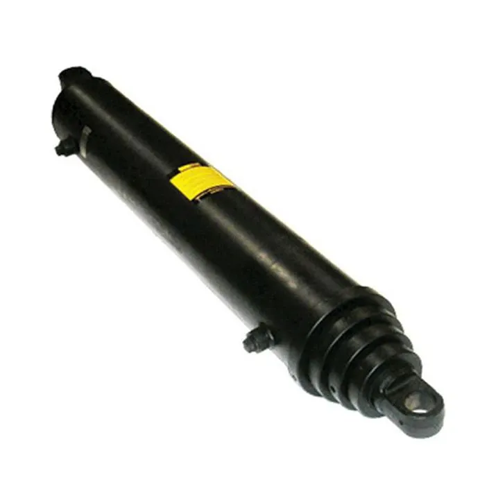
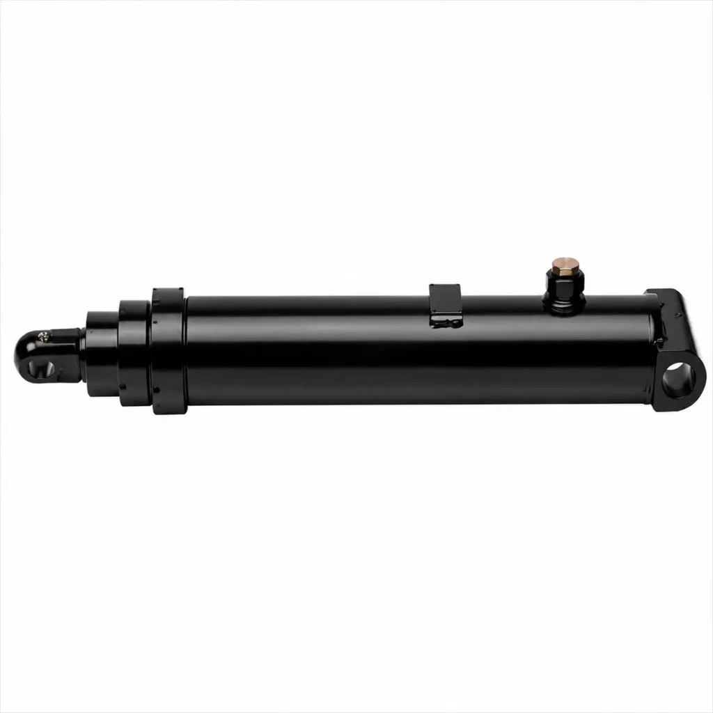
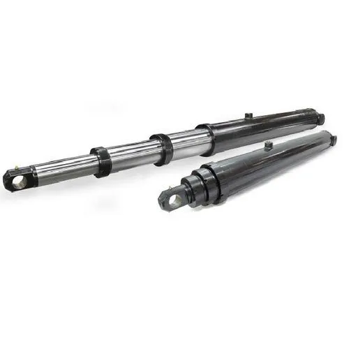
Telescopic hydraulic cylinders consist of sleeves of gradually decreasing diameter that nest inside one another; they stack together when retracted and extend relative to one another during operation. The term ‘stage’ commonly refers to the number of working stages that can extend relative to the outermost cylinder section; the outermost main cylinder is not usually counted. The innermost final stage may still constitute a working stage and must not be omitted simply because it does not resemble a hollow sleeve. In accordance with this definition, this article interprets ‘two stages’ as two extending stages and ‘three stages’ as three extending stages.
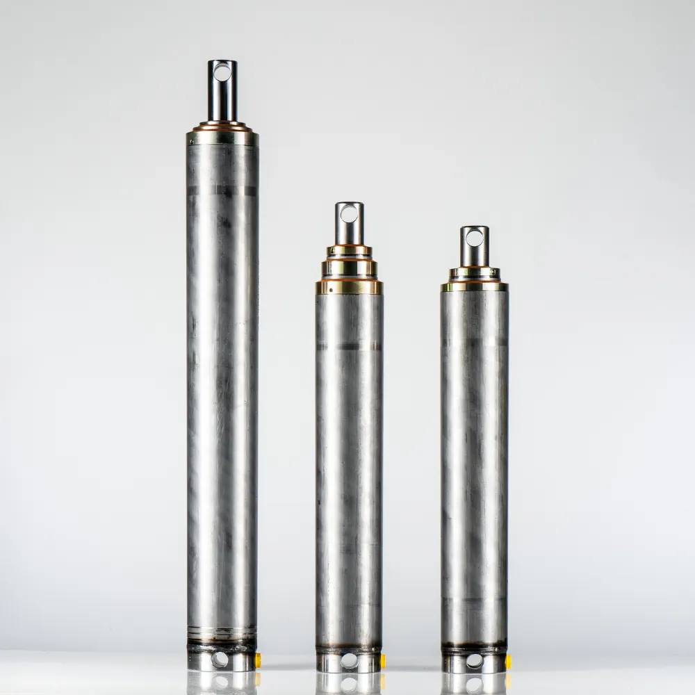
When actually procuring such components, it is still necessary to confirm how the manufacturer names and numbers them. For example, if you observe one main cylinder and two extending sections, you should not simply refer to it as a ‘three-stage cylinder’ merely because you can see three metal sections in total. You may request that the supplier mark the main cylinder, each extending stage, and the effective stroke of each stage relative to the outer component on a cross-sectional drawing. The effective stroke is the distance that a stage is permitted to travel according to the design, excluding the length that remains inside to provide support.
Similarly, do not confuse the number of stages referred to here with the number of pistons in a series-tandem structure. The former primarily achieves a longer stroke through nesting, whilst the latter aggregates output force through multiple mechanically linked pressure areas. Only after confirming the subject under discussion should you compare two-stage and three-stage designs, to avoid placing parameters from different structures in the same table.
Compare Extended Reach and Retracted Length
Use the Same Measurement References
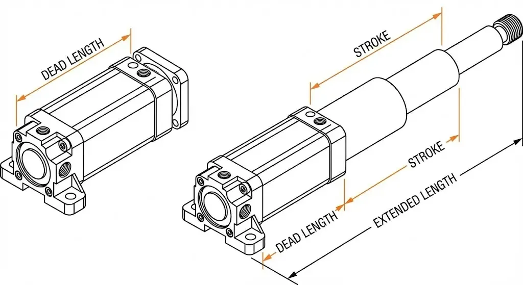
First compare the installation dimensions, then compare the ‘extendable length’. The retracted length is the length when fully retracted; the extended length is the length when fully extended; and the total stroke is the difference between the two. For cylinders mounted on pins at both ends, the distance between the centres of the two mounting pin holes is commonly used as the reference; for other mounting methods, measurements should be taken relative to the reference plane specified in the drawings. The overall external length of the cylinder body must not be confused with the mounting centre distance.
Provided the measurement reference is the same and the structure of the mounting ends remains unchanged, the following formula may be used: Extended mounting length = Retracted mounting length + Total stroke. The total stroke comprises the effective strokes of each stage when extended relative to the previous one; however, as the strokes of each stage are not necessarily of equal length, the total stroke must not be divided equally between two or three stages without prior confirmation from the drawings.
For example, if two cylinders are both specified as having a stroke of 1,500 mm, but one has a shorter retracted mounting length, its mounting length when fully extended will also be shorter. Therefore, ‘equal stroke’ does not mean that it will reach the same end position between the same set of mounting points.
Understand What an Extra Stage Can Change
Where other design conditions permit, a three-stage configuration can distribute the required stroke across more nested stages, thereby reducing the travel distance each stage needs to accommodate. However, the actual retracted length also includes space for end fittings, guides and seals, as well as the overlap length between stages. Guide components are responsible for supporting and guiding each stage along the axial direction; the overlap length is the portion that remains within the outer cylinder section after extension, serving to maintain these support conditions; it must not be arbitrarily reduced in pursuit of a shorter retracted installation length.
Below is a set of hypothetical candidate dimensions; these are not specifications for existing products, nor do they represent a fixed relationship between all two-stage and three-stage cylinders. Assume that the equipment requires a retracted installation length not exceeding 800 mm and a fully extended installation length of at least 2,200 mm.
| Hypothetical Scheme | Retracted Installation Length | Total Stroke | Fully Extended Installation Length | Preliminary Dimensional Assessment |
|---|---|---|---|---|
| Two-stage Scheme A | 900 mm | 1,500 mm | 2,400 mm | Extended length is sufficient, but will not fit when retracted |
| Three-stage Option B | 720 mm | 1,500 mm | 2,220 mm | Meets both dimensional criteria; other requirements still need to be checked |
This comparison illustrates that the three-stage option may resolve the retraction space issue, but the selection process should not be halted simply because it is shorter. You must also confirm that the final-stage output force, outer diameter, oil ports, hoses and mounting components all meet the requirements.
Check the Complete Motion Envelope
The motion envelope refers to the space occupied by a component throughout its entire range of motion. For lifting or tilting mechanisms, you need to check not only the two end positions, but also whether the cylinder swings during intermediate positions, whether the hydraulic port fittings and hoses come into contact with the frame, and whether there is any interference when fully extended.
For example, just because a three-stage cylinder can retract into the equipment does not mean there will necessarily be sufficient space for the fittings or follow-up hoses when it is extended. You should ask the supplier to provide an outline drawing showing the mounting ends and port locations, and then check each section in conjunction with the equipment’s motion diagram; do not simply compare the bare cylinder lengths listed in the catalogue.
Calculate Force at Each Stage Rather Than Using One Rating
Find the Effective Area for Each Working Stage
The effective area is the area over which hydraulic pressure is actually applied to generate axial force under a given operating condition; it is determined jointly by the position of the seals and the internal oil circuit. Seals are used to prevent fluid from leaking from one chamber to another or to the outside. The effective area of a telescopic cylinder cannot necessarily be calculated directly from the outer diameter of the cylinder barrel; in particular, for double-acting designs where both extension and retraction are hydraulically driven, as well as for special internal connection configurations, the area tables confirmed by the manufacturer should be used.
For common step-by-step extension designs, under the same cylinder chamber pressure, a smaller effective area generally implies a smaller theoretical thrust. A preliminary calculation can be made using F = p × A; if there is pressure on the opposite side, the counteracting force must be deducted, and losses such as friction must also be taken into account. When pressure p is expressed in MPa (megapascals) and area A in mm², the result is in N (newtons), as 1 MPa = 1 N/mm²; 1 kN (kilonewton) equals 1,000 N.
When the stages operate sequentially, the thrusts of the individual stages must not be added together and treated as the lifting force available throughout the entire stroke. Rather than requesting a ‘maximum lifting force’, a more practical requirement is to list the effective area, permissible pressure and available force at the corresponding positions for each stage in both the extended and retracted states.
Check a Three-Stage Example
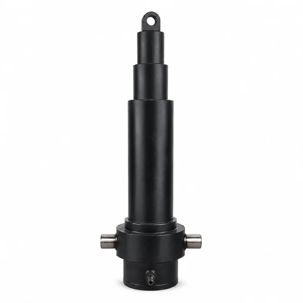
The following demonstrates the calculation using a set of hypothetical single-acting, sequentially extending structures; ‘single-acting’ refers to the fact that extension is driven solely by hydraulic pressure, whilst retraction relies on external force. Assume the manufacturer has confirmed that the effective diameters of the three extended stages are 100, 80 and 60 mm respectively, with an operating pressure of 16 MPa for each stage; friction and other losses are temporarily disregarded. The effective diameters given here are merely equivalent circular diameters used for calculating area; they must not be taken directly as the actual outer diameter of the stage cylinder or the inner diameter of the main cylinder.
| Operating Stage | Assumed Effective Diameter | Effective Area | Theoretical Extension Force at 16 MPa |
|---|---|---|---|
| First Stage | 100 mm | approx. 7,854 mm² | approx. 125.7 kN |
| Second Stage | 80 mm | approx. 5,027 mm² | approx. 80.4 kN |
| Third Stage | 60 mm | approx. 2,827 mm² | approx. 45.2 kN |
If a load acting directly along the cylinder axis requires 50 kN throughout the entire extension stroke, then these parameters are insufficient for the third stage, even if the first stage can theoretically generate a force far exceeding 50 kN. The theoretical pressure required for the final stage to overcome this load alone is approximately 17.7 MPa, which already exceeds the 16 MPa operating condition in this example, and this does not even account for losses.
The correct approach is to reassess the effective area, structure and pressure supply conditions, and to verify the permissible values for all components; one must not arbitrarily increase the system pressure simply to allow the final stage to continue moving. A two-stage configuration might be more suitable for this load if the final stage has a larger effective area; however, the assertion that ‘all two-stage cylinders are more powerful than three-stage cylinders’ is not universally true, and specific dimensions must still be compared.
Match Available Force to the Mechanism Position
The cylinder force required by the equipment does not necessarily remain constant throughout the entire stroke. For articulated lifting mechanisms, the load’s centre of gravity and the lever arm vary with angle; the lever arm is the perpendicular distance from the direction of the applied force to the pivot axis, and it influences the cylinder force required to generate the same rotational torque.
For example, certain tilting mechanisms require greater thrust at the start of the stroke; as the angle increases, the required cylinder force decreases, and a smaller final-stage cylinder may still be sufficient. However, this must be verified by actual geometric and load calculations; it cannot be assumed simply because ‘the latter half of the stroke should be effortless’. You should request that the switching positions for each stage, the available force and the force required by the mechanism be presented on the same position table or graph, so that you can check whether they match at each stage, rather than merely comparing the maximum values at the start of the stroke.
Compare Stage Speed and Hydraulic Flow Demand
Expect Speed Changes When Effective Area Changes
Flow rate is the volume of oil flowing into or out of the oil chamber per unit of time. For the hypothetical structure described above—where relative extension is primarily achieved by a single stage and the relationship between the effective area and stroke has been established—the speed can be estimated using v = Q ÷ A, provided that leakage and oil compression are neglected. Given that the actual flow rate into the cylinder remains constant, the smaller the effective area, the higher the speed.
Using the areas from earlier, and assuming a constant oil supply flow rate of 20 L/min, we obtain:
| Working Stage | Theoretical Extension Speed | Theoretical Time for Uniform Extension if the Stage Stroke is 400 mm |
|---|---|---|
| First stage | Approx. 42.4 mm/s | Approx. 9.42 s |
| Second stage | Approx. 66.3 mm/s | Approx. 6.03 s |
| Third stage | Approx. 117.9 mm/s | Approx. 3.39 s |
This explains why, in some telescopic cylinders, the output end accelerates noticeably upon entering a smaller stage. A three-stage system involves one additional stage transition compared to a two-stage system; however, whether the change in speed is greater depends on the ratio of cross-sectional areas between stages and the flow control, and cannot be determined by the number of stages alone. Furthermore, the speeds shown in the table do not imply that the load on the equipment will move at the same linear velocity, as the link mechanism will also alter the displacement relationship.
Calculate Total Oil Volume and Cycle Time
Under the sequential motion conditions of this example, the oil inflow required for each stage can be calculated using the formula Vᵢ = Aᵢ × sᵢ, where sᵢ is the relative stroke of that stage. Summing the oil volumes for each stage yields the theoretical oil inflow for this extension stroke; one must not simply multiply the area of the largest stage by the total stroke, nor assume that a ‘three-stage’ system necessarily consumes more oil than a two-stage one.
If each of the three stages extends by 400 mm, with a total stroke of 1,200 mm, the total theoretical oil volume is approximately 6.28 L. At a constant flow rate of 20 L/min, the theoretical extension time is approximately 18.85 s. In practice, one must also factor in start-up, stage-changeover, deceleration and dwell times; furthermore, if the pump’s oil delivery varies with pressure, one cannot continue to calculate the entire duration based on a fixed flow rate.
Size the Flow Control for the Whole Stroke
If you wish each stage to move at 50 mm/s, the assumed areas for this set require approximately 23.6, 15.1 and 8.5 L/min respectively. This implies that, to maintain an approximately constant speed, the oil supply must vary with the working stage, rather than selecting a single fixed flow rate. Whether to adopt staged flow control or position feedback should be determined based on permissible speed fluctuations, the equipment’s control capabilities and the actual circuit.
For double-acting telescopic cylinders, the effective retraction area and return flow rate must also be verified separately. In some designs, the retraction area varies between stages, whilst others utilise specific internal passages to achieve different flow relationships; therefore, the extension area table cannot simply be inverted for use. When the inlet and outlet areas differ, the return flow rate may exceed the pump’s supply flow rate; consequently, both directions must be checked when selecting valves, fittings and pipework.
Assess Stability, Side Loading, and Mounting Geometry
A two-stage design does not automatically imply stability, nor does a three-stage design automatically imply instability. Stability must be assessed in conjunction with the total extended length, the diameters and wall thicknesses of each stage, the lap length, the guide clearance, the mounting method and the actual loads. Buckling is a phenomenon whereby a slender, pressure-bearing component buckles laterally; Multi-stage telescopic cylinders consist of consecutive sections of varying diameters; it is not sufficient to simply substitute the diameter of the final stage into the simplified formula for a single rod to consider the verification complete.
Lateral loads are forces that deviate from the cylinder’s axis and cause the stage cylinders to undergo transverse bending. Alignment, on the other hand, ensures that the installation and direction of movement maintain an appropriate axial relationship. For example, non-parallel pins in a tilting mechanism, deformation of the mounting bracket, or the output end being pulled out of alignment by an external guide rail may all cause the cylinder stage to jam or suffer uneven wear. You should check the freedom of movement and guidance methods across the entire operating range; the telescopic cylinder must not be treated as a guide rail ensuring the lateral stability of the support frame.
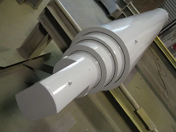
Increasing the overlap may improve support conditions, but it will also reduce the internal length, affecting the retracted dimensions. Therefore, if a three-stage solution is only just fitted due to a very tight overlap and minimal dimensional allowance, it requires thorough engineering verification rather than simply being approved on the basis that ‘it fits’. For tipper equipment, the vehicle’s support, ground conditions and load offset must also be assessed separately; the fact that the cylinder itself meets load-bearing requirements does not guarantee that the entire vehicle will not become unstable during the lifting process.
Compare Single-Acting and Double-Acting Options
The number of stages and the operating mode are two independent options. Single-acting cylinders are typically extended by hydraulic pressure, whilst retraction relies on the load, gravity or other external forces; double-acting cylinders, on the other hand, utilise hydraulic pressure for both extension and retraction. Consequently, both two-stage and three-stage configurations may employ different operating modes depending on the application; ‘three-stage’ should not be interpreted as ‘double-acting’.
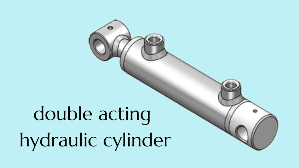
For example, in a lifting mechanism that relies on the weight of the carriage to retract, a single-acting solution may be evaluated; however, it is necessary to confirm whether the return force can overcome seal friction and return flow resistance under no-load conditions, at low temperatures, and at unfavourable angles. Mechanisms involving horizontal thrust or requiring active retraction typically require a double-acting solution to be assessed, as gravity may not assist retraction along the cylinder axis.
However, the descent speed of a single-acting mechanism can also be adjusted through appropriate return flow control and is not entirely uncontrollable; nor does double-acting necessarily imply automatic locking upon pressure loss. You should simultaneously specify requirements for retraction force, retraction time, load holding and permissible movement following failure. If there are oil supply ports on the moving stage, you must also confirm the space available for hose bending, protection and retraction/extension throughout the full stroke; it is not sufficient to merely check whether the cylinder body fits.
Weigh Sealing Complexity, Maintenance, and Total Cost
Under similar design and manufacturing conditions, an additional working stage typically entails more inter-stage seals, guides and surfaces subject to relative motion, and may also increase the number of points requiring inspection and maintenance. However, one cannot therefore generalise that three-stage cylinders are more prone to oil leakage, nor can one guarantee that two-stage cylinders will have a longer service life. Sealing materials, surface quality, contamination, off-centre loading and operating cycles may all alter the outcome.
For example, when the final stage is exposed to sand, dust and wash water over the long term, the dust-proofing structure and surface protection may have a greater impact on maintenance performance than the designation of ‘two-stage’ or ‘three-stage’. Dust seals are components that scrape away external contaminants and moisture as the piston retracts; you should inspect the relevant protective features at each stage and record any scratches, corrosion or abrasion marks on the same side, rather than simply waiting for obvious oil leaks to occur.
When comparing total costs, include procurement, installation and modification, pump and valve adaptation, maintenance labour, spare parts and downtime losses on a single list. For instance, a two-stage solution may have one fewer maintenance access point but require relocation of the frame mounting points; a three-stage solution may avoid frame modifications but necessitate adjustments to flow control. You should request that suppliers provide information on the availability of seal kits, stage casings and guide components, as well as estimated maintenance turnaround times, and then compare these against the actual proposals; do not simply estimate prices based on the number of stages.
Choose Two or Three Stages from the Application Envelope
Set the Non-Negotiable Limits First
The scope of application here refers to the permissible combination of space, load, speed and environmental conditions for the equipment. First, clearly specify the conditions that cannot be altered: retracted and extended installation dimensions, permissible outer diameter, required thrust and pull forces at each position, system operating pressure, flow rate and target cycle time. The load specifications must also include direction, off-centre loading and holding time; it is not sufficient to state merely the weight of the object being lifted.
For example, “retraction not exceeding 800 mm, stroke of at least 1,500 mm” is still incomplete; you must also specify the end-point mounting distances, permissible speed variations, and the force required during the final stage of operation. Application tables provided by suppliers for telescopic cylinders typically list stroke, open and closed lengths, operating pressure, lateral or eccentric loads, and mounting orientation separately, indicating that these conditions must be confirmed collectively.
Compare Qualified Designs, Not Stage Labels
| Your actual circumstances | Evaluation criteria for two-stage solutions | Evaluation criteria for three-stage solutions |
|---|---|---|
| The two-stage solution already meets all installation and performance requirements | May be considered as a preferred option with fewer stages | The specific benefits of adding a further stage must be clarified |
| The two-stage solution has an excessively long retraction stroke, and the mounting point cannot be altered | Confirm whether other dimensional designs can meet the requirements | Focus on checking the final-stage force and support conditions for the short-retraction solution |
| Significant thrust still required in the latter section | Verify the area and permissible pressure of the final stage | Ensure that the addition of a smaller final stage does not become a performance bottleneck |
| Strict requirements for velocity stability throughout the entire run | Verify stage transitions and flow control | Design control is also required; adding an extra stage does not automatically ensure constant velocity |
| Dust, off-centre loading or poor maintenance conditions | Verify protection, guidance and spare parts | In addition to the above items, assess the maintenance requirements for the new stages |
If both schemes meet the mandatory requirements, then compare weight, modification workload, control complexity and total cost. Do not decide in advance that ‘a three-stage design is superior’, nor accept a two-stage cylinder that cannot be fitted or has insufficient stroke simply to reduce the number of stages.
Confirm the Stage Transitions Before Approval
Prior to placing an order, the supplier should be asked to confirm the stroke and effective area of each stage, the permissible pressure, the expected retraction and extension sequence, the load-bearing capacity and stability in critical extended positions, as well as dimensional drawings corresponding to the mounting ends. The equipment owner should also verify the changes in motion during stage transitions and agree on appropriate acceptance criteria; merely passing a pressure test does not prove that the lifting force, speed and overall stability of the entire system are satisfactory.
When submitting requirements to GY Hydraulic, please include equipment motion diagrams, original cylinder part numbers or drawings, installation centre distances, load variations with position, and parameters of existing pumps and valves. Ultimately, a solution capable of completing the entire motion cycle within the actual application range should be selected, rather than placing an order based solely on the designation of ‘two-stage’ or ‘three-stage’.
FAQs
Does adding a stage always increase total lifting force?
No. In common telescopic cylinders, different working stages are used sequentially, and the forces at each stage cannot simply be added together; when a smaller final stage is added, its effective area may even become the limiting factor for the force output in the latter half of the stroke. For example, in the previous section, the theoretical force of the final stage in a three-stage configuration was assumed to be only 45.2 kN; the 125.7 kN of the first stage cannot be used to represent the full stroke. You should check the available force at the corresponding position for each stage, rather than multiplying a single lifting value by the number of stages.
Can a two-stage cylinder replace a three-stage cylinder directly?
It cannot be replaced directly simply because the total stroke is the same. It is necessary to verify the retracted and extended installation dimensions, mounting fittings, outer diameter, force-velocity relationships for each stage, oil volume, mode of action and sequence of operation. For example, a two-stage cylinder may have sufficient stroke but be unable to return to its original installation position due to a longer retraction length. Before replacement, the equipment owner and supplier should jointly verify the drawings and performance specifications; do not remove the old cylinder first and then attempt to adapt the bore on site.
Do telescopic stages always extend in the same order?
Not all designs are the same. Common sequential extension configurations typically progress from the larger working stage to the smaller one, but special hydraulic circuits or synchronised extension designs may employ different arrangements; the retraction sequence must also be confirmed for the specific model. If a cylinder originally specified to operate sequentially suddenly skips stages, becomes stuck or moves erratically simultaneously, operations should be halted to inspect the load, contamination, seals and oil supply conditions. Abnormal behaviour must not be mistaken for normal design, nor should operation be forced by increasing pressure.
Are three-stage cylinders always double acting?
No. ‘Three-stage’ refers to the number of extension stages, whilst ‘double-acting’ describes whether both extension and retraction are hydraulically driven; one cannot be inferred from the other. For example, a three-stage tipper lift cylinder may be single-acting, whilst a three-stage mechanism requiring active retraction may utilise a double-acting configuration or other specially designed combinations. You should examine the hydraulic circuit and return requirements; do not make judgements based solely on the number of stages or external connections.
Can a telescopic cylinder operate horizontally?
There are designs suitable for horizontal operation, but a cylinder originally selected for vertical lifting must not be used in a horizontal orientation without modification. Horizontal operation requires consideration of deflection caused by the weight of the extended stage, as well as guidance, support and reliable retraction. For example, in a horizontal material-pushing mechanism, one cannot rely on gravity to push a single-acting cylinder back along its axis. You should clearly specify the horizontal orientation, load direction and fully extended state to the supplier, who will then confirm the load-bearing and retraction solutions.
Does stage count alone determine service life?
No. Service life is determined by a combination of factors, including variations in operating pressure, cycle count, hydraulic fluid cleanliness, the condition of seals and surfaces, installation alignment and off-centre loading. For example, a two-stage cylinder that has been subjected to long-term off-centre loading and whose stage cylinders have been repeatedly scratched by sand particles cannot be guaranteed to last longer than a properly used three-stage cylinder simply because it has one fewer stage. You should compare design and maintenance requirements under similar operating conditions and should not accept service life figures expressed solely in terms of the number of stages.
Can damaged stages be repaired individually?
Some can be repaired or replaced individually, but the fit between that stage and the adjacent stage must first be checked. Damage may affect external sealing surfaces, internal guide surfaces, straightness or structural connections; it is not sufficient to simply address visible scratches. For example, before replacing a bent stage cylinder, the adjacent guide components and the cause of the lateral stress should also be examined. You may request the disassembly inspection report, the scope of permitted repairs, the fit dimensions and the test results following repair before deciding whether to carry out a localised repair or replace the entire assembly.
Is a three-stage cylinder the same as a three-position cylinder?
No. ‘Three-stage’ refers to the number of telescoping working stages, whilst ‘three-position’ describes the three output positions achievable by design. A three-stage telescopic cylinder does not automatically provide three repeatable, maintainable positioning points simply because it has three working stages. For example, if equipment requires three distinct positions—retracted, intermediate and extended—the positioning mechanism, detection and control requirements must be confirmed separately; the transition points between stages cannot be used as substitutes for the required positions.
Choosing a Trusted Hydraulic Cylinder Manufacturer
From standard hydraulic cylinders to custom solutions, we help you improve equipment performance, delivery reliability, and batch consistency
Explore Rivmate Cases

Hey There, I'm Melody!
We are a hydraulic cylinder manufacturer. For over 20 years, we have focused on producing reliable hydraulic cylinders. Need a hydraulic cylinder solution? Feel free to contact us.