Home / What Is a Tandem Hydraulic Cylinder? Design and Applications
What Is a Tandem Hydraulic Cylinder? Design and Applications
- Author: GY Hydraulic
- 20+ Years of Manufacturing
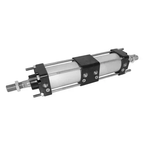
Tandem hydraulic cylinders combine two or more pistons arranged along the same axis into a single moving assembly via a shared piston rod or rigid connecting member, allowing the forces generated by multiple pressurised areas to be concentrated at a single output end. They are suitable for applications where lateral installation space is limited and the cylinder bore cannot be easily increased, but where there is still sufficient length along the direction of movement.
The term ‘tandem’ here primarily describes the mechanical arrangement; it does not imply that simply connecting the outlet of the front cylinder to the inlet of the rear cylinder will automatically increase the force at the same output end. When assessing this configuration, one must consider both the mechanical connection and the hydraulic circuit. This GY Hydraulic guide will address these two aspects to explain how it amplifies force, why the thrust does not necessarily double, and what trade-offs in terms of space and flow rate must be considered during selection.
Table of Contents
What Defines a Tandem Hydraulic Cylinder?
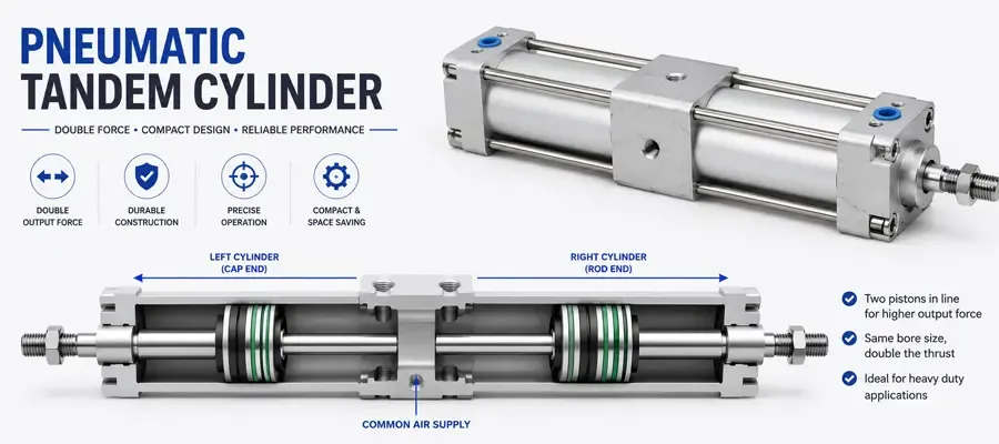
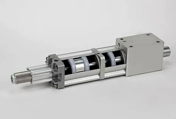
To determine whether a cylinder has a series-boosting configuration, three key factors must be considered: multiple pistons, mechanical linkage and combined output. The piston is the component within the cylinder that receives hydraulic pressure and moves; the piston rod transmits the force and motion to the external load. In a typical configuration, multiple pistons are arranged along the same axis and move together via a common piston rod or rigid connecting member, combining the forces generated by each piston at a single output end.
The mechanical connection determines how they move together, whilst the fluid supply method determines which pistons contribute to the force amplification. The chambers contributing to the output must be pressurised to the appropriate level, whilst allowing fluid on the opposite side to be discharged as designed, in order to generate the intended combined force. Therefore, the mere fact that two cylinders are arranged one behind the other, or connected by a hose, does not directly prove that they form a series-boosted configuration.

For example, if a press-fitting machine cannot accommodate thicker cylinders but still has space at the rear to install a longer assembly, it is worth evaluating this option. When you receive product documentation, you may first ask the supplier to mark the pistons, connecting rods and final output end on a cross-sectional diagram, before confirming which chambers are simultaneously supplied with fluid during force amplification. Do not rely solely on the term ‘tandem’ to make a judgement, as it may also be used for different designs, such as pneumatic-hydraulic combinations; the specific functionality still depends on the structure and fluid circuit.
How Multiple Pistons Combine Force on a Common Output
Add Forces Through the Mechanical Connection
Hydraulic pressure acts on the effective area of the piston, generating an axial force. The effective area is the area over which the pressure in that chamber is actually used to produce a force in the direction of motion; if a rod passes through this area, the cross-sectional area occupied by the rod must be deducted. When multiple pistons are subjected to a net fluid pressure in the same direction and are rigidly connected by a rod, these forces can be combined at a common output end.
You can think of this as two power units jointly pushing a single rod, rather than the first piston first ‘doubling’ the pressure before passing it on to the second. The force amplification stems from the increased effective area involved in the work, and does not require the supply pressure to increase proportionally with the number of pistons. Consequently, the rod end, mounting components and equipment frame must also withstand the increased resultant force; it is not sufficient to simply verify the pressure rating of each individual cylinder section.
Check the Rod Area Before Assuming Double Force
Two pistons of the same bore diameter do not necessarily equal twice the thrust of a single cylinder. The bore diameter refers to the internal diameter of the cylinder barrel, which is the pressure-bearing tube housing the piston and hydraulic fluid. If a connecting rod passes through the centre partition from the rear piston to the front piston, part of the front piston’s pressure-bearing surface may be occupied by the rod, leaving only an annular area to contribute to the force.
For example, if the benchmark is a standard single-rod cylinder with a rod protruding from only one end—which utilises the full piston area when extended—whilst the additional piston in the series configuration has only an annular area in the same direction, the additional force will be less than that of the first piston. Only when the effective area, actual pressure and loading conditions of each stage in that direction satisfy the corresponding relationships can we discuss a force approaching twice the original or any other specific multiple. One must not simply count the number of pistons whilst ignoring the rod in the cross-sectional diagram.
Keep Movement and Force Separate
Mechanical connections cause the pistons to move together; they do not automatically add their displacements. Stroke refers to the distance travelled by the output rod from the retracted to the extended position. When two pistons collectively complete a 200 mm movement, the output end typically moves 200 mm as a whole, rather than one moving 200 mm first and the other then moving a further 200 mm.
You should therefore confirm separately with the supplier both the combined output stroke and the oil supply status of each working chamber within that stroke. For example, if oil is supplied to only one power stage, the other stage will still be driven by the common rod; whether it can follow smoothly depends on whether the corresponding oil chamber has suitable inlet and outlet paths. Mechanical linkage does not mean that ports not currently in use can be blocked at will.
Identify Pistons, Rods, Chambers, and Hydraulic Connections
When examining a cross-sectional diagram, first trace back along the output rod to locate all the pistons, confirm which rod sections are integral and which are secured by connecting components, and then identify the partition plate that separates the cylinder sections. The cylinder chamber is the space on either side of the piston that contains the hydraulic fluid. The partition may serve both to guide the rod’s movement and to separate adjacent oil chambers via seals; seals are components that prevent fluid from leaking from one space to another or to the outside, so one must not limit the inspection to the outermost rod seals alone.
Next, label the oil ports and their functions for each chamber: which is the inlet and which is the outlet during extension, and how the configuration switches during retraction. Port connections may lead separately to the outside, or they may be combined via internal passages or an external manifold; therefore, the presence of only two external connections does not necessarily prove that there are only two working chambers internally. The Hydraulic Cylinders Inc. catalogue also distinguishes between ‘tandem’ configurations, where the rods are connected, and ‘multi-position’ configurations, where the rods are not connected.
A practical method of verification is to ask the supplier to use the same chamber numbering on both the sectional drawing and the hydraulic schematic. For example, number the ‘rear-stage extension chamber’ and the ‘front-stage extension chamber’ separately, and then specify whether they share a common oil supply and where the return flow goes on the opposite side. Only then can you determine the actual pressurised area, the venting location and the maintenance isolation boundaries, and avoid mistakenly assuming that two adjacent internal spaces are naturally interconnected.
Calculate Effective Area, Force, and Flow Requirements
① Calculate Every Active Area Before Adding Forces
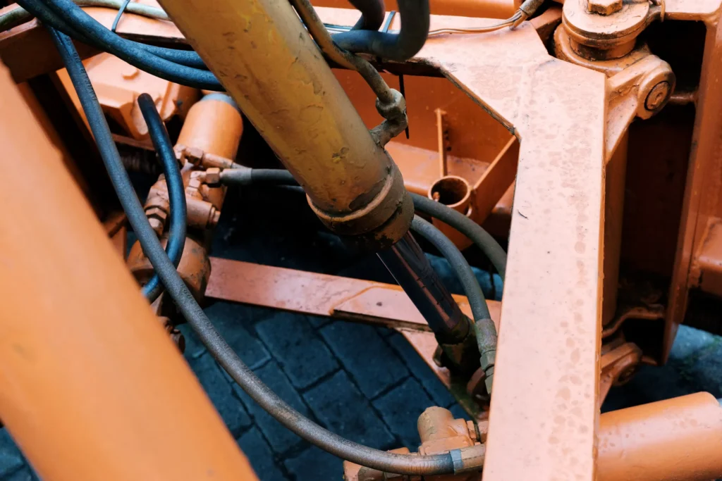
First, select the direction of force output, then calculate for each chamber whether the pressure acts as a driving force or a resistive force in that direction. For a circular piston and a concentric rod, the following formulae may be used:
- Total piston area: A = πD² ÷ 4.
- Annular area with the rod passing through that face: A = π(D² − d²) ÷ 4.
- Total net output force: F ≈ Σ (pressure in the assisting chamber × corresponding effective area) − Σ (pressure in the resisting chamber × corresponding effective area) − total frictional resistance.
Here, D is the cylinder bore diameter, d is the rod diameter passing through the corresponding pressurised surface, and Σ denotes the sum of the relevant terms. When pressure is expressed in MPa (megapascals) and area in mm², the product is N (newtons), as 1 MPa = 1 N/mm²; 1 kN (kilonewton) = 1,000 N. Only when the pressures in all assist chambers are identical may the areas be added together first and then multiplied by the same pressure.
Return line back pressure is the pressure generated as the oil flows through valves and pipework; it counteracts part of the output force. Pressure losses also occur in the supply lines; therefore, actual calculations should use the pressures in each cylinder chamber, rather than assuming that all port pressures are equal to the pump outlet reading.
② Work Through a Defined Two-Piston Example
The following is a hypothetical configuration intended to illustrate the principle; it does not represent GY Hydraulic product specifications or test results. Assume that the bore diameter of both cylinder sections is 80 mm, and that the connecting rod and the extending output rod both have a diameter of 40 mm. The rear end of the rear piston has no rod, whilst the connecting rod at its front end connects to the front piston; the front piston has a connecting rod on one side and an output rod on the other. The two pistons are rigidly linked; during extension, both assist chambers receive 16 MPa, whilst pressure on the opposite side and friction are temporarily disregarded.
| Power Stage | Effective Area During Extension | Effective Area During Retraction |
|---|---|---|
| Rear Piston | Full area, approx. 5,027 mm² | Area excluding connecting rod, approx. 3,770 mm² |
| Front-stage piston | Area minus connecting rod area, approx. 3,770 mm² | Area minus output rod area, approx. 3,770 mm² |
| Total | Approx. 8,796 mm² | Approx. 7,540 mm² |
The areas in the table have been rounded; the totals and subsequent calculations use the unrounded values. This yields a theoretical extension force of approximately 140.7 kN. For a standard single-rod cylinder with the same 80 mm bore diameter, applying 16 MPa across the full piston area results in a theoretical extension force of approximately 80.4 kN. Consequently, the extension force of this hypothetical structure is 1.75 times that of the reference benchmark, not twice as much.
If both retraction assist chambers were also pressurised to 16 MPa, and pressure and friction on the opposite side were ignored, the theoretical retraction force would be approximately 120.6 kN. Now consider the effect of back pressure: during extension, if both resistance chambers are at 2 MPa, the theoretical net hydraulic pressure would drop from 140.7 kN to approximately 125.7 kN, after which friction must also be deducted. This difference illustrates that determining whether a load is met cannot be based solely on the supply pressure multiplied by the total assist area.
③ Match Flow and Power to the Required Speed
Flow rate is the volume of oil entering or leaving the chamber per unit of time. For the arrangement described above, where the two pistons move at the same speed, each assist chamber is supplied directly with oil, and the return flow is channelled separately back to the reservoir, and provided leakage and oil compression are neglected: the total required supply flow rate Q = velocity v × the sum of the effective areas of the respective inlet chambers. Compatible units must still be used when calculating the flow rate; This relationship should not be directly applied to special circuits featuring fluid recycling pathways.
Continuing with the example above, if the total flow rate allocated to the two extension assist chambers is 30 L/min, the output speed is approximately 56.8 mm/s, and a uniform extension of 200 mm takes approximately 3.52 s, the combined oil inflow to both chambers is approximately 1.76 L. These figures do not include start-up, deceleration and dwell times.
If an extension speed of 100 mm/s is desired, the total oil supply flow rate would need to be approximately 52.8 L/min. Under ideal conditions where both assist chambers operate at 16 MPa, the corresponding hydraulic input power would be approximately 14.1 kW; the actual power required to drive the pump must also take losses into account. From this, you can conclude that a series configuration can increase force within the constraints of the cylinder bore, but does not increase power for free; when the pump flow rate remains constant, a larger total supply area generally implies a lower speed.
Furthermore, the return flow rate must be calculated separately based on the shrinking chamber area. Particularly during retraction, the volume of oil discharged may exceed the volume entering the other side; therefore, return valves and pipework must not be selected based solely on the pump’s supply flow rate.
Compare Tandem, Telescopic, and Series-Connected Cylinders

Separate Mechanical Layout from Hydraulic Connection
All three of these terms may lead beginners to think of ‘multi-stage cylinders’, but they address different issues. It becomes clear when you first consider how the output end moves, and then how the hydraulic fluid flows.
| Type | Main structural or connection features | Main problem addressed | Capabilities that cannot be directly inferred |
|---|---|---|---|
| Tandem hydraulic cylinder | Multiple pistons mechanically linked, acting on a common output end | Increases the available resultant force when lateral dimensions are limited | Doubles the stroke, automatic locking, equal thrust in all directions |
| Telescopic hydraulic cylinder | Multiple sections of sleeves extend relative to one another, forming a longer total stroke | Retraction length is limited, but a long stroke is required | Forces from multiple-stage pistons are simply added together |
| Series-connected cylinders | Oil drained from a chamber in the preceding cylinder supplies the subsequent cylinder; the two are connected via an oil circuit | Coordinates multiple actuators based on the designed oil discharge volume relationship | When any two cylinders are connected, they operate at the same speed or the output force is doubled |
The key feature of telescopic cylinders is achieving a longer stroke with a shorter retracted length; Parker’s application data clearly explains this. The effective areas of each stage may differ, and operating speed and available force must be analysed according to the actual working stage; they cannot be calculated using the area table for series-connected force amplification provided in this article.
Check Displacement Matching in a Series Circuit
In a common series circuit where the rod chamber of the front cylinder supplies oil to the non-rod chamber of the rear cylinder, and assuming negligible leakage and compression, the volume of oil discharged from the front cylinder must equal the volume received by the rear cylinder. Therefore: Front cylinder discharge area × Front cylinder speed = Rear cylinder inlet area × Rear cylinder speed. If the two areas differ, the speeds of the two rods will not automatically be the same.
For example, if two standard single-rod cylinders with identical bore and rod diameters are connected in this manner, and the annular discharge area of the front cylinder is smaller than the full inlet area of the rear cylinder, the speed of the rear cylinder will be lower than that of the front cylinder.
Therefore, if your objective is to raise and lower both sides of a platform simultaneously, you should first clarify the synchronisation requirements for multiple external actuators; if, however, your objective is to address insufficient output rod force whilst the cylinder bore cannot be increased, only then should you proceed to the comparison of series-connected force-amplifying solutions discussed in this article. The starting points for calculating these two problems are different.
Evaluate Applications with Limited Bore Space
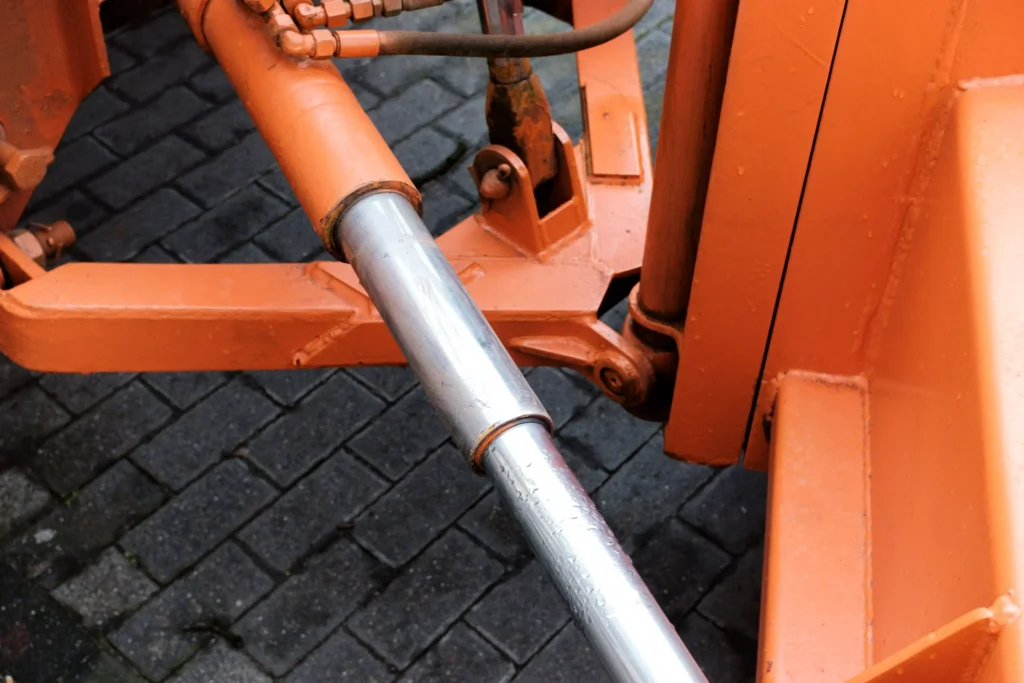
The conditions under which this configuration is most worth evaluating are when lateral space is limited, axial length can be increased, and a greater single-point output force is genuinely required. Axial refers to the direction of movement along the piston rod. You should first sketch out the maximum width, height and length permitted by the equipment, and then compare a standard large-bore cylinder configuration with a series configuration, rather than selecting a cylinder type first and then trying to squeeze it in.
For example, clamping mechanisms or press-fitting stations near a mould may be constrained in width by adjacent fixtures, whilst still being able to extend the power unit rearwards. In such cases, a series configuration is worth considering. Conversely, if the primary constraint of the equipment is the overall retracted length, or if rapid movement over long distances is required, increasing the cylinder section length and oil flow rate may exacerbate the problem. These are scenarios for evaluating design options and do not imply that any particular configuration has been validated on your specific equipment.
Taking the hypothetical area mentioned above as an example, 8,796 mm² is equivalent to the area of a perfect circle with a diameter of approximately 105.8 mm. This is merely a theoretical area comparison at the same pressure; it does not imply that the outer diameter of a series-connected assembly would be 80 mm, nor does it imply that it is entirely equivalent to an actual product with a 105.8 mm cylinder bore. Cylinder walls, end caps, mounting flanges, oil ports and maintenance clearance will all contribute to the external dimensions; you should request installation outline drawings for both candidate solutions and compare them alongside the estimated cycle times.
Assess Length, Alignment, Sealing, and Control Tradeoffs

Adding cylinder sections typically increases the overall retracted length and may also alter the installation loads and the space available for maintenance and repair. Alignment ensures that the axes of the cylinder barrel, guide components and rod members are correctly positioned relative to one another; when multiple pistons are rigidly linked, machining or installation deviations may translate into additional lateral forces, increasing friction and uneven wear. For example, one must not forcibly tighten the mounting bolts to ‘straighten’ the assembly in order to compensate for frame misalignment. Suppliers should verify coaxiality and installation requirements, whilst the equipment side should avoid subjecting the cylinder to lateral loads that should be borne by external guide rails.
The increased resultant force must also be transmitted through the rod ends, connecting components and mounting brackets. Buckling is the sudden lateral buckling and instability of a slender rod under compression; it does not necessarily mean that the material must first be crushed. You should verify the output rod and relevant load-bearing components based on the actual extension position, installation constraints and resultant force.
With regard to sealing and control, check the newly added piston seals and diaphragm rod seals, as well as the pressure differential on either side that they are capable of withstanding. If each power stage is supplied with pressure independently, leakage between adjacent chambers may alter the pressure relationship, though this may not necessarily manifest as external oil leakage. For example, when a design calls for only one power stage to be activated at a given stage, the chambers of the other stage are still changing in volume; appropriate oil supply, return or replenishment arrangements are required, and the oil ports must not simply be sealed off. During switching, checks must also be carried out to ensure that no pressure surges or sticking occur. The presence of multiple power stages does not in itself constitute a verified safety redundancy; one cannot simply assume that ‘if one fails, the other will continue to operate normally’ without conducting a thorough analysis.
Specify a Tandem Cylinder for the Actual Load Cycle
1. Describe the Load Over the Whole Cycle
A load cycle refers to the variations in load, speed, position and dwell time that a piece of equipment undergoes during a single complete operation. You should break down the ‘required force’ into stages such as approaching the workpiece, initial contact, working load, holding and return, and specify which stages require both force and speed, rather than simply stating a maximum thrust.
For example, a hypothetical press-fitting operation might require rapid approach during the idle stroke, high force only after contact with the workpiece, and a speed-dominated return stroke. Such requirements do not necessarily call for simultaneous oil supply to all power stages throughout the entire cycle, nor do they necessarily require the maximum flow rate and maximum pressure to occur simultaneously at all times. Whether power stages are activated in stages must be determined by the complete circuit design; simply stating ‘fast advance, slow press’ on a purchase order cannot be taken to mean that this has been implemented.
2. Turn the Requirements into Checkable Specifications
It is recommended that the following items be included in the request for quotation, and that suppliers be asked to clarify any assumptions and specify any information that needs to be provided by the equipment user. Theoretical calculated values, permissible operating values and delivery test values should be listed separately.
| Specification Item | What you should provide or confirm | Ambiguous phrasing to avoid |
|---|---|---|
| Force and Pressure | Thrust and tensile force at each stage; available pressure in each chamber; return oil back pressure and peak conditions | “There are two pistons, so the force will certainly be sufficient” |
| Speed and Flow Rate | Speed at each stage; oil supply flow rate; permissible cycle time; return oil capacity | “If we retain the original pump, the speed should remain the same” |
| Stroke and Dimensions | Combined output stroke, retracted and extended dimensions, lateral dimensions, maintenance clearance | “If the cylinder bore fits, it can be installed” |
| Connections and Control | Chamber numbers, port interconnections, pressure supply scheme, switching and make-up oil arrangements | “Plug off the chambers not currently in use” |
| Mechanical Load Capacity | Mounting method, load direction, off-centre loading conditions, permissible loads at rod end and frame | “As long as the cylinder body is not overpressurised, the mounting components are safe” |
| Environmental and Service Life Conditions | Hydraulic fluid, oil temperature, environmental contamination, cycles per hour, daily operating hours | “Treat it as a standard hydraulic cylinder” |
If position detection is required, specify whether the detection relates to the position of the common rod or the actual position of the external mechanism; if force output control is required, specify the permissible error and the positions to be measured. A single pressure reading from the common supply line is not necessarily sufficient to prove that all working chambers have reached the expected pressure, nor should it be directly treated as the actual force exerted on the workpiece without taking into account effective area and friction.
3. Agree on Validation Before Ordering
During the design verification stage, the area and force calculations for each chamber, the total supply and return oil flow rates, the load-bearing path and installation dimensions should be verified; during delivery acceptance, agreements should be made regarding pressure and leakage, reciprocating motion, as well as the actual configuration of switching, cushioning and detection functions. Cushioning is a mechanism designed to assist in deceleration as the stroke approaches its end; the presence of an additional piston within the assembly alone does not guarantee that end-of-stroke impact has been adequately addressed.
If verification of output force is required, suitable force-measuring equipment may be agreed upon, or the conditions under which calculations based on chamber pressures are applicable may be specified; passing a pressure test does not directly prove that the requirements are met throughout the entire load cycle. When submitting requirements to GY Hydraulic, please include the equipment layout diagram, motion sequence table, parameters of existing pumps and valves, and the target force-speed relationship to facilitate an assessment of whether the structure and circuit are compatible, rather than simply enquiring about ‘the price of a two-stage series cylinder’.
FAQs
Does tandem mean two cylinders connected by hoses?
No. Hose connections merely indicate the presence of a hydraulic circuit; they do not prove that the forces of the two pistons are combined at a common output end. The ‘tandem force-multiplying’ configuration described in this article requires the pistons to be mechanically linked via a common rod or other rigid connection. For example, where the discharge from the front cylinder supplies another independent cylinder, this constitutes a series circuit; you should examine the connecting components and the final output end in the cross-sectional diagram, rather than judging solely by the routing of the hoses.
Can tandem cylinders operate in both directions?
A double-acting design can be employed, meaning both extension and retraction are hydraulically driven; however, not all configurations provide the same force amplification effect in both directions. The areas occupied by the connecting rod and output rod may differ, and the power stages engaged in each direction may also vary. For example, the theoretical extension force and retraction force in the calculation example mentioned earlier are different. You should verify the effective area, pressure and return flow conditions for each direction separately; do not simply request a single ‘rated thrust’ figure.
Does a tandem cylinder double the stroke?
Generally, no. In a force-multiplying configuration, the pistons move along a common rod, and the output displacement does not simply add up based on the number of pistons. For example, if two pistons each travel 200 mm within their respective cylinder sections, the combined output stroke remains 200 mm. When selecting a model, you should verify the output stroke directly; if you require a long stroke with a short retraction length, you should separately evaluate telescopic or similar configurations.
Can the piston diameters differ in a tandem design?
Yes, provided that the mechanical connections, the dimensions of each section and the hydraulic circuit are designed accordingly; power amplification does not require all pistons to have the same diameter. For example, using different bore diameters will alter the output force and fluid consumption in each section, but will not cause the rigidly connected pistons to move at different speeds automatically. You should perform separate calculations for each chamber based on its actual bore diameter, rod diameter and pressure; you cannot simply multiply the area of one chamber by the number of pistons.
Can tandem chambers be supplied at different pressures?
This is possible with a specialised design, but standard shared oil supply configurations do not inherently support this capability. Different pressures require appropriate hydraulic isolation, pressure control and seal differential pressure design. For example, when one power stage operates at a lower pressure and another at a higher pressure, the total output should be calculated by summing the output of each chamber, whilst checking for inter-stage leakage, switching conditions and abnormal pressures. You should request the supplier to provide the corresponding schematic diagram; do not connect two pressure sources yourself for testing purposes.
Is a tandem cylinder self-locking?
No. Increasing the number of pistons does not automatically prevent movement following a loss of pressure, nor does it eliminate leaks from seals or valves. For example, whether a vertical mechanism retains its load after the oil supply is cut off depends on the complete circuit and mechanical constraints. You should clearly define the safe state following a loss of pressure and configure load holding, mechanical locking or other measures in accordance with equipment requirements; hydraulic position holding cannot replace the mechanical support required during maintenance.
Can a tandem cylinder replace a larger-bore cylinder directly?
It cannot be replaced directly simply because the theoretical thrust is similar. There may be differences between the two in terms of retracted length, extended dimensions, mounting loads, retraction force, supply and return flow rates, and control methods. For example, retaining the original pump may satisfy the force requirements of the new design but fail to achieve the original cycle speed. Before replacement, you should verify the dimensional drawings, force-velocity calculations in both directions, and the overall load-bearing capacity of the machine, and then confirm whether modifications to the pump, valves or mounting structure are required.
Does tandem construction guarantee synchronized external loads?
No. The fact that the internal pistons move in unison with the common rod merely indicates that they share a defined mechanical motion relationship; it does not mean that the positions of multiple external load points will always be consistent. For example, when a single output rod drives a wide beam, discrepancies may still arise on either side due to off-centre loading, beam deflection or guide rail play. You should clearly define the permissible positional differences externally and, where necessary, assess the guidance, structural rigidity or positional feedback; internal linkage must not be used as a substitute for verifying the synchronisation of the entire machine.
Choosing a Trusted Hydraulic Cylinder Manufacturer
From standard hydraulic cylinders to custom solutions, we help you improve equipment performance, delivery reliability, and batch consistency
Explore Rivmate Cases

Hey There, I'm Melody!
We are a hydraulic cylinder manufacturer. For over 20 years, we have focused on producing reliable hydraulic cylinders. Need a hydraulic cylinder solution? Feel free to contact us.