
Home / How to Bleed a Hydraulic Cylinder
How to Bleed a Hydraulic Cylinder
- Author: GY Hydraulic
- 20+ Years of Manufacturing
Bleeding a hydraulic cylinder involves expelling air trapped within the cylinder and associated oil lines via the routes specified for the equipment. The correct procedure depends on the cylinder’s design, mounting orientation and control circuit: where a dedicated bleed port is provided, use the specified device; where no bleed port is provided, bleeding may only be carried out via the prescribed reciprocating procedure if authorised by the manufacturer. Loosening the pressure hose coupling is not a universal method that can be applied indiscriminately.
If you are looking for ‘How to Bleed a Hydraulic Cylinder’, do not rush into repeatedly extending and retracting the piston rod. The piston rod is the component that extends from the cylinder body to drive the load; if it exhibits jerky movement, sluggish response or ‘bouncing’, this may be due to air, or it may stem from issues with the oil supply, valves or mechanical components. This GY Hydraulic guide will help you first identify the cause, then determine the appropriate bleeding method, carry out safety preparations, and verify whether the bleeding process has been effective.
Table of Contents
Recognize Trapped Air and Find How It Entered the System
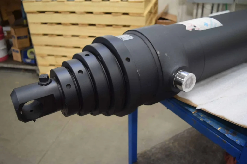
Air lock occurs when air becomes trapped at a certain point within a hydraulic cylinder or pipeline, forming a pocket of gas that has not been expelled in time. As air is more compressible than hydraulic oil, when oil is supplied, the air may be compressed first, with the piston rod only beginning to move afterwards. This manifests as sluggish movement, intermittent motion, or a sensation of pressing against a spring when force is applied. These phenomena merely indicate that you should check for air-related issues; they do not, on their own, prove that there is definitely air inside the cylinder. For example, misalignment during installation or uneven friction at seals may also cause jerky movement at low speeds.
First, review what actions were taken prior to the abnormality occurring. If a hydraulic cylinder has just been replaced, hoses disconnected or the fluid drained, residual air should be investigated as a priority; if the issue recurs during operation, a continuous air ingress must be investigated. Common causes include insufficient fluid level in the reservoir, a leaky suction line on the pump, and air being drawn in due to turbulence in the return flow within the reservoir. The suction side comprises the piping through which fluid enters the pump; at certain points, the pressure may be lower than the ambient pressure during operation, potentially causing air to be drawn in without any obvious external fluid leakage. Danfoss’s technical documentation on hydraulic fluids also lists a leaky suction line as one of the routes through which air can enter the system.
You may first note whether the anomaly occurs during extension or retraction, when the system is cold or hot, immediately after start-up or following continuous operation, and whether there is persistent foaming in the reservoir. For example, a spring-like movement during the first cycle after replacing a hose differs in its troubleshooting focus from foaming that occurs after a period of operation. Inspections of fittings and hoses should be carried out whilst the system is safely shut down; do not loosen connections one by one whilst the system is running in an attempt to locate the air ingress point.
Check the Cylinder Manual and Approved Bleeding Method
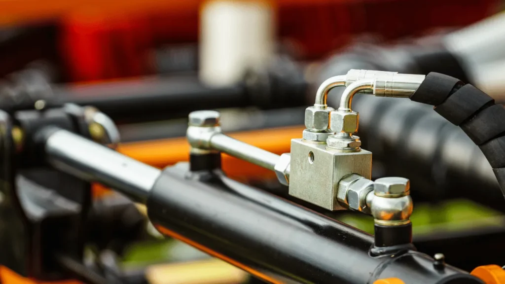
① Identify the Cylinder and the Complete Circuit
Before bleeding the system, consult both the hydraulic cylinder manual and the maintenance manual for the complete machine. It is not sufficient to check merely whether there are screws on the cylinder body, as the ability of the hydraulic fluid to carry away air also depends on the valves, pipework and installation position. A hydraulic circuit comprises the supply and return lines connecting the pump, valves, pipework and actuators. First, confirm the model using the nameplate, part number or drawings, and check that the documentation applies to the current version; if the equipment has been modified, also verify that the existing circuit matches the original drawings.
A single-acting cylinder is driven by hydraulic pressure in only one direction, with return relying on gravity, springs or other external forces; a double-acting cylinder is driven by hydraulic fluid for both extension and retraction. The bleeding paths and return conditions for the two types may differ. Stroke refers to the distance travelled by the piston rod from the retracted to the extended position. The piston is the component within the cylinder that moves in response to hydraulic pressure, driving the piston rod; for double-acting cylinders, it is necessary to confirm how the oil-filled spaces on both sides—that is, the cylinder chambers—are individually filled with oil and vented; one must not assume that both sides have been completed simply because oil has been discharged from one vent point.
② Confirm the Details Before Choosing a Method
Organise the requirements from the manual into the checklist below. For items that are not clearly specified, you should confirm them with the equipment manufacturer or hydraulic cylinder supplier; you must not rely on video footage of another piece of equipment to fill in the gaps.
| Items to be confirmed | Why it affects bleeding | Information you need to find |
|---|---|---|
| Bleed point | Standard plugs, adjustment screws and bleed screws may look similar | Illustrated location, part name, suitable tools |
| Equipment and hydraulic cylinder orientation | Air may become trapped at port locations where it cannot be purged | Permitted orientations, and whether special commissioning arrangements are required |
| Supply conditions | Excessive pressure or speed may cause sudden movement and component damage | Specified commissioning pressure, flow rate or speed control methods |
| Load and Motion Range | No-load, loaded, partial stroke and full stroke conditions must not be interchanged arbitrarily | Permissible loads, direction of movement, stroke and sequence |
| Completion and Reset Requirements | Draining a small amount of oil does not signify the end of the operation | Criteria for determination, shutdown procedures, tightening requirements and re-inspection items |
The position of the bleed port may also affect subsequent maintenance. For example, if a hydraulic cylinder is mounted high on a frame and the bleed port is obscured by a guard plate, the placement method used on a test bench cannot simply be replicated. One should first confirm a safely accessible bleed arrangement or an approved installation and commissioning plan; under no circumstances should the mounting pins be loosened on an ad hoc basis to rotate a loaded cylinder to a position that is ‘convenient for bleeding’.
③ Keep Model-Specific Instructions Within Their Scope
Secure Loads, Isolate Energy, and Relieve Stored Pressure
1. Make the Load Safe Before Opening the Circuit
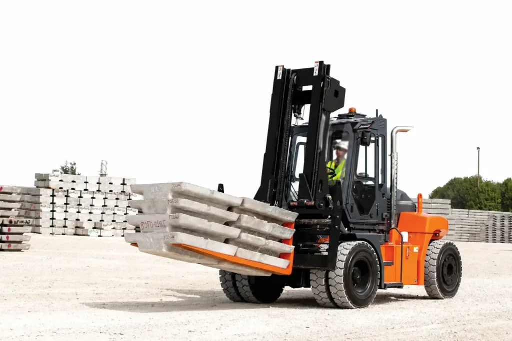
Secure any loads that may move before isolating the air supply. Raised working arms, carriages or clamping plates may move once the pressure is relieved. Where the equipment’s procedures allow it to be lowered to a stable and safe position, do so first; where it must remain raised, use mechanical supports or locking devices specified by the equipment manufacturer and with a suitable load-bearing capacity, whilst avoiding pinch zones. Do not rely on hydraulic cylinders, control valves or the fact that the load ‘does not appear to be sinking’ as reliable maintenance supports.
For example, when preparing to connect a bleed-off tool to a lifting cylinder—where bleeding the fluid could cause the overhead mechanism to lower—your first priority must be to secure the load and establish a safe working position.
2. Isolate and Verify the Relevant Stored Energy
Energy isolation involves disconnecting the equipment from any energy source that could cause it to start or move, and locking and tagging it in accordance with site procedures to prevent unauthorised restarting. Shutting down the pump does not necessarily mean there is no pressure in the cylinder. Load-holding valves—which restrict unintended movement of the load—may trap fluid within the cylinder chamber; accumulators, which store hydraulic energy, may continue to supply pressure to the circuit even after shutdown. Springs and raised loads may also continue to exert force.
Before fitting bleed-off tools, rerouting hoses or carrying out other preparatory work requiring proximity to pressurised areas, personnel with the appropriate competence must complete the following checks in accordance with the equipment procedures:
- Identify the power supply, engine, hydraulic pressure source and other relevant energy sources; shut down, isolate and prevent accidental restarting in accordance with procedures.
- Discharge residual pressure via the specified relief paths, including accumulators requiring separate treatment and sections isolated by valves.
- Verify at designated inspection points that the relevant sections have reached a condition permitting work, and confirm that the load will not move as a result of pressure relief.
A pump outlet pressure gauge reset to zero merely indicates the reading at the point to which it is connected; it does not prove that both cylinder chambers isolated by the valve have been depressurised. Furthermore, do not verify pressure by ‘loosening a coupling to see if oil sprays out’.
3. Separate Preparation from Controlled Operation
The bleeding process may sometimes require the restoration of oil supply or the movement of the hydraulic cylinder; this forms part of the prescribed commissioning phase and must not be interpreted as maintaining energy isolation whilst the equipment is in operation throughout the entire process. Prior to commencing commissioning, the position of tools, hoses, guards, personnel and control methods must be confirmed in accordance with the power restoration procedure; any arrangements requiring the movement of mechanical supports must also be carried out in accordance with the equipment procedures, and the cylinder must not be forced to move whilst bearing against the locking device.
For example, when one person controls the movement whilst another observes from a safe position, signals for start, stop and faults should be agreed in advance to ensure the observer does not enter the range of motion of the mechanism. When it is necessary to readjust connections or remove bleeding tools, the equipment must be returned to the maintenance state of being shut down, isolated and with pressure verified. Only in this way can a clear distinction be made between when movement is permitted and when it is safe to approach components.
Prepare the Correct Fluid, Reservoir Level, and Clean Equipment
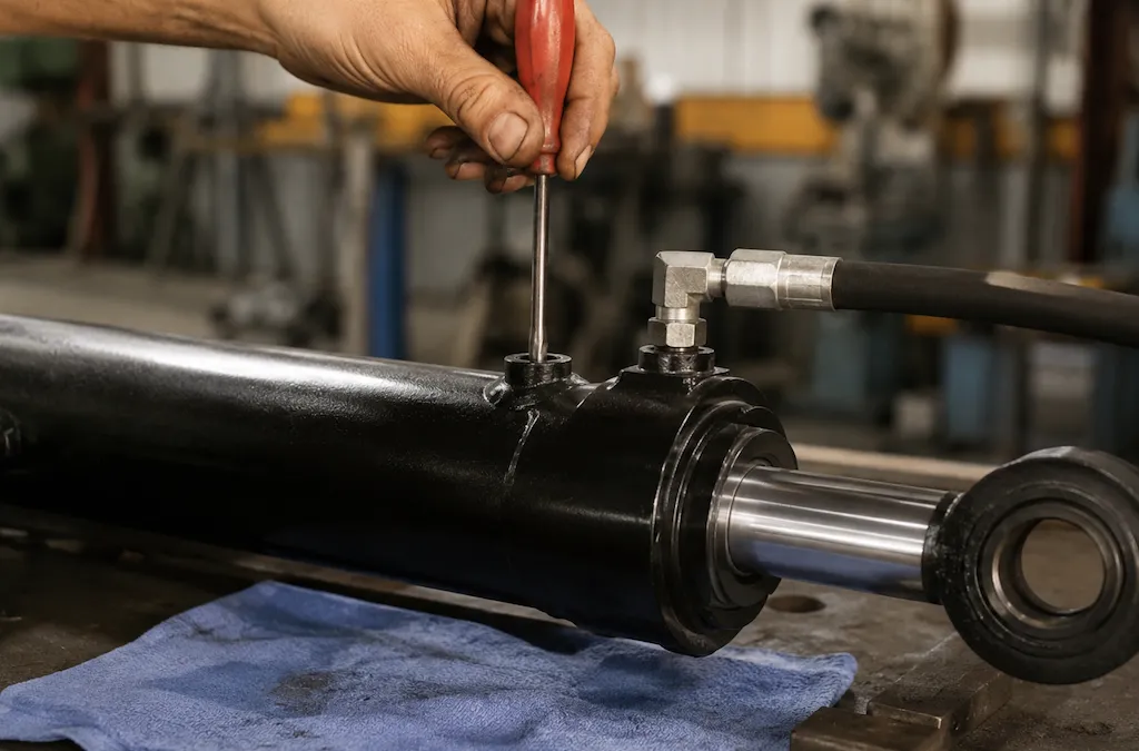
Use the hydraulic fluid specified for the equipment and check that the existing fluid is compatible with any top-up fluid. Viscosity can be simply understood as the ‘thickness’ of the fluid as it flows; it affects the pump’s suction, leakage and operational performance, but selection should not be based solely on the principle that ‘thicker is more stable’. Do not temporarily mix in other fluids or add defoamers yourself for the purpose of bleeding the system; if the fluid appears significantly abnormal, you should first assess whether sampling or replacement is required, rather than relying solely on bleeding procedures.
The reservoir fluid level must be checked under the equipment orientation, hydraulic cylinder position and oil temperature conditions specified in the manual. In standard single-rod cylinders, the volume of fluid in the reservoir changes as the cylinder extends and retracts; therefore, the same fluid level reading may be meaningless if taken outside the specified conditions. For example, in some systems, if the tank is overfilled when the cylinder is extended, the return flow upon retraction may cause the tank to overflow. You should first identify the correct conditions for checking the fluid level before topping up according to the scale; do not treat ‘topping up to the maximum line’ as a requirement applicable under all circumstances. Both excessive and insufficient fluid levels may lead to faults and risks; therefore, the manufacturer’s requirements must be followed.
Prepare cleaning materials to remove sediment, suitable oil-topping-up and filtration equipment, a collection container, personal protective equipment, and the specified bleeding tools. Where a drain hose is required, its fittings, pressure rating, temperature rating and compatibility with the fluid must meet the requirements of the equipment; ordinary transparent hoses must not be used as a substitute for pressure-rated tools. Clean the exterior of the bleed port before connecting the tool; the drained oil must be collected properly and must not be poured directly back into the reservoir. The fuel tank breather is a component designed to allow the fuel tank to exchange air as intended whilst filtering out external contaminants; it should also be inspected in accordance with the manual. The filler cap must not be left open for extended periods to ‘assist with venting’.
Bleed Through Designated Vents Where Provided
Confirm That the Vent Is Intended for This Task
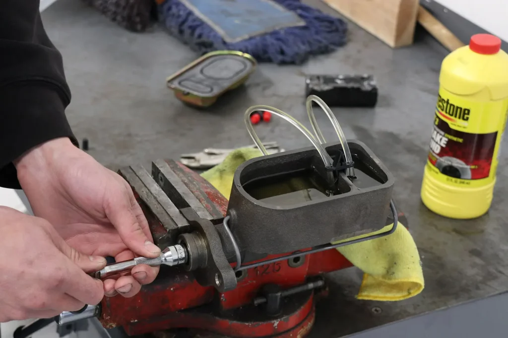
Operations may only be carried out in accordance with the relevant procedures for vent locations confirmed in the drawings or manual. Plugs on the cylinder head may seal internal oil passages, and nearby screws may be used for buffer adjustment. Cylinder-end buffering is a mechanism designed to assist in deceleration as the stroke nears its end; inadvertently adjusting these components may alter the end-of-stroke behaviour without resolving the air lock.
Double-acting cylinders may have venting points at both ends, or may feature other configurations. You must confirm which vent connects to which chamber, and whether the current installation orientation allows air to reach that vent. For example, if a vent is present but poorly positioned, it cannot be forced open by higher pressure; you should first confirm the manufacturer’s specified venting orientation or any specialised fittings.
Follow the Approved Venting Sequence
The following is a framework for checking and carrying out the specified venting procedure; specific opening amounts, direction of movement, pressure and closing sequence should be based on the instructions for that model. Do not commence trial operations without this information.
- Complete shutdown preparations. Handle the load as per the aforementioned procedure, isolate the power supply and verify relevant pressures, then clean the identified venting points.
- Connect the specified tools. Install venting couplings, hoses and collection containers as required by the equipment; secure any parts that may move; and ensure that the venting path is clear of personnel.
- Set up the venting equipment. Adjust the venting valve or screw to the specified position in accordance with the manual’s requirements. Do not fully remove screws that are permitted to be opened slightly, nor should you adopt the number of turns required for other models.
- Carry out controlled oil supply in accordance with the procedure. If operation is required, the operator must control the oil supply or movement from a safe position, using the specified pressure, speed and load conditions, whilst monitoring the equipment and the venting status.
- Verify and reset individually. Complete the venting of the relevant chambers in accordance with the manual, following the specified sequence for shutdown, depressurisation, shutdown and seal inspection. Before approaching the unit or removing tools, reconfirm that the system is in a safe condition permitting work.
Judge the Outlet and the Cylinder Together
For devices where the discharge of fluid is used as a criterion for assessment, you should verify, in accordance with the instructions, that the discharge has stabilised and that there are no visible bubbles, and then assess the effectiveness by observing subsequent movement. The initial discharge of a small amount of fluid does not necessarily prove that there is no residual air at higher positions or in another chamber; conversely, if only air is discharged, there is continuous splashing, or the specified fluid discharge does not occur after a reasonable delay, you should not wait indefinitely, but should stop to check the fluid level, the oil supply and the tool connections.
Use Manufacturer-Approved Cycling When No Bleeder Is Fitted
① Make Sure Cycling Can Carry Air Out
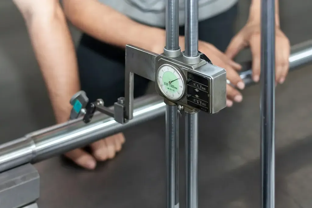
The absence of a bleed screw does not guarantee that air will be automatically purged after a few cycles. Reciprocating purging relies on the flow of hydraulic fluid to carry air out of the cylinder bore and direct it to the system’s designated discharge or separation point. If air is trapped in a space that cannot be flushed out, or if valves block the required path, simply increasing the number of cycles may not be effective.
First, confirm whether the manufacturer permits this method and the route by which the hydraulic fluid returns to the reservoir. For single-acting cylinders, also verify that the return force can safely complete the operation under the specified conditions; for double-acting cylinders, ensure that normal supply and return conditions are maintained in both directions. For example, a valve on a piece of equipment that closes when the power is cut off will not necessarily establish a venting path simply because you manually move the control lever.
② Use the Specified Motion, Not Repeated Stalling
Once preparations are complete and power has been restored in accordance with the commissioning procedure, check the following items in sequence:
- Orientation and Load: Maintain the state specified in the manual; do not remove a hydraulic cylinder whilst it is under load, nor adopt the inverted bleeding method used for portable tools.
- Pressure and Speed: Use the specified commissioning settings; change direction smoothly, and do not force bleeding by increasing pressure or moving the cylinder back and forth at high speed.
- Stroke and Sequence: Use partial or full strokes as required; reaching the end of the stroke does not mean it is permissible to continue supplying fluid or maintain pressure for an extended period.
- Observation and Pause: Monitor fluid levels, movement and unusual noises; when fluid top-up or connection adjustments are required, shut down the system as specified and resume the appropriate safe maintenance state.
‘Over-pressurisation’ occurs when the piston rod can no longer move but oil continues to be supplied, causing the pressure to rise. This does not automatically create a venting path and may also increase heat generation and impact forces. Hänchen warns that rapidly pressurising oil containing air may generate localised high temperatures and damage seals; therefore, high-speed, high-pressure testing is particularly unsuitable during the initial operation and venting phases.
③ Use Completion Criteria Instead of a Universal Cycle Count
The number of cycles serves to ensure effective venting and cannot replace the procedures and checks specified for the model. It does not imply that cylinders permanently mounted on equipment may be laid on their sides or operated in the same manner.
If operation remains unstable after completing the prescribed procedure, cease repeating the cycles and first check the orientation, hydraulic lines, fluid level and any ongoing sources of air ingress. Where a change in installation method or the use of an external venting device is required, the equipment owner must confirm the solution with the supplier. If the system also requires separate priming or venting prior to the initial start-up of the pump, the corresponding steps must be completed first; one must not rely on the movement of the hydraulic cylinder to substitute for the pump’s start-up preparations.
Recheck Fluid Level, Leakage, and Smooth Motion
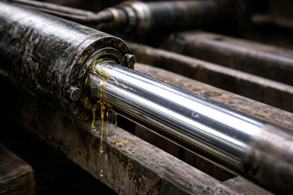
Once bleeding is complete, a re-inspection must be carried out under the specified conditions; do not rely solely on the fact that it ‘seems to be flowing freely’ at that moment. Return the equipment to the fluid level inspection position specified in the manual, wait as required for the fluid to stabilise before taking a reading, and use the specified fluid if a top-up is required. Do not mistakenly assume that the system has been sufficiently filled whilst there are still numerous air bubbles present or the fluid level appears artificially high, nor should you arbitrarily stipulate that all systems must be left to stand for the same number of minutes.
Observe the bleeding device, oil ports, fittings and the area around the rod seals from a safe position for any new leaks, and confirm that the tools have been removed in accordance with the procedure and that the bleeding points and protective guards have been reset. The rod seal is the component that prevents hydraulic fluid from leaking out along the piston rod. Do not touch pressurised leak points with your hands; pressurised fluid may penetrate the skin. If you suspect a hydraulic fluid injection injury, seek professional emergency medical treatment immediately and specify that pressurised fluid is involved.
Functional testing should first be carried out under the specified commissioning conditions to confirm that response, directional change and low-speed movements are normal; only then should operating conditions be gradually restored in permitted stages. For example, if operation is smooth at low speed under no load but remains noticeably jerky upon applying the specified load, it cannot be directly concluded that ‘there is just a little air left’. It is recommended to record the equipment’s orientation, oil temperature, load, direction of movement and performance both before and after bleeding, ensuring that the conditions for comparison are as similar as possible; improved movement merely indicates that the symptoms have been alleviated, and other functional checks specified for the equipment must still be completed.
Investigate Persistent Air and Stop When Conditions Are Unsafe
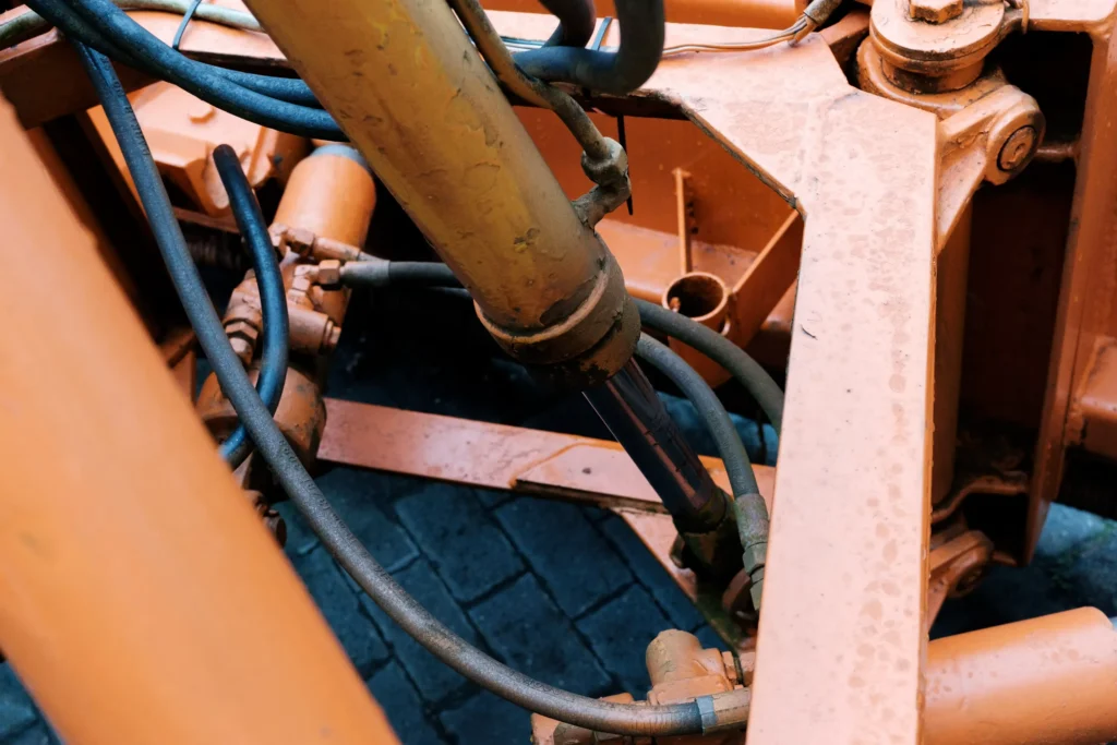
If the system returns to normal immediately after bleeding but begins to surge or bubble again during operation, the investigation should focus on persistent air ingress and oil supply conditions. Prioritise checking the oil level, the suction pipe and its sealed connections, and the oil return and air separation in the tank; also review whether an oil change or pipework modification has been carried out recently. For example, even if there are no oil stains on the floor, air ingress on the suction side cannot be ruled out; If a particular operation is particularly prone to recurrence, further inspection of the oil supply and load control in that area is required.
It is also important to distinguish between air ingress and cavitation. Cavitation, in this context, refers to the phenomenon where vapour cavities form in a liquid due to locally low pressure, which subsequently collapse when pressure is restored; this may be related to obstructed oil suction, excessively viscous oil or an insufficient oil supply, and cannot be rectified simply by bleeding air from the cylinder. Pump noise, cloudy oil or erratic operation do not necessarily indicate a single cause. If the cloudiness persists, moisture or other contamination should also be considered; where necessary, this should be determined through oil analysis rather than by adding defoaming agents on one’s own initiative.
Should unexpected load movement, sudden jerks, bulging or leaking hoses, abnormal temperature rise, persistent loud pump noise, or an inability to verify residual pressure occur, stop commissioning and keep personnel away from hazardous areas. You should provide the equipment manufacturer or GY Hydraulic with the hydraulic cylinder numbers, circuit diagrams, recent maintenance records, and details of the load and direction at the time the anomaly occurred, to assist in determining the next steps for inspection. Continuing to increase the number of cycles is no substitute for diagnosing an unknown fault.
FAQs
Does every hydraulic cylinder have a bleeder screw?
No. Some are fitted with dedicated bleeder screws, some use other bleeding mechanisms, and others are designed to remove air via the oil circuit in accordance with specified procedures. For example, the presence of a screw on the cylinder head does not necessarily mean it is a bleeder screw. You should check the relevant drawings or manual for the specific model; if you cannot locate a bleeder port, do not simply select a random standard plug to try.
Can bleeding air fix a worn piston seal?
No. The piston seal is located inside the cylinder and primarily prevents fluid from flowing from one side of the piston to the other; bleeding air cannot restore a worn or damaged seal. For example, whilst operation may become smoother after bleeding, if insufficient thrust or overheating persists, further investigation into the seal, fluid supply and control valves is required. The decision to repair a seal should be based on appropriate fault diagnosis; an improvement following air bleeding should not be taken as evidence that the seal has been repaired.
Is foamy reservoir oil the same as trapped cylinder air?
They are not the same thing. Foaming in the reservoir refers to the accumulation of bubbles on the surface of the oil, whilst trapped air in the cylinder refers to gas remaining in a specific location within the cylinder bore; there may also be tiny air bubbles dispersed throughout the oil that are difficult to see with the naked eye. They can co-exist, but one does not directly prove the other. For example, if the reservoir continues to foam, air-laden fluid may re-enter the system even if the cylinder has been purged at some point. You should check whether the foaming persists and investigate the fluid and the source of the air ingress, rather than focusing solely on the cylinder block.
Should a new cylinder be checked for trapped air?
You should confirm the oil-filling and air-bleeding requirements as per the manual before initial commissioning. The fact that a new cylinder has undergone factory testing does not guarantee that the entire system is free of air following transport, storage and connection. For example, connecting a hose that has not been filled with oil internally during installation may allow air to enter the relevant oil circuit. You should verify the start-up preparations before the first operation and use the specified commissioning conditions; you must not operate the system directly at high speed and full load simply on the grounds that it is ‘brand new’.
Can air return after successful bleeding?
Yes. Air may still enter if the suction side continues to draw in air, if the oil level is too low in certain orientations, or if the oil circuit is reopened during maintenance. Changes in pressure may also cause some of the air originally dissolved in the oil to form bubbles; therefore, recurrence does not necessarily stem from the same residual air pocket. For example, if the system operates normally temporarily after each oil top-up but bubbles reappear during operation, you should investigate why the oil level is dropping and whether air is being continuously drawn in, rather than simply repeating the bleeding procedure and concluding the repair.
Is cracking a pressurized hose fitting an acceptable bleeding method?
You must not manually loosen a standard hose fitting whilst it is still under pressure to bleed the system. Sudden release at the fitting may cause a jet of fluid, hose movement and unexpected displacement of the load; pressure may also remain inside the cylinder, isolated by a valve. For example, the fact that the pump has stopped does not guarantee that the connection is safe. If a specific model has a dedicated maintenance procedure for a particular connection point, this should be carried out by competent personnel in accordance with its isolation, depressurisation and safety requirements; in the absence of a clear procedure, operations should be halted to verify safety, and one must not simply ‘loosen it a little to see what happens’.
Can a telescopic cylinder need a different bleeding procedure?
Yes. Telescopic cylinders achieve a longer stroke by extending multiple sections of the sleeve; the hydraulic pathways and bleeding mechanisms between each stage may differ, so the methods used for standard single-stage cylinders cannot be directly applied. Parker’s maintenance documentation for telescopic cylinders provides separate instructions for manual bleeding of single-acting cylinders and for certain double-acting or self-bleeding designs. For example, whether bleeding via a complete cycle is permitted must be confirmed based on the specific design; you should first consult the model specifications and corresponding procedures, and must not alter the sequence of operations for each stage or adjust structural components on your own initiative.
Can trapped air make cylinder motion feel springy?
Yes, because air undergoes a noticeable change in volume when compressed, which may cause the movement to ‘compress briefly’ before proceeding. However, you should not verify this sensation by pushing the rod or compressing the load-bearing mechanism with your hand. For example, hose expansion, the action of an accumulator or the elasticity of mechanical structures may also produce similar behaviour. Observe the response from a safe position and assess it in conjunction with maintenance history and approved venting results; if the springy sensation persists, the cause must be investigated further—it cannot be assumed to be air based on sensation alone.
Choosing a Trusted Hydraulic Cylinder Manufacturer
From standard hydraulic cylinders to custom solutions, we help you improve equipment performance, delivery reliability, and batch consistency
Explore Rivmate Cases

Hey There, I'm Melody!
We are a hydraulic cylinder manufacturer. For over 20 years, we have focused on producing reliable hydraulic cylinders. Need a hydraulic cylinder solution? Feel free to contact us.