Home / Hydraulic Cylinders for Mining: Selection Guide
Hydraulic Cylinders for Mining: Selection Guide
- Author: GY Hydraulic
- 20+ Years of Manufacturing
When selecting hydraulic cylinders for mining, you must first clarify the specific function they will perform on the equipment, and then verify the load, installation space, on-site environment and the consequences of failure. Hydraulic cylinders are actuators that convert the pressure of hydraulic fluid into linear thrust or pull; two cylinders with similar external dimensions may be suitable for entirely different operating conditions due to differences in internal structure, piston rod dimensions or sealing materials.
This GY Hydraulic selection guide follows the sequence of actual procurement and engineering verification to help you transform the vague requirement of ‘needing a heavy-duty cylinder’ into verifiable technical specifications. You do not need to understand all the calculations from the outset, but you should know which parameters must be measured and which issues require confirmation from the equipment manufacturer or hydraulic cylinder supplier.
Table of Contents
Match Cylinder Design to Mining Equipment and Duty
First, clearly define the ‘equipment, motion and direction of force’, then select the cylinder configuration. For example, the boom cylinders on mining excavators must withstand thrust and tensile loads whilst the mechanical angle is constantly changing; the lifting cylinders on tipper lorries must be selected taking into account the body’s centre of gravity and the lifting geometry; whilst for drilling rig feed cylinders, attention must be paid to the feed force, retraction force and the smoothness of low-speed movement. Load-bearing components used in underground support systems also have specific system requirements; they cannot simply be replaced by standard lifting cylinders merely because the dimensions are similar.
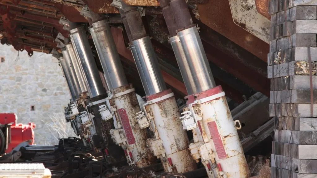
A double-acting cylinder is a hydraulic cylinder driven by hydraulic fluid in both the extension and retraction strokes, making it suitable for operations requiring active control in both directions of movement. A single-acting cylinder is driven by hydraulic pressure in only one direction, whilst the return in the other direction relies on gravity or other external forces; it is unsuitable if the equipment lacks a reliable return force in certain orientations. Multi-stage telescopic cylinders consist of multiple sections of the cylinder barrel extending sequentially; they are suitable for lifting applications where retraction space is limited and the working stroke is long. However, as the effective area varies between stages, thrust and speed may change with each stage, and the parameters of the longest stage cannot be used to represent the entire stroke.
You may also encounter welded and tie-rod designs: the former connects certain pressure-bearing components via welding, whilst the latter uses external tie-rods to clamp the end caps to the cylinder barrel. The cylinder barrel is the pressure-bearing tube that houses the piston and hydraulic fluid, whilst the end caps seal its ends. These two terms describe structural connection methods and may co-exist with functional classifications such as ‘double-acting’. Do not equate ‘welded’ directly with ‘suitable for all mining applications’, nor assume that all welded cylinders cannot be dismantled for repair. When requesting a quotation, it is more useful to first submit a photograph of the installation location and a schematic diagram of the operation, specifying whether bidirectional force output is required, whether the cylinder will be under prolonged load, and whether the entire cylinder can be removed on site, rather than simply stating ‘heavy-duty mining use’.
Calculate Loads, Pressure, Stroke, and Duty Cycle
1. Start with the Force at the Cylinder
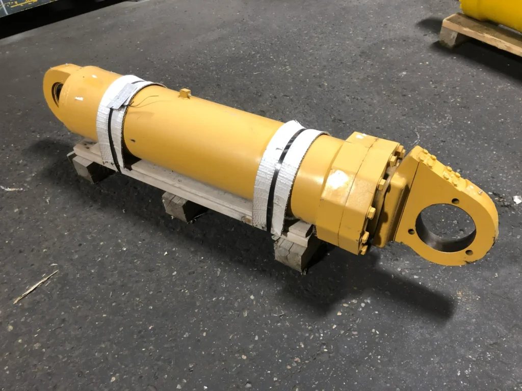
The weight of the equipment being moved is not equivalent to the force that the hydraulic cylinder needs to exert. The piston rod is the component that extends from the cylinder body and connects to the mechanism. If it lifts the working arm via an articulated mechanism, you must take into account the lever arm—that is, the perpendicular distance from the line of action of the force to the pivot axis. The shorter the lever arm, the greater the force the hydraulic cylinder typically needs to exert to overcome the same rotational torque.
For example, suppose that in a given configuration, the load exerts a torque of 40 kN·m on the pivot axis, and the vertical lever arm of the hydraulic cylinder is 0.4 m. Based on a static equilibrium calculation, the required cylinder force is 100 kN; when the lever arm is reduced to 0.2 m, the required cylinder force becomes 200 kN. kN stands for kilonewton; 1 kN = 1,000 N, which is a unit of force; kN·m represents the torque resulting from the product of force and lever arm. This is merely a demonstration of the geometric relationship and does not yet account for the mechanism’s own weight, friction, acceleration or impact. You should have engineering staff examine the entire range of motion to identify the most unfavourable configuration; calculations must not be based solely on the equipment’s position when stationary.
2. Check Both Extension and Retraction
The piston is the component within the cylinder barrel that moves in response to hydraulic pressure, driving the piston rod. The bore diameter is the internal diameter of the cylinder barrel and determines the total effective area of the piston. For a common double-acting single-rod cylinder, the rodless chamber is the side of the piston without the rod; the rod chamber has a smaller effective area because the rod occupies space. Consequently, at the same pressure, the theoretical pulling force in the retraction direction is typically less than the theoretical thrust in the extension direction. Parker’s selection guide also treats the thrust and pull directions, effective area and rod diameter as combined selection criteria.
Preliminary calculations can be made using the following relationships, where D is the cylinder bore diameter and d is the rod diameter:
- Rodless chamber area: A₁ = πD² ÷ 4.
- Effective area of the rod chamber: A₂ = π(D² − d²) ÷ 4.
- When back pressure from the return line and friction are neglected, the extension thrust F ≈ pA₁, and the retraction pull F ≈ pA₂.
If pressure is expressed in MPa (megapascals, a unit of pressure) and area in mm², the calculated force is in N, as 1 MPa = 1 N/mm². The following is a set of hypothetical calculation examples; these are not product specifications or test results: cylinder bore 100 mm, rod diameter 60 mm, inlet pressure 20 MPa, with the pressure in the other chamber and friction temporarily ignored.
| Item | Calculation Result | How You Should Interpret This |
|---|---|---|
| Rodless Chamber Area | Approx. 7,854 mm² | Used for preliminary calculation of extension thrust. |
| Effective Area of Rod Chamber | Approx. 5,027 mm² | Used for preliminary calculation of retraction tensile force. |
| Theoretical Extension Thrust | Approx. 157 kN | Cannot be directly treated as the permissible working load. |
| Theoretical Retraction Pull Force | Approx. 101 kN | Must be verified separately when retraction force is required. |
During actual extension, the more complete force relationship is: **Net thrust ≈ pressure in the rodless chamber × A₁ − pressure in the rod chamber × A₂ − frictional resistance. ** Return back pressure is the pressure generated by resistance encountered when the hydraulic fluid returns; it also offsets part of the output force. The pressure at the pump outlet is not necessarily equal to the pressure at the cylinder port; therefore, you must confirm the available pressure at the cylinder port, losses in the piping and valves, and the setting of the main relief valve. The main relief valve is designed to limit the pressure in the circuit it protects; its set value must not be treated as the pressure that is always available at the cylinder port.
3. Match the Stroke and Speed to the Complete Cycle
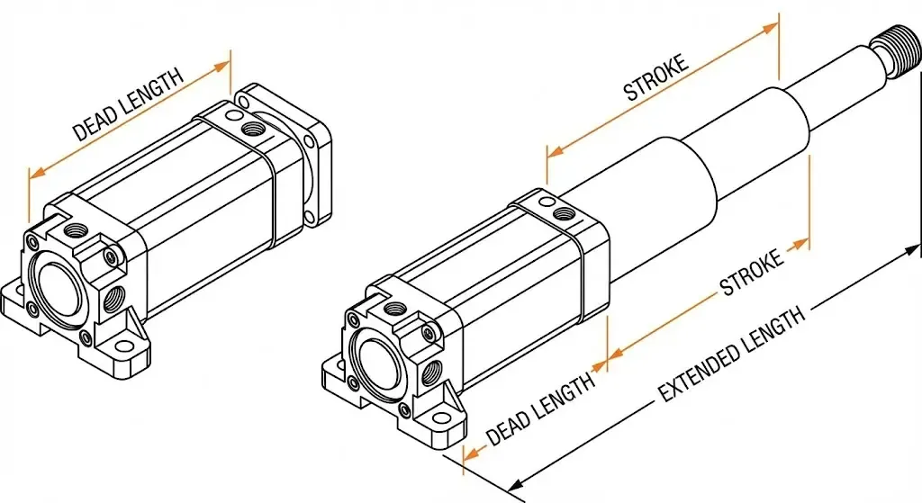
Stroke refers to the distance travelled by the piston rod from the fully retracted to the fully extended position. In addition to verifying the stroke, you should also check the centre-to-centre distance between the two mounting pin holes in both the retracted and extended positions, and ensure that there is no interference between the cylinder body, fittings and hoses throughout the full range of motion. In principle, a hydraulic cylinder should not be arbitrarily used as a mechanical hard stop; if the design requires it to function as an end-of-stroke stop, it must be specifically verified in accordance with the corresponding kinetic energy and loads.
Flow rate is the volume of oil entering the cylinder per unit of time. Neglecting leakage, the speed is approximately equal to the flow rate divided by the effective cross-sectional area. Using the hypothetical cylinder described above, if the actual flow rate into the rodless chamber is 30 L/min and the extension speed is approximately 64 mm/s, a 500 mm extension stroke would take approximately 7.9 s to complete. This result describes only the ideal constant-speed phase; the actual time is also affected by start-up, deceleration, load and flow distribution.
The operating cycle should record the times for extension, dwell, retraction and waiting, as well as the number of cycles per hour and the daily operating duration. For example, ‘one cycle per minute, with a 40-second pressure hold per cycle’ and ‘one cycle per minute, with unloaded reciprocation per cycle’ place different demands on temperature rise, seals and fatigue. Fatigue is the process by which damage gradually develops and propagates in a material following repeated loading. You should provide the supplier with the load-over-time profile, rather than merely a description of ‘continuous operation’; nor should you apply a so-called ‘mining safety factor’ across the board without prior analysis.
Design for Shock Loads, Buckling, and Mounting Alignment
Identify Where the Shock Comes From
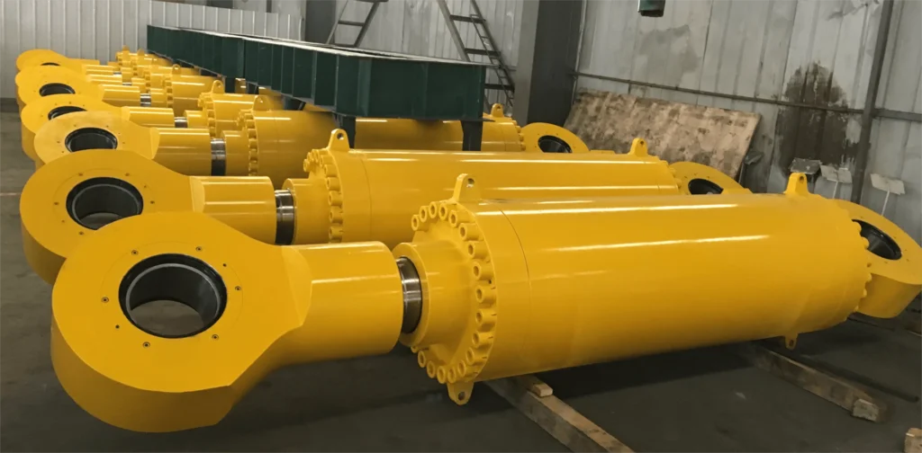
A shock load is a sudden increase in force over a short period of time, such as a bucket striking hard rock, a lifting mechanism coming to an abrupt halt, or a pin clearance being rapidly compressed. You need to distinguish whether the shock stems from deceleration at the end of a normal stroke or from an external collision during the stroke, as the approaches to addressing these are different.
End-of-stroke buffering is a mechanism that restricts oil flow as the stroke nears its end to help slow moving parts; it is suitable for end-of-stroke deceleration tasks within its design parameters but cannot replace protection against external impacts. For shocks occurring during the stroke, engineers must also examine the forces acting on the mechanism, local pressure protection, valve response and permissible flow rates. The main relief valve may not necessarily protect cylinder chambers isolated by other valves, nor may it be able to limit all transient peaks in a timely manner.
If an old cylinder frequently fails during the same operation, you should first document the position, speed and operating sequence at the time of failure, then have qualified personnel record dynamic pressures at the relevant cylinder ports. Ordinary pressure gauges may not clearly display very short pressure spikes. Asking the supplier to distinguish between normal operating pressure, potential peak pressures and their duration is a more effective approach to addressing the root cause than simply requesting a ‘thicker cylinder barrel’.
Check Rod Stability at the Critical Extension
Buckling is a phenomenon whereby a slender rod suddenly bends sideways and becomes unstable when subjected to compressive forces; it does not necessarily occur only after the steel has been crushed. Long-stroke cylinders require particular attention when the piston rod is extended significantly and is subjected to thrust; however, the actual most dangerous position must still be determined in conjunction with how the thrust varies with the mechanism’s orientation.
For an ideal slender compression rod, all other conditions being equal, a doubling of the effective length reduces the theoretical critical buckling load to one-quarter of its original value. The effective length here is related to end constraints and mounting methods and cannot be directly equated with stroke. Practical hydraulic cylinders also involve the cylinder barrel, guide supports, clearances and initial bending; therefore, supplier selection methods or engineering calculations appropriate to the specific structure should be employed.
A practical procurement requirement is to ask the supplier to verify the rod diameter and stability based on the actual installation method, the maximum relevant extension and the corresponding compression load, rather than merely confirming the rated pressure. Increasing the rod diameter may improve stability, but it also reduces the area of the rod chamber and lowers the retracting force at the same pressure; therefore, it is necessary to refer back to the push-pull calculations discussed earlier for verification.
Let the Mounting Follow the Motion
Lateral loads are forces acting perpendicular to the piston rod axis. Standard hydraulic cylinders are primarily used for axial thrust and pull; if the working mechanism uses them as guide rails, or if the mounting bracket is misaligned, this can easily lead to increased wear on guide components, rod bending and seal damage. Guide components are parts that support and guide relative motion, reducing direct metal-to-metal contact.
For example, when a boom rotates, the cylinder body usually needs to swing along with the mounting pivot point. If one end requires rotation but is rigidly fixed, the piston rod may be forced to bend during a certain portion of its stroke. Spherical bearings can accommodate angular deflection within the design limits, but cannot compensate for arbitrary degrees of frame deformation or pin misalignment. During installation and acceptance testing, safety checks should be carried out in accordance with the equipment specifications at the retracted, intermediate and extended positions to confirm that there is no jamming, interference or abnormal uneven wear; the cylinder must not be ‘forced into position’ by tightening bolts or forcibly pushing the pin into place.
Protect Rods and Seals from Dust, Water, and Corrosion
① Match the Wiper to the Contamination
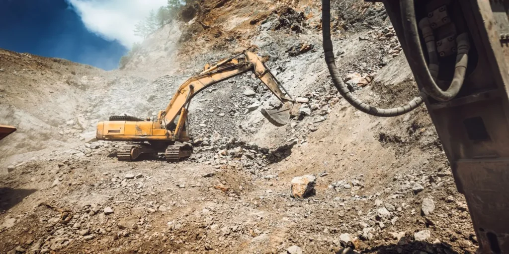
Seals are used to limit fluid leakage and help isolate different chambers; dust seals, on the other hand, are located where the piston rod enters the cylinder and are primarily responsible for scraping away external contaminants from the rod surface. You cannot expect a standard dust seal to simultaneously address issues such as dry rock dust, sticky slurry, repeated flushing and corrosive water.
| Site Conditions | Key Considerations for Selection | Commonly Overlooked Issues |
|---|---|---|
| Dry rock dust, high concentration of fine particles | Dust-seal lip design, material wear resistance, condition of the rod surface | Dust adheres to an excessive oil film and is subjected to repeated friction during movement |
| Sticky sludge and debris prone to accumulation | Scraping capability, drainage space, installation orientation | Scraped-off sludge has no space to drain and is forced back onto the rod surface |
| Frequent flushing or contact with water | Waterproof dust-scraping structure, material water resistance, shield drainage | Flushing water directly impacts the seal inlet, causing prolonged water accumulation inside the shield |
| Corrosive mine water, saline environments | Rod surface anti-corrosion system, cylinder body coating, protection of exposed joints | Protection limited to the cylinder body paint, neglecting the rod surface and connection points |
You could provide the supplier with a photograph of the site prior to cleaning, specifying whether the contaminants are fine powder, sand grains or sticky sludge, and whether water immersion is present. This information will help determine whether a more robust scraper structure or additional protection is required, rather than simply selecting the hardest scraper material based solely on the fact that ‘mine conditions are harsh’.
② Treat the Seals as a System
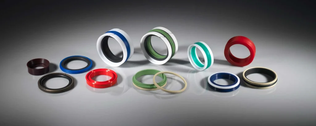
Dust seals, rod seals and guide components must work in concert. Rod seals are responsible for controlling fluid leakage between the rod and the cylinder head; in certain high-load applications, buffer seals may also be used to mitigate pressure fluctuations on the main rod seal, though their suitability depends on the overall seal configuration. Simply replacing a single seal with a tighter one may increase friction and heat generation, and may not necessarily improve service life.
For example, if an old cylinder exhibits significant uneven wear on one side alongside recurrent oil leakage, you should first check the alignment, pin clearance and guide supports before determining whether the seal configuration requires adjustment. Otherwise, the new seals will still operate under the same conditions of uneven loading. Similarly, the control of external oil films should be assessed based on the specific sealing system; one must not automatically assume that any visible oil film on the rod surface indicates the same type of leakage fault.
③ Keep Protection Accessible and Drainable
Protective plates or suitable guards can reduce the impact of flying stones striking the piston rod directly; however, during design, clearance, drainage and cleaning space must be checked throughout the entire stroke. If a flexible guard is torn and remains covered in mud and sand for an extended period, it may actually allow contaminants to remain in continuous contact with the rod surface. Therefore, the decision to fit a guard should depend on the risk of impact, available space and on-site maintenance conditions, rather than simply on whether or not the rod is covered.
External protection cannot replace proper hydraulic fluid cleanliness management. For example, if a fitting containing sand particles is refitted during maintenance, contaminants will still enter the hydraulic circuit, even if the correct dust seal has been selected. You should require suppliers to confirm hydraulic fluid cleanliness targets based on the requirements of sensitive components, valves and seals within the system, and incorporate filter element maintenance, pipe cleaning and the investigation of mineral water ingress into the reservoir into on-site management; do not apply a single cleanliness figure that is suitable for all mining machinery.
Specify Materials, Coatings, and Temperature Compatibility
State material requirements as ‘material grade, condition and operating conditions’; do not simply specify ‘high-strength steel’. For cylinders subjected to cyclic loading or cold-start operation, you must consider the strength, toughness and heat treatment condition of the rods and connection points; Toughness can be simply understood as a material’s ability to resist crack propagation and sudden fracture, whilst heat treatment alters material properties by controlling heating and cooling. For example, when assessing the suitability of connection ends with pin holes in low-temperature environments, one cannot rely solely on room-temperature strength specifications. For welded structures, an evaluation must also take into account the material’s weldability and joint quality; design verification cannot be substituted by simply increasing the external dimensions of the weld.
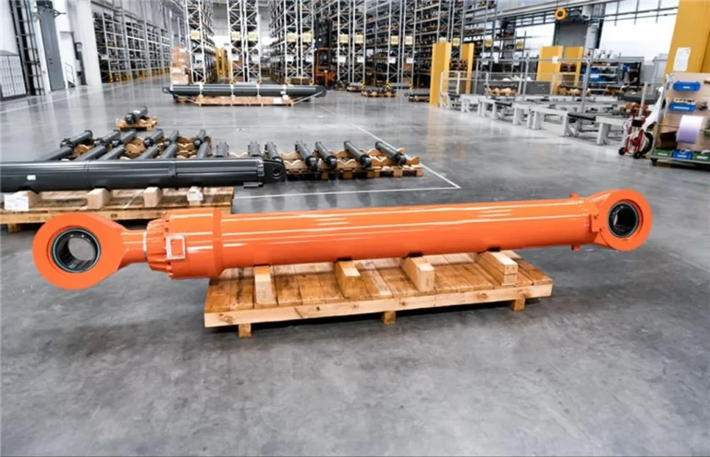
Coatings on rod surfaces must take into account wear, corrosion and sealing fit simultaneously. Hard chrome plating is a common surface treatment for rods, but this does not guarantee immunity to corrosion during prolonged contact with mine water; higher-grade corrosion protection systems must also be selected in consideration of contaminants, the base material and repair conditions. You may require the supplier to specify the coating type, thickness requirements, surface roughness and acceptance criteria in the drawings. Surface roughness describes the minute undulations on the rod surface; a smoother surface is not necessarily more suitable for sealing. If a salt spray test report is provided, you must verify that the treatment system applied to the test specimen is consistent with that of the actual rod components to be delivered; the duration of the salt spray test cannot be directly converted into the service life in a mining environment.
Temperature compatibility must be assessed in relation to cold start conditions, operating oil temperature and local heat sources, and must be verified in conjunction with the hydraulic fluid to be used. Water-glycol is one of the water-based, flame-retardant hydraulic fluids; the requirements for seals and metallic materials cannot be directly adopted from mineral oil applications. You should provide the brand and model of the hydraulic fluid, the minimum start-up temperature and the maximum stable operating oil temperature, and require the supplier to confirm the suitability of the complete set of seals and their internal materials. For example, in cylinders located close to the engine heat source, even if the reservoir temperature is normal, exposed sealing areas may be subjected to higher temperatures; when switching to so-called ‘high-temperature-resistant seals’, verification of low-temperature and medium compatibility must not be overlooked.
Integrate Load Holding and Equipment Safety Requirements
Define What Happens When Power or a Hose Is Lost
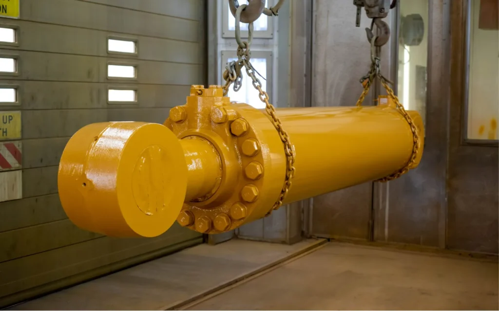
Load holding refers to the restriction of unintended load movement following the cessation of operation. For lifting carriages, drill booms or support structures, you should specify at the cylinder selection stage: where the load should be held once the pump stops, the control power is lost or a hose fails; what movements are permitted; and how to restore the position or lower the load safely. This requires the combined action of the hydraulic cylinder, valves, piping and the overall machine control system.
Sufficient thrust does not guarantee that the load can still be safely supported after the supply pressure is lost. For example, the fact that a hydraulic cylinder can lift a carriage does not prove that it can maintain its position after a supply hose ruptures. Risk assessments should cover the actual hydraulic circuit and installation location, rather than merely examining the strength of the cylinder body. ISO 4413, which covers general rules and safety requirements for mechanical hydraulic systems and their components, can serve as one of the bases for system design in applicable projects; specific projects must still confirm the requirements of the complete machine and the site of use.
Choose Holding and Lowering Functions Separately
A hydraulically controlled check valve is a valve that normally prevents reverse flow but can be opened by control oil pressure; a balancing valve, on the other hand, can be used to limit the load from causing the actuator to move too rapidly and to assist in controlling the descent of the load. Both may be involved in position holding, but they cannot be interchanged arbitrarily simply because they both ‘lock the oil’.
| Problem to be solved | Solutions to be discussed | Selection criteria |
|---|---|---|
| Position holding during stoppage | Suitable hydraulically controlled check valve or other position-holding solution | Verify opening pressure, leakage performance and pressure protection for trapped fluid |
| Load descends under gravity | Balance valve and descent control suitable for the circuit | Verify load range, flow rate, return line back pressure and motion stability |
| Limiting load movement following supply line failure | Cylinder port load-holding configuration designed for the specific failure scenario | The connection between the valve and the cylinder remains a pressure boundary requiring inspection |
Hydraulically controlled check valves are not suitable for the smooth control of load-driven lowering movements; load-holding valves should also be positioned as close as possible to the actuator to minimise unprotected sections resulting from pipeline failure.
When selecting valves in practice, you must also ensure that the designer verifies the pilot ratio—that is, the proportional relationship between the control pressure and the valve’s opening—as well as the impact of pressure changes upstream and downstream of the valve. The same valve model or pressure setting must not be applied to all mining cylinder liners; ultimately, start-up, stop and lowering performance must be verified under no-load and full-load conditions, as well as at different mechanical angles.
Include Trapped Pressure and Maintenance Support
Oil trapped within the cylinder chamber may expand due to heat, or loads may be transferred between different effective areas, both of which can generate pressures that require separate assessment. Therefore, load-holding solutions must also account for thermal expansion relief, potential pressure amplification, and controlled pressure relief pathways in the event of power loss. Simply installing the valve close to the hydraulic cylinder does not automatically resolve these issues.
When entering the area beneath a raised work implement for maintenance, mechanical supports or locking devices capable of withstanding the corresponding load must be used in accordance with the equipment specifications, whilst isolating the power supply, releasing and verifying the residual hydraulic energy; if an accumulator is present, the energy stored therein must also be managed in accordance with established procedures. Accumulators are components that store hydraulic energy and may continue to supply pressure to the circuit even after the pump has been shut down. Do not assume that the fact that the equipment has been ‘shut down’ or is ‘fitted with a hold-open valve’ constitutes proof that the maintenance area is safe.
Plan Inspection, Rebuilding, and Spare Parts Availability
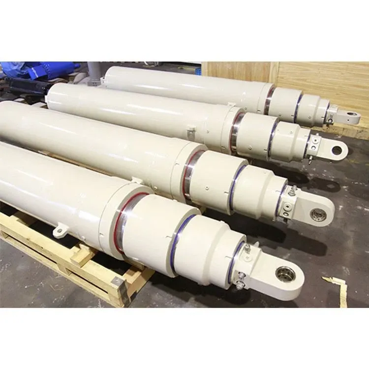
When selecting a model, you must confirm how it will be dismantled and repaired in the future, and how long it will take to obtain spare parts. For example, even if a cylinder meets the performance requirements, if the cylinder head must be removed after first dismantling an adjacent assembly, on-site downtime may increase significantly. You should verify the space available for dismantling after installation, the conditions for moving the entire cylinder, whether the cylinder head is removable, and whether special tools and fastening requirements can be met.
An inspection programme could begin with a visual check of the rod surface, external leaks and the condition of connecting components at a safe, visible location during each shift, followed by the determination of further inspection intervals based on the equipment manual, the level of on-site contamination and fault trends. Rather than stipulating that seals be replaced uniformly after all cylinders have operated for the same number of hours, it is better to record the location of faults, operating time and the conditions under which they occurred. For example, if scuff marks appear on the same side repeatedly whilst the rod is extended to a considerable extent, it is worth checking the guides, pins and installation alignment first, rather than continuing to replace the seals repeatedly.
The spare parts list should, at a minimum, link the serial number of the complete cylinder to the drawing version, seal kit, guide components and key connecting parts. A seal kit is a set of replacement seals configured specifically for that cylinder; when verifying it, in addition to dimensions, one must also check the materials and the suitable hydraulic fluid. For critical cylinders where downtime has a significant impact, you can compare the ‘local repair turnaround time’ with the ‘actual delivery time for a new cylinder’ to decide whether to stock seal kits, keep complete cylinders in rotation, or both. The suitability of reconditioning should be determined based on the results of the disassembly inspection of the rod face, cylinder barrel, connection points and dimensions; it should not be based solely on a lower repair quotation.
Validate Supplier Capability with Testing and Traceability
Suppliers are required to ensure that the statement ‘can be manufactured’ is reflected in the drawings, inspection items and corresponding records. Traceability refers to the ability to trace back the material, manufacturing and inspection information relating to a product via its cylinder serial number or production batch. For example, if a drawing specifies a particular type of bar stock and its heat treatment condition, the delivery documentation must be able to be traced back to the relevant material and heat treatment records; for high-consequence failure locations, welding quality control measures and whether non-destructive testing is required should also be agreed in advance. Non-destructive testing is a method of inspecting certain internal or surface defects without damaging the component; the methods used and the locations inspected are determined by design and quality requirements.
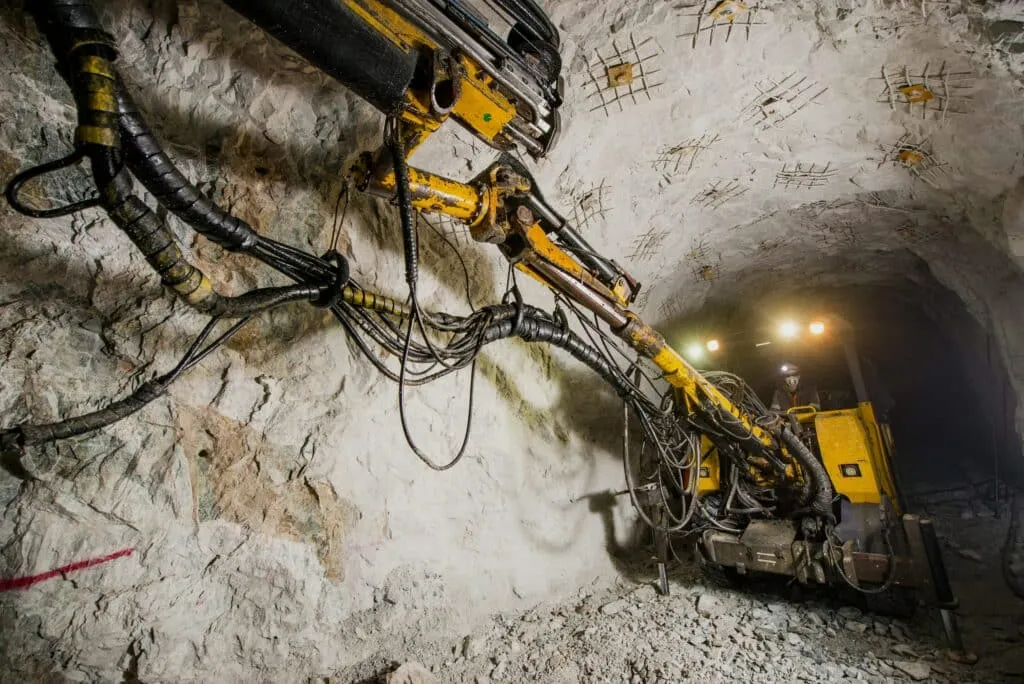
In quotations or technical agreements, it is recommended that the following items be confirmed one by one. These constitute procurement verification points; the specific items and acceptance criteria should be agreed upon by both parties and must not be interpreted as requiring all mining cylinders to undergo the same set of tests:
- Installation and Dimensions: Cylinder bore, rod diameter, stroke, centre-to-centre distance of pin holes, port locations and critical fit dimensions shall be as per the approved drawings.
- Pressure and Leakage: Specify the test medium, pressure, pressure hold time, oil temperature, test locations and acceptance criteria; ensure that test reports correspond to the individual cylinder serial numbers.
- Motion and Function: Test reciprocating motion, low-speed performance and buffering in accordance with the agreement, as well as the functionality of the fitted valves and position detection systems.
- Verification under Special Operating Conditions: As agreed based on risk assessment, specify fatigue, shock, low-temperature, coating corrosion resistance or complete machine load tests, and clarify which are to be carried out by the supplier and which by the equipment owner.
ISO 10100 specifies acceptance and functional testing for hydraulic cylinders and may serve as the basis for acceptance where applicable and mutually agreed; however, passing a single factory pressure test does not prove that the hydraulic cylinder has been validated for the entire service life in mining conditions, all shock conditions or the safety of the complete machine. You should ask the supplier to specify what the delivery tests cover and what still needs to be verified by the equipment owner.
When submitting a project to GY Hydraulic, it is recommended that you also provide the original cylinder drawings or part numbers, a description of the equipment’s operation, key loads and pressures, installation dimensions, the type of hydraulic fluid, and information on the mining environment, before confirming the scope of design and delivery inspection item by item. This information is far more helpful than simply stating ‘we need a more durable mining cylinder’ in enabling both parties to determine whether the solution is suitable for your equipment.
FAQs
Are mining cylinders interchangeable across equipment brands?
This cannot be determined solely on the basis of brand or external appearance. Cross-brand replacement requires a item-by-item verification of installation dimensions, cylinder bore and rod diameter, stroke, pressure, oil ports, force direction, hold-open valves and control feedback, amongst other factors, and must be subject to relevant engineering approval. For example, if two cylinders can both fit onto the same pin but have different rod diameters, this may alter the retraction force and movement speed. You should first obtain the original cylinder part number and drawings to confirm equivalence before purchasing; ‘fitting into the mounting’ is merely one of the conditions for replacement.
Can a mining cylinder be rebuilt rather than replaced?
Yes, but this depends on the extent of the damage and whether the specified performance can be restored after repair. For example, refurbishment may be a viable option where seals and guide components are worn but the main metal components still meet requirements; however, if the rod is bent, there are cracks at the connection points, or cylinder barrel wear exceeds the approved repair limits, the issue cannot be resolved simply by replacing the seals. You may request that the repair provider supply disassembly and inspection dimensions, defect records, a repair plan and post-repair test results, before comparing the costs, lead times and risks of refurbishment against those of a new cylinder.
What information is required to quote for a replacement cylinder?
Prioritise providing the original manufacturer’s part number, equipment model and serial number, hydraulic cylinder drawings and installation photographs. Supplement this with the bore diameter, rod diameter, stroke, centre-to-centre distance between mounting ends, pin holes and mounting width, port specifications and orientation, as well as operating pressure, load, speed, hydraulic fluid and temperature conditions. If the cylinder is fitted with a valve block or sensors, the model numbers and connection details should also be provided. For example, if a photograph of the cylinder’s nameplate is provided but lacks details of the port connections and mounting ends, it may still not be possible to confirm the replacement; unknown parameters should be marked as ‘to be confirmed’, and the cylinder bore should not be estimated directly from the outer diameter.
Can a single cylinder be used for both surface and underground equipment?
It is possible, but the full requirements for both applications must be re-verified. ‘Open-cast’ and ‘underground’ are merely classifications based on the work location; the factors that truly determine suitability include load, installation, mine water, temperature, hydraulic fluid and on-site safety conditions. For example, if a cylinder operates normally when using mineral oil, but is subsequently fitted to underground equipment using fire-resistant hydraulic fluid, the compatibility of the seals and internal materials must still be confirmed. Do not assume that it meets the requirements of another piece of equipment simply because the dimensions and pressure are the same.
Does a larger bore always improve mining productivity?
Not necessarily. Increasing the cylinder bore typically increases the theoretical thrust at the same pressure; however, with the same actual oil flow rate, the extension speed will decrease, and more oil will be required to complete the same stroke. If the original bottleneck was pump flow, heat dissipation or mechanical cycle time, replacing the cylinder with a larger one may actually lengthen the cycle time. You should first determine whether the issue is insufficient thrust, slow operation, or other components limiting productivity before deciding whether to adjust the cylinder bore, and verify the impact of the increased output force on the frame and pins.
How should spare cylinders be stored at a mine?
In accordance with the cylinder manufacturer’s rust prevention and storage requirements, store them in a dry, clean location, away from significant temperature fluctuations and impacts. Use suitable supports to prevent rolling or tipping, seal the oil ports and protect exposed metal surfaces. Generally, rod exposure should be minimised as much as possible; however, the specific storage orientation, internal protective fluid and periodic maintenance methods depend on the cylinder’s design and the manufacturer’s manual. It is not possible to stipulate a universal rule requiring all cylinders to be stored upright or filled with oil. Upon storage, record the serial number, date of protection and date of re-inspection; for example, for reusable cylinders planned for long-term storage, the validity period of the protective treatment and the procedures for returning them to service should be confirmed prior to storage.
Can rod damage be repaired on site?
Only minor surface defects that have been assessed and deemed within acceptable limits may be treated on site in accordance with approved procedures. Deep scratches, pitting, coating flaking, rod bending or cracks generally require disassembly, inspection and professional repair or replacement. For example, sharp damage capable of catching on the sealing lip may quickly damage a new seal; however, visual inspection by touch cannot replace dimensional and surface checks. Upon discovering damage, the area should first be safely isolated, cleaned and the location recorded, then handed over to qualified maintenance personnel for assessment. Do not grind the area down until it ‘feels smooth’ and continue using it without professional assessment.
Does a hydraulic cylinder require separate equipment certification?
There is no single answer that applies to all mining sites and all hydraulic cylinders; this must be determined based on the delivery location, the specific equipment, the intended use of the components and the scope of supply. Some projects focus on verifying the conformity of the complete machine and the technical documentation for components, whilst certain specialised load-bearing components or electrical accessories used in hazardous environments may be subject to additional requirements. For example, whether a position sensor fitted to a cylinder requires specific proof of suitability cannot be determined solely on the basis of the cylinder’s pressure report. You should have the manufacturer of the complete machine and the personnel responsible for local compliance confirm the list of required documents prior to procurement; quality management system certificates, hydraulic cylinder acceptance reports and complete machine certifications each attest to different aspects and cannot be used as substitutes for one another.
Choosing a Trusted Hydraulic Cylinder Manufacturer
From standard hydraulic cylinders to custom solutions, we help you improve equipment performance, delivery reliability, and batch consistency
Explore Rivmate Cases

Hey There, I'm Melody!
We are a hydraulic cylinder manufacturer. For over 20 years, we have focused on producing reliable hydraulic cylinders. Need a hydraulic cylinder solution? Feel free to contact us.