Home / What Are The Parts Of A Hydraulic Cylinder?
What Are The Parts Of A Hydraulic Cylinder?
- Author: GY Hydraulic
- 20+ Years of Manufacturing
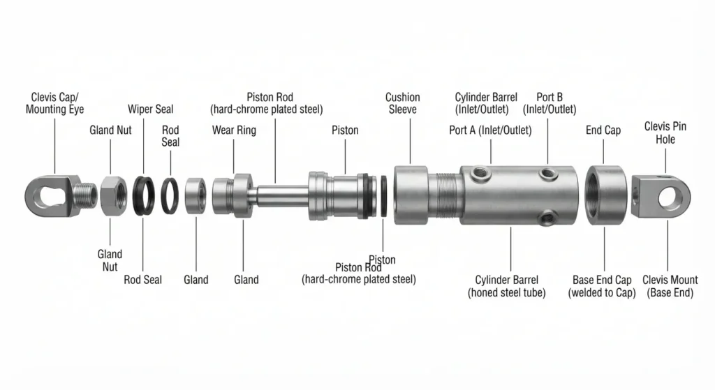
A typical piston-type hydraulic cylinder consists of a cylinder barrel, a piston, a piston rod, end caps, sealing and guiding components, oil ports and mounting fittings. To begin with, you can think of it this way: the cylinder barrel provides the pressure-bearing chamber, the piston moves within it, and the piston rod transmits the thrust or pulling force to the equipment. The end caps enclose the working chamber, the seals prevent hydraulic fluid leakage, and the guide components help keep the moving parts centred. Some models also feature cushioning and venting mechanisms.
This GY Hydraulic guide focuses primarily on the common single-rod double-acting cylinder: it has a piston rod extending from only one end, and both extension and retraction are driven by hydraulic fluid. The component configurations of single-acting cylinders, double-rod cylinders and telescopic cylinders will differ. When familiarising yourself with components, it is more practical to first observe where they are located and what function they perform, then cross-reference their names on the drawings, rather than simply memorising their English terms.
Table of Contents
How Hydraulic Cylinder Parts Work Together?
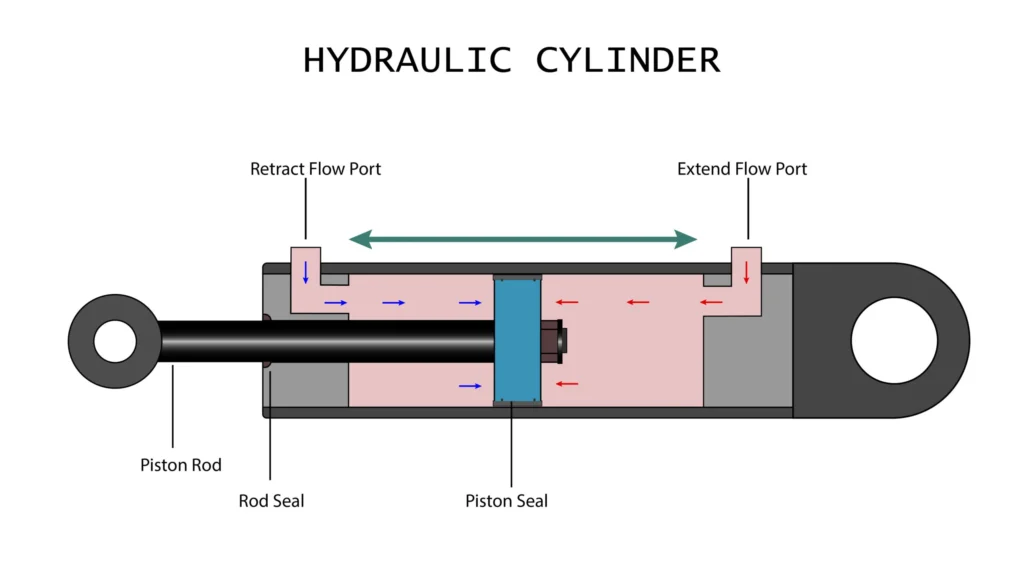
A hydraulic cylinder converts the energy in the hydraulic fluid into linear thrust or pull motion. In a typical double-acting cylinder, a control valve directs pressurised fluid to one side of the piston, whilst fluid on the other side flows out through the circuit; this causes the piston to drive the piston rod. The side of the piston without the rod is usually referred to as the rodless chamber, whilst the side with the rod is called the rod chamber. By switching the direction of fluid supply, the direction of motion can be altered.
Seals help maintain the required pressure differential between the two sides, whilst guide components minimise movement deviation; the cylinder head and base, together with the cylinder barrel, form a pressure-bearing housing. The force is then transmitted to the equipment via mounting fittings at the piston rod end and the cylinder body end. For example, when a working arm is raised, the hydraulic fluid provides the driving force, whilst the pin and mounting bracket are responsible for transmitting the thrust to the working arm; the absence of any one of these components would prevent normal operation.
When examining an assembly drawing, you can trace the path of ‘where the oil enters, which component it drives, and where the force is ultimately transmitted’ to identify the relevant parts. It is also important to note that, under the same oil pressure, the effective pressure area of a standard single-rod cylinder differs between extension and retraction; consequently, the thrust and tensile force are usually different. The effective pressure area is the area over which the oil pressure actually generates thrust; therefore, the output capacity cannot be determined solely by the external dimensions of the cylinder barrel.
Cylinder Barrel or Tube
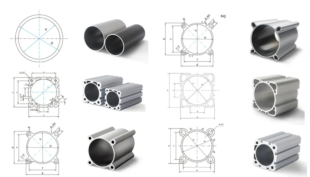
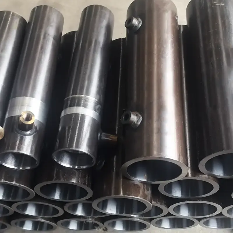
The cylinder barrel is the pressure-bearing body of a hydraulic cylinder, and its inner wall also serves as the working surface for the piston seals and guide components. The cylinder bore refers to the working inner diameter of the cylinder barrel, not the outer diameter. It affects the area over which the piston is subjected to pressure, whilst the cylinder barrel’s material, wall thickness, end connections and overall design collectively influence its pressure-bearing capacity. It cannot be directly substituted with an ordinary steel pipe that is ‘roughly the same diameter and has sufficiently thick walls’.
The inner surface of the cylinder barrel must meet specified requirements for dimensions, shape and surface quality. Common machining methods include honing, which involves precision grinding of the bore to improve surface and geometric accuracy. A shiny inner surface does not necessarily mean it is suitable for sealing; scratches, pitting caused by corrosion or localised deformation may all affect the service life of the seals. Manufacturers will specify bore machining requirements for specific products, rather than simply stating a pipe size.
If you wish to request a quotation or replace a cylinder barrel, you should provide the internal diameter, external diameter, length, material and end connection drawings, and verify the internal bore tolerances and surface requirements. Tolerances refer to the permissible range of deviation from the target value. For example, two cylinder barrels with the same bore diameter but different end threads are not necessarily interchangeable.
Piston and Piston Seals
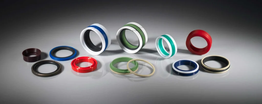
The piston is the load-bearing component that moves within the cylinder barrel in conjunction with the piston rod, whilst the piston seal is fitted into the corresponding seal groove to prevent hydraulic fluid from flowing from one side of the piston to the other. Only when these two components work together can the pressure differential between the two chambers be maintained when required. Some designs utilise an integrated bidirectional seal, whilst others employ a combination seal or a separate arrangement; therefore, the replacement type cannot be determined solely by the appearance of the old component.
You may regard the piston as a component that receives hydraulic pressure and transmits force; the seal must not be treated as part of the piston body itself. There may also be threads, locking devices or internal static seals between the piston and the rod; static seals are used at joints where there is no relative movement. Connection methods vary between different models, and some assemblies are not designed to be disassembled for on-site repair.
When ordering pistons or piston repair kits, verify the cylinder bore, rod connection dimensions, seal groove widths and guide configurations. For example, two pistons with the same cylinder bore cannot automatically be assumed to share the same set of seals if their seal groove widths differ. Furthermore, if the equipment is found to be slowly slipping, one should not immediately conclude that the piston seals are damaged, as circuit issues such as internal valve leakage may equally cause positional changes.
Piston Rod and Rod Surface
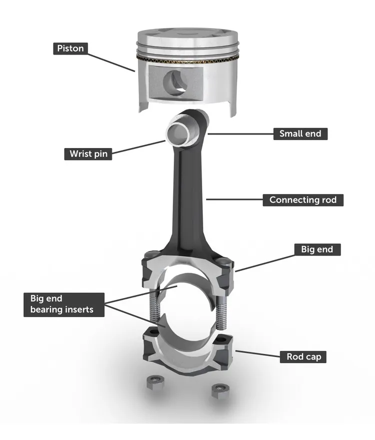
The piston rod connects the piston to the external load, transmitting the force generated within the cylinder to the equipment. It must withstand both tensile and compressive forces, whilst also providing a working surface for the rod-end seals. Common steel piston rods are subject to surface treatments such as chrome plating; however, the specific material and coating should be selected based on the corrosive environment, wear, seal fit and manufacturer’s requirements—it is not simply a matter of ‘the thicker the coating, the better’.
Once the equipment has been safely shut down and the relevant components have been securely supported, you may inspect the visible surface of the rod for longitudinal scratches, rust spots, flaking of the coating or impact damage. For example, pits on the rod surface that repeatedly pass over the sealing lip may cause a new seal to fail prematurely; the sealing lip is the edge that contacts the rod surface and controls the flow of hydraulic fluid. Therefore, in the event of oil leakage at the rod end, both the seal and the rod surface should be inspected simultaneously.
When selecting a replacement rod, verify the rod diameter, length, end connections, straightness and surface finish requirements. For rods with long strokes or operating under high pressure, it is also necessary to verify their resistance to bending buckling—that is, whether they are likely to bend when under pressure. Do not simply fit a thinner rod just because it has the same mounting thread, nor should you use pipe pliers to grip the working surface where the seal is located.
Cylinder Head, Gland, and Rod Guide
All three terms relate to the rod end, but do not necessarily refer to the same component. You should consult the sectional drawing for that model to confirm whether they are separate components or integrated into a single assembly.
① Understand the Different Functions
The cylinder head is typically located at the end from which the piston rod extends; it seals the cylinder bore and provides structural support for the rod end assembly. It may feature working oil ports, sealing grooves or cushioning structures. The guide sleeve or gland typically houses the rod seal, dust seal and associated guide components; in some designs, it can be removed from the cylinder head as a separate component.
The rod guide is responsible for supporting and guiding the rod’s movement; it may consist of a metal bushing, a non-metallic guide ring, or a guide surface integrated into the rod end assembly. The term ‘bearing’ in this context does not necessarily refer to a ball bearing; parts that provide support via a sliding fit are common here.
For example, in some Parker hydraulic cylinders, the ‘Head’ and ‘Gland’ are listed as separate parts, with the Gland potentially incorporating both sealing and guiding structures. However, other manufacturers may integrate similar functions into a single unit and use different terminology. When requesting a quotation, specifying the drawing number and assembly location is more reliable than simply referring to a ‘Gland’.
② Check the Assembly Before Ordering
If you notice oil leakage at the rod end, do not immediately assume that the entire cylinder head needs replacing. A maintenance technician should inspect the seals, the rod surface and the guide clearance. Guide clearance refers to the permissible fit between the rod and the guide component; excessive clearance or misalignment during installation may cause uneven stress on the seals. Simply replacing the seals may not resolve this issue.
When preparing replacement part specifications, focus on verifying the following:
- Fastening method: Whether it is threaded, bolted, secured with a retaining ring, or uses another retaining mechanism; do not rely solely on appearance to determine the disassembly method.
- Scope of supply: Whether you are purchasing an empty guide sleeve, an assembly including a sleeve, or a complete unit with the seal already fitted.
- Fitting specifications: Check that the rod diameter, connection dimensions to the cylinder barrel or cylinder head, and seal groove dimensions match those specified in the drawing version.
Do not attempt to eliminate guide clearance by over-tightening the rod-end assembly. Tightening the connection and restoring a worn fit are two distinct procedures; follow the maintenance procedures specified for that particular model.
Base Cap and End Cap
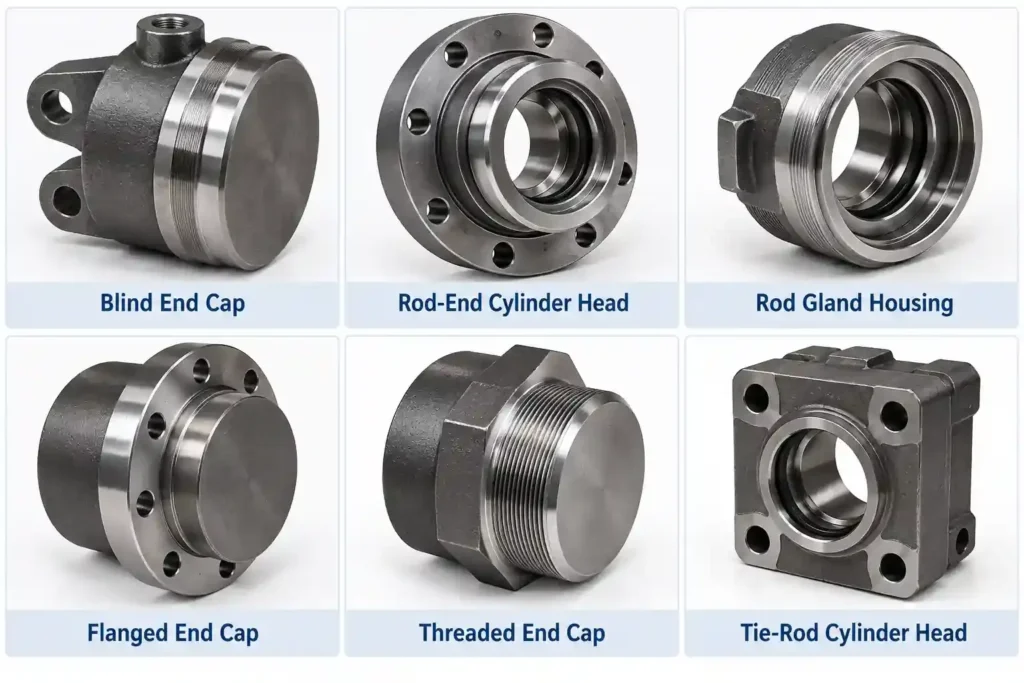
In a standard single-rod cylinder, the base cap is located at the end from which the piston rod does not extend; it seals the cylinder barrel and bears the load generated by the hydraulic pressure. It may feature oil ports, buffering devices or mounting lugs. ‘End cap’ is a broader term; some drawings use it to refer to the base cap, whilst other documentation uses it generically to denote any end-sealing component. Therefore, when purchasing, it is advisable to specify ‘rod end’ or ‘non-rod end’.
The base cap may be connected to the cylinder barrel by welding, tie-rod clamping or other design methods. A base cap welded to the cylinder barrel is not usually the part that needs to be cut away during routine disassembly and seal replacement. For example, a welded cylinder may allow the piston assembly to be removed from the rod end for maintenance without the need to cut away the base cap.
When identifying parts, you should examine the cylinder base joint, oil ports and mounting structure, rather than simply looking at which end is facing up or down. If cracks, deformation or abnormal welds appear in pressure-bearing areas, a professional assessment must be carried out; this should not be addressed by simply applying sealant or retightening external fasteners.
Rod Seals, Wipers, Wear Rings, and Static Seals
These components often appear together in repair kits, but they serve different purposes. If you first distinguish between these four functions—‘retaining oil, blocking contaminants, providing guidance, and sealing fixed joints’—you are unlikely to choose the wrong part.
a. Match Each Part to Its Job
| Observation | Conclusions that can be supported | What cannot yet be directly proven | What should be verified next |
|---|---|---|---|
| Drift observed in the original circuit | The ability to maintain position under specified operating conditions requires assessment | Does not, on its own, prove damage to the piston seal | Model-specific limits, external leakage, temperature variations and valve circuits |
| No further drift after isolation | Altered hydraulic circuit boundaries have affected movement | Does not prove that there is no cross-leakage between the piston’s two sides | Pressure in both chambers, enclosed volume and independent leakage tests |
| Pressure decreases over time | Changes in pressure conditions within the test range | Cannot pinpoint the cylinder or valve based on a single gauge reading | Temperature, position, isolation components and external connections |
| Pressure differential between chambers narrows | Pressure redistribution may be occurring | Cannot directly quantify bypass flow whilst the piston is moving or during temperature changes | Check for displacement, test valve leakage and inter-chamber flow |
| Localised thermal or acoustic anomalies | Areas of concern warranting further investigation | Cannot prove that a specific seal has failed | Normal throttling, mechanical vibration, heat conduction and verification measurements |
| Excessive cross-chamber flow measured during a qualified specialised test | Leakage paths within the cylinder require repair | Flow alone cannot distinguish between seal damage and cylinder barrel damage | Structural diagrams and disassembly inspection results |
Both rod seals and piston seals are dynamic seals, meaning there is relative movement between the sealing contact surfaces. Dust seals primarily address external contaminants, but some double-lip designs also help control the oil film on the rod surface; therefore, they must be matched with the rod seal according to the design. Wear rings, on the other hand, help to keep the piston and rod centred; they must not be treated as seals and replaced simply because they ‘also resemble a ring’.
For example, if a dust seal is damaged, grains of sand may enter via the rod, causing further wear to the rod surface and internal seals; if a guide ring is severely worn, a new rod seal may also suffer from uneven wear very quickly. You should inspect all associated components and must not simply replace the single seal located near the visible oil leak.
b. Select Replacements Based on More Than Just Diameter
Confirm Dimensions and Profiles
Prioritise confirming the repair kit using the hydraulic cylinder model, serial number and parts list. Where a complete part number is unavailable, provide the seal groove dimensions, seal cross-section and mounting position for the supplier to verify. The seal cross-section refers to the shape visible when the seal is cut radially; this affects both installation and operational behaviour.
For example, two rod seals with the same internal diameter may differ in height, external diameter or lip configuration; they must not be purchased based on internal diameter alone. Old seals may have become worn, deformed or swollen, and are therefore unsuitable as the sole basis for accurate sizing. O-rings are annular seals with a circular cross-section; when selecting them, dimensions, materials and fit requirements must also be verified.
Match Fluid and Operating Conditions
Provide the supplier with the actual fluid grade, temperature range, operating pressure and movement speed, and then verify the seal material and design. For example, if a piece of equipment has switched to a water-glycol fire-resistant fluid, one cannot assume that the seals originally intended for mineral hydraulic oil will still be suitable. Material compatibility refers to whether contact between the fluid and the seal will cause unacceptable swelling, hardening or changes in performance.
Before installation, inspect the seal groove and surrounding edges, protect threads and orifices, and use lubricants and tools authorised by the manufacturer. Assembly issues caused by sharp edges cutting into new seals can be minimised through proper preparation. Seal repair kits may not necessarily include guide rings, bushings and all retaining components; therefore, the list should be checked item by item when ordering.
Hydraulic Ports, Cushions, and Bleed Features
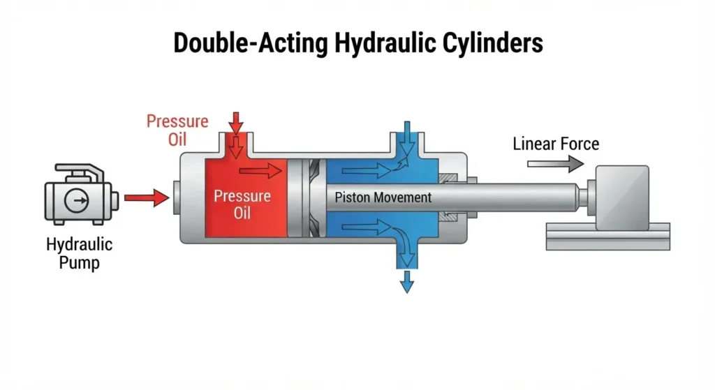
Hydraulic ports are the interfaces through which fluid enters and exits the working chamber. Common double-acting cylinders have oil circuits leading to both working chambers, but the external ports are not necessarily located at opposite ends of the cylinder barrel; they may also be centrally arranged via internal passages. When connecting pipes or selecting fittings, you should check the hydraulic circuit diagram, thread type, sealing method and required flow rate; you must not assume a fitting is compatible simply because it ‘screws in’, nor should you assume that all fittings are sealed by wrapping with PTFE tape.
Buffering devices are used to slow down movement as the cylinder approaches the end of its stroke; they typically achieve deceleration by restricting oil flow. For example, when a heavy mechanism approaches the end of its stroke at high speed, appropriate buffering can reduce impact; however, if the equipment only operates in the middle section of its stroke, end-of-stroke buffering may not even enter the working area. The need for buffering must be assessed in conjunction with the moving mass, speed and available deceleration distance. It cannot replace a load-holding valve to maintain the load, nor should it be treated as a full-stroke speed control device.
Bleeding mechanisms are used to help remove air trapped within the cylinder; they may utilise dedicated bleed ports or other designs, and not every cylinder has the same bleed screw. You should first consult the drawings to distinguish between the bleed port, the buffer adjustment mechanism and the working oil port, and then proceed in accordance with the model specifications; do not arbitrarily unscrew a small screw in an attempt to bleed the system, nor should you loosen fittings whilst the system is under pressure.
Mounts, Clevises, Pins, and Bearings
Mounting accessories transmit the thrust and pull forces of the hydraulic cylinder to the equipment and determine whether it can swing in unison with the mechanism. Common types include flanges, foot mounts, lugs, fork lugs and pivot pins. Flanges and foot mounts are typically used for fixed installations; fork lugs form a hinged connection via a pin; pivot pins are shaft-like mounting points on both sides of the cylinder body used to support swinging motion. The specific choice depends on the direction of the load’s movement and the overall structure of the machine.
A pin connects two hinged components, whilst a bushing or spherical plain bearing helps to bear contact loads and allows for specified movement. Spherical plain bearings feature a spherical sliding fit that accommodates angular deviations within the design range but cannot compensate for severe misalignment. For example, when a working arm moves, the hydraulic cylinder needs to swing about the pin; if, after installation, it encounters interference from adjacent structures, the rod end and internal guide components may be subjected to additional lateral forces.
When selecting a replacement cylinder or mounting component, you should verify the pin bore diameter, lug width, mounting centre distance, swing range and load-bearing requirements. The mounting centre distance is the distance between the corresponding mounting reference points and is not equivalent to the overall length of the cylinder body. Lubrication must also be carried out in accordance with specific bearing requirements; it cannot be assumed that all articulated joints require the same lubrication method. Where pins, bores or bushings have worn, gaps should not be masked by arbitrarily adding shims.
How Parts Differ in Tie-Rod, Welded, and Telescopic Cylinders
The terms ‘tie-rod type’ and ‘welded type’ primarily describe the method of connecting the pressure-bearing casing, whilst ‘telescopic type’ primarily describes the multi-stage movement mechanism. These classifications are not entirely mutually exclusive; a telescopic cylinder may also feature welded joints. You should verify separately how the casing is connected and how the movement stages are arranged; you cannot infer the characteristics of all components based solely on a single category name.
① Tie-Rod Cylinders
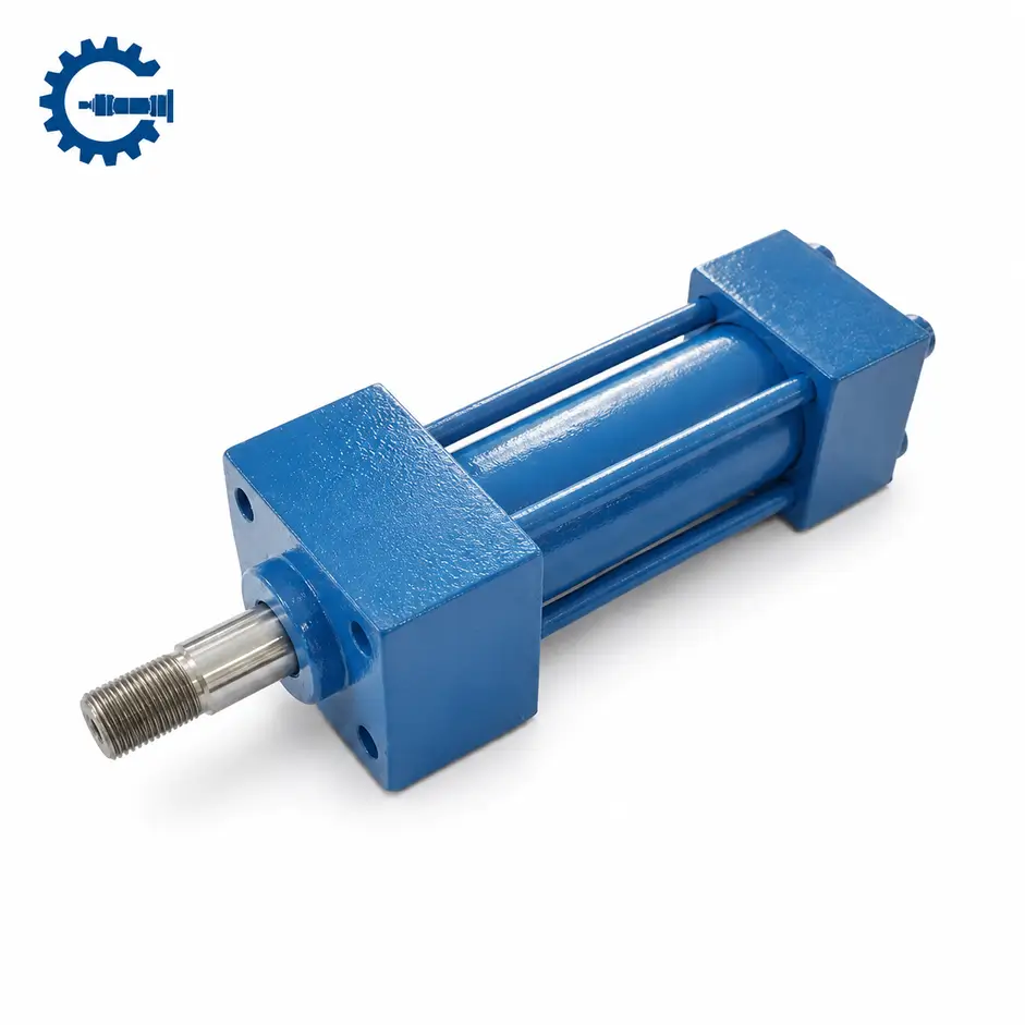
Tie-rod hydraulic cylinders connect the cylinder head, cylinder barrel and cylinder base via long rods arranged along the exterior of the cylinder body. These long rods are referred to as tie-rods and are distinct from the piston rod that moves reciprocally within the cylinder. The external tie-rods, nuts and end static seals are the components that require attention when identifying and maintaining this type of structure.
For example, when procuring replacement tie-rods, in addition to length and thread specifications, one must also verify the material, strength requirements and fastening specifications. They must not be substituted with standard bolts that merely appear similar, nor should end leaks be addressed by simply tightening a single tie-rod. When a complete cylinder needs to be replaced, the installation dimensions and configuration must be checked; one must not assume that all tie-rod cylinders are interchangeable.
② Welded Cylinders
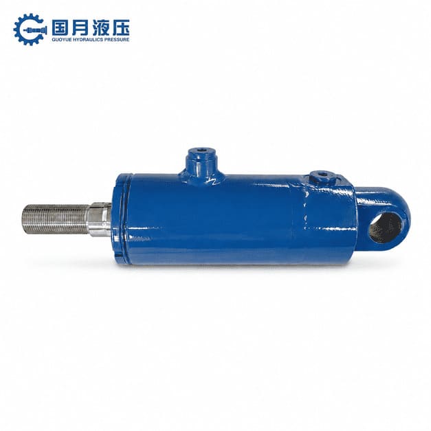
Welded hydraulic cylinders typically utilise welded joints to connect the cylinder barrel to the cylinder base or other pressure-bearing components; they do not feature external tie rods for clamping both ends. The rod ends may still utilise removable threaded guide sleeves, bolted end caps or retaining ring assemblies. Therefore, the term ‘welded’ does not automatically imply that the cylinder barrel must be cut open during repair.
If you need to determine whether the seals can be replaced, first check the rod-end retention method and the maintenance documentation. For example, a particular welded cylinder from Eagle Hydraulic explicitly uses a threaded gland, indicating that a welded housing and a removable rod end can coexist. This structural example cannot be directly applied as a basis for disassembly and assembly of other models.
③ Telescopic Cylinders
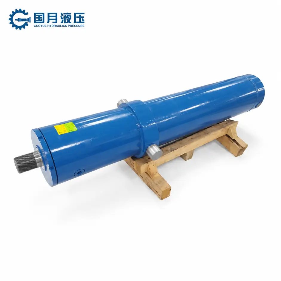
Telescopic hydraulic cylinders utilise multiple stages of nested moving tubes, with each extendable sleeve forming a corresponding stage of movement; the specific number of stages and their designations should be confirmed against the manufacturer’s drawings. They can provide a long stroke with a short retracted length and are therefore frequently used in lifting mechanisms where installation space is limited. Each stage may have its own seals, guides and limiters, and the outer surface of one stage may also serve as the working surface for the adjacent seal. Limiters are used to restrict the permissible stroke of a movement stage or to prevent the cylinder from extending beyond its limits.
For example, if the outer surface of a stage in a tipper lorry’s lifting cylinder is damaged, you should first confirm which stage it is and where the damage is located, before checking the parts for that specific stage. Simply providing the outer diameter of the entire cylinder or specifying it as a ‘multi-stage cylinder’ is usually insufficient to order the correct seals. Double-acting telescopic cylinders also require corresponding retraction oil circuits and seal configurations; parts lists for single-acting telescopic cylinders cannot be directly applied.
When checking parts or requesting custom configurations with GY Hydraulic, you should have the nameplate, assembly drawing, required part numbers, installation dimensions, hydraulic fluid grade and operating conditions to hand. If drawings are unavailable, please first provide clear photographs of the overall appearance and connection points, specifying which dimensions remain unconfirmed, to avoid selecting the wrong parts based solely on similar external appearances.
FAQs
What are the two ends of a hydraulic cylinder called?
Standard single-rod cylinders are typically divided into the rod end (also commonly referred to as the head end) and the non-rod end (cap end, also known as the blind end). The rod end is the side from which the piston rod protrudes. Double-rod cylinders have rods at both ends, so the identification method of ‘one end with a rod, the other end sealed’ cannot be applied directly. When requesting a quotation, it is best to include photographs or drawings to avoid misunderstandings arising from differences in the terminology used by different suppliers for end caps.
What is the difference between a gland and a cylinder head?
The ‘head’ is usually the structural sealing component at the rod end, whilst the ‘gland’ typically houses the rod seal and associated guide components. In some designs, these are separate parts; in others, they form a single assembly. When ordering, you should confirm the part number and scope of supply, rather than simply stating ‘I need a guide sleeve’; otherwise, you may receive an empty part that does not include the sleeve or seal.
What keeps hydraulic oil from leaking around the rod?
This is primarily achieved by the piston rod seal, working in conjunction with a properly machined rod surface, correct installation and the relevant static seals. Dust seals are mainly used to block external contaminants and cannot replace the main rod seal. If there is oil leakage at the rod end, you should inspect both the rod surface and the guidance condition; do not assume that the outer dust seal is the only damaged component simply because it is visible.
What supports the piston rod inside the cylinder?
The piston rod is typically supported by a guide bushing or guide ring at the rod end, whilst the guide structure on the piston side also helps to maintain the alignment of the entire moving assembly. Refer to the sectional drawing for the specific configuration. If you notice lateral play or uneven wear on the rod, you should inspect the guide fit and installation condition; replacing the seal with a tighter one is not a suitable substitute for restoring proper support.
Why are wear rings used in hydraulic cylinders?
Wear rings help guide the piston or piston rod and reduce direct metal-to-metal contact between moving parts. They perform a guiding function within the limits permitted by the design; they cannot allow a standard hydraulic cylinder to withstand lateral forces indefinitely. When selecting wear rings, verify the installation position, dimensions, material and load capacity; do not purchase them based solely on colour or appearance.
What is the purpose of a cylinder cushion?
Cushioning is used to reduce impact as the stroke nears its end. Its effectiveness depends on whether the actual movement enters the cushioning zone, and whether the load, speed and configuration are appropriate. If you only stop midway through the stroke, end cushioning generally cannot replace external deceleration control; when selecting a model, you should specify in which direction and at what position deceleration is required.
Are single-acting and double-acting cylinder parts different?
They may differ. Double-acting cylinders are driven by hydraulic pressure in both directions, whilst single-acting cylinders are typically driven by hydraulic pressure in one direction, with the return stroke relying on the load, gravity or a spring. Single-acting does not necessarily imply the presence of a return spring, nor does it necessarily mean there is no piston; the internal configuration of a plunger-type single-acting cylinder differs from that of a piston-type cylinder. You should first confirm the structure and return mechanism before selecting parts.
Which hydraulic cylinder parts commonly wear out first?
Seals, dust seals, guide components, as well as pins and bushings at mounting points, are all common areas to check for wear; however, there is no fixed order of priority applicable to all operating conditions. In dusty environments, particular attention should be paid to dust seals and rod surfaces, whilst at joints subject to frequent oscillation, focus should be on pins and bearings. Carrying out routine inspections in accordance with equipment requirements, and making judgements based on oil stains, abnormal clearances and scuff marks, is more reliable than making assumptions based solely on the length of service.
Choosing a Trusted Hydraulic Cylinder Manufacturer
From standard hydraulic cylinders to custom solutions, we help you improve equipment performance, delivery reliability, and batch consistency
Explore Rivmate Cases

Hey There, I'm Melody!
We are a hydraulic cylinder manufacturer. For over 20 years, we have focused on producing reliable hydraulic cylinders. Need a hydraulic cylinder solution? Feel free to contact us.