Home / Hydraulic Cylinder Leakage Causes and Troubleshooting Guide
Hydraulic Cylinder Leakage Causes and Troubleshooting Guide
- Author: GY Hydraulic
- 20+ Years of Manufacturing
The main causes of hydraulic cylinder leaks include seal wear or damage during installation, piston rod defects, hydraulic fluid contamination, abnormal pressure and temperature, misalignment during installation, and damage to the cylinder barrel or port connections. To resolve oil leaks, first locate the leak path, then investigate the conditions causing the damage. If rod surface scratches, excessive guide clearance or abnormal pressure are left unaddressed, new seals will still face the same issues.
This GY Hydraulic guide follows the sequence ‘Identify the type – Check the cause – Locate the fault – Address recurrence – Preventative maintenance’ to help you decide what to check next, which situations require testing, and when to extend the scope of repairs. The explanation of internal oil leakage is primarily aimed at common double-acting hydraulic cylinders; for single-acting cylinders, multi-stage telescopic cylinders and special designs, the corresponding repair procedures should be used.
Table of Contents
External vs Internal Hydraulic Cylinder Leakage
External leakage occurs when hydraulic fluid flows outside the hydraulic cylinder or connection points; internal leakage occurs when hydraulic fluid passes through seals internally, flowing from one area to another. The piston rod is a metal rod that extends and retracts; the rod seal prevents hydraulic fluid from flowing out from the rod outlet. Double-acting hydraulic cylinders rely on the alternating supply of fluid to both sides of the piston to achieve extension and retraction, whilst the piston seals prevent cross-flow of fluid between the two sides.
| Leakage Type | Direction of Fluid Flow | What You Might Observe | Priority Inspection Locations |
|---|---|---|---|
| External leakage | Flows out from the hydraulic cylinder or connection points | Fresh oil stains, oil pooling, oil droplets or streaks | Rod end, end cap connections, oil ports, fittings and adjacent hoses |
| Internal leakage | Common in double-acting cylinders, where fluid bypasses the piston and flows into the low-pressure chamber | External oil traces may not be visible; further diagnosis is required if the cylinder slows under load or exhibits abnormal thrust or position holding | Piston seals, cylinder bore; also check the control valve and load-holding circuit |
Slow load drop-off alone cannot confirm damage to the piston seals. Internal leakage in the control valve can also cause positional changes. External leakage must also be traced to its source: oil leaking from an upper fitting may run down the cylinder body to the underside of the end cap; the lowest point where oil is dripping may not necessarily be the point of origin.
A thin oil film on the rod surface must be distinguished from obvious leakage. Moving seals require oil film lubrication; to determine this, check whether oil continues to accumulate or form droplets after cleaning, and verify the acceptance criteria for that specific model. Once the type of issue has been identified, proceed to inspect according to the six categories of causes listed below, to avoid dismantling the cylinder and replacing seals simply upon seeing oil traces.

① Worn, Damaged, or Incorrectly Installed Seals
Seals that are worn, nicked, twisted or pinched will all compromise their contact with the metal surface. The seal lip is the edge that contacts the piston rod or cylinder barrel and performs the primary sealing function; failure of the rod seal will cause external leakage at the rod end, whilst failure of the piston seal will increase oil carry-over between the two sides.
When dismantling and inspecting, first record the nature of the damage and the installation orientation. Localised cuts should be traced back to threads, burrs and sharp edges along the assembly path; unilateral wear requires checking the guidance and alignment; if the edge is thinned or torn, verify the pressure, material and component clearances. Extrusion damage occurs when the seal material is forced into the metal gap under pressure and is subsequently destroyed. Photographs can provide clues, but a definitive diagnosis requires dimensional measurements and operating condition records.
When selecting replacement parts, verify the cross-section, groove dimensions, material and pressure direction against the hydraulic cylinder model, assembly drawing and part number. Grooves are machined channels that house and support the seals. If the old part is worn or has expanded, measuring only its diameter may result in selecting the wrong specification. For example, even if two seals have the same inner and outer diameters, they cannot be directly interchanged if their cross-sectional height and material differ.
Before installation, remove any contaminants and burrs, cover the threads that will be engaged with protective caps, and use the specified tools and compatible lubricants. The opening of a common single-direction U-shaped seal typically faces the pressure side; for composite seals and cushioning structures, refer to the assembly drawing for confirmation. Each component must be reinstalled according to its part number and the assembly drawing; replacement based solely on similar appearance is not permitted.
② Scored, Bent, Corroded, or Poorly Finished Piston Rods
When oil leaks from the rod outlet, the rod surface through which the seal passes must be inspected. Scores and grooves can compromise seal contact, whilst raised edges may wear down or cut into the lip; pitting caused by corrosion—that is, small localised pits—remains even after surface rust has been removed. For example, a longitudinal groove running through the seal’s working area requires measurement of the extent of the damage and investigation into the source of abrasive particles or metal contact.
A bent piston rod subjects the guides and seals to uneven forces. Jamming when extended, one-sided wear of the guide components, or abnormal scuffing on the rod surface should all trigger an inspection of straightness and fit. Maintenance personnel must carry out measurements in accordance with the drawings; visual inspection alone is not sufficient. Once permanent bending has been confirmed, the component must be submitted to the manufacturer or a qualified repair provider for assessment; it must not be hammered straight or used immediately after heating.
A rod surface that appears smooth does not necessarily mean it is suitable for sealing. Surface roughness describes microscopic peaks and valleys, which affect wear and the retention of the oil film; relying solely on the average roughness index Ra does not fully reflect localised defects. Whether minor damage can be polished out depends on whether the rod diameter, coating and surface requirements can be met after treatment. Deep grooves, obvious pitting or coating flaking should be assessed for professional repair or replacement; simply sanding the surface until it ‘feels smooth’ does not constitute a repair.
③ Contaminated Fluid and Failed Rod Wipers
Hard particles entering the seal contact area will wear down the seal and scratch the metal surface. Contaminants originate not only from external sand and dust, but also from assembly residues, maintenance procedures and internal system wear. The dust seal, located near the rod outlet, scrapes away deposits as the piston rod retracts; notches, cracks, dislocation or poor seating will all reduce the effectiveness of this barrier.
For example, if damage to the dust seal and scratches on the rod surface are observed simultaneously in a muddy environment, the route by which external contaminants entered should be investigated. The presence of dust on the outer surface of the dust seal does not necessarily indicate failure, as this is precisely where contaminants are intended to be blocked. You should assess its integrity, installation status and rod surface damage in conjunction. When selecting a dust seal, inform the supplier of the dust, sludge, debris or flushing environment, whilst also verifying the temperature, speed and fit requirements with the rod seal.
The suitability of the hydraulic fluid must be determined by testing for particulates and moisture following prescribed sampling procedures; it cannot be judged solely by its clarity. The cleanliness grade reflects the level of particulate contamination; filters should be selected according to the target grade, filtration efficiency, flow rate and viscosity required by the equipment. Finer filter elements may not necessarily be suitable for existing systems, nor can a damaged dust seal be compensated for by increasing filtration.
Water contamination requires separate treatment. Standard particulate filtration cannot replace dehydration, and some specialised water-absorbing filter media can only treat free water—that is, water not dissolved in the oil. For systems originally designed to use water-containing media such as water-glycol, management must follow the specified requirements for the fluid and materials; the criteria for mineral oil systems cannot be applied indiscriminately.
④ Overpressure, Pressure Spikes, and Excessive Temperature
Overpressure occurs when the actual pressure exceeds the permissible value for a component under specified operating conditions; pressure spikes are sudden, transient increases in pressure. Excessive pressure increases the risk of seal extrusion, whilst high temperatures can cause certain materials to soften or accelerate ageing. To determine whether a seal is suitable, one must consider pressure, temperature, speed and clearance simultaneously; the highest values listed in technical data sheets must not be combined directly.
Readings at the pump outlet do not represent the full operating conditions on both sides of the hydraulic cylinder. For example, excessive restriction of return flow in the rod chamber during extension can cause localised pressure build-up under specific load and area conditions. The rod chamber is the side containing the piston rod, where the effective pressure-receiving area is smaller than on the opposite side. Technical personnel should measure the pressure in both chambers in conjunction with the circuit, checking return flow restrictions and pressure protection, rather than merely adjusting the power unit settings.
If leakage is concentrated during rapid directional changes or after an emergency stop, record the corresponding pressure changes for these operations. Standard mechanical pressure gauges, limited by their response time and damping, may fail to detect transient peaks; test instruments must be selected to match the required response speed, sampling capability, measurement range and pressure rating. Fitting a buffer to a pressure gauge merely protects the instrument; it does not confirm that internal cylinder shock has been eliminated.
When oil seepage occurs after the machine has warmed up, simultaneously check the oil temperature, oil viscosity, clearances and cooling efficiency. Viscosity refers to the thickness of the oil as it flows; it is affected by rising temperatures. Leaks and friction also generate heat; therefore, the progression of these changes must be recorded, rather than simply replacing seals with ‘high-temperature-resistant’ alternatives. Oil in sealed chambers may also experience pressure build-up due to heating; thermal expansion-induced pressure relief serves a different purpose to load shock protection and must be assessed separately.
⑤ Side Loading, Misalignment and Mounting Problems
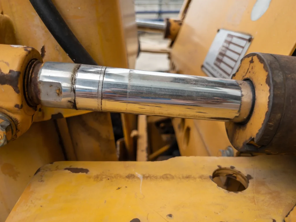
Side loading refers to forces acting in a direction deviating from the piston rod’s axis; misalignment refers to a positional or angular deviation between the cylinder axis and the direction of load movement. These cause the guide components to bear off-centre loads, whilst clearance and wear further compromise the seals. Guide components help the piston and rod maintain their correct position; their load-bearing capacity depends on their specific design and they cannot substitute for load guidance that should be provided by external mechanisms.
For example, when a hydraulic cylinder drives a slide block, a jammed guide rail will transmit lateral forces back to the rod end. In such cases, the guide rails, connections and mounting arrangements should be rectified; simply replacing the seals with more wear-resistant ones will not eliminate the off-centre loading. Inspections must cover the entire stroke, particularly near the fully extended position; it is not sufficient to merely confirm that the connection operates smoothly when retracted.
The mounting configuration must match the motion trajectory. Fixed mounting is used for corresponding linear motion; articulated mounting, such as with fork brackets or trunnions, allows the cylinder body to swing with the mechanism. For flat fork bracket structures, check whether the axes of the pins at both ends are parallel, whether there is interference at the full swing angle, and whether the pins or bushings are seized or excessively worn. Bushings are tubular components used at joints to provide support and reduce wear.
Spherical connections can only compensate for angular deviations within the design range; they cannot correct arbitrary misalignments. During long-stroke compression, it is also necessary to verify the rod diameter, supports and the risk of buckling—that is, the risk of a slender rod buckling and bending due to compression. If sticking is detected, first check the mechanical connections; do not increase the pressure to force the cylinder through.
⑥ Damaged Tubes, Pistons, Ports and Fittings
Scratches, corrosion or deformation on the inner wall of the cylinder barrel will affect the sealing contact of the piston; damage to the edges and walls of the piston grooves will compromise the seal support. Upon confirming internal leakage, the inner diameter, shape and piston fit of the cylinder barrel should be inspected and measured; simply replacing the seals is not sufficient. Honing is a machining method for refining the inner bore, which removes material; it is only applicable if permitted for that model and if the dimensions and pressure-bearing requirements are still met after machining.
In the event of oil leakage from ports and fittings, first identify the actual sealing points. For example, in the case of an O-ring face seal, the seal prevents leakage by pressing against the sealing surface, whilst the thread is responsible for the connection; scratches on the sealing surface or the absence of the O-ring cannot be rectified by wrapping with Teflon tape. Although NPT and BSPT are both tapered pipe threads, they must not be used interchangeably. When replacing fittings, verify the thread type, seal type, material and pressure rating simultaneously, and assemble in accordance with the corresponding torque or specified tightening method.
If cracks, bulging or obvious deformation appear in pressure-bearing areas, cease use immediately and assess the structural condition. Do not continue tightening or reuse the component directly after on-site welding repairs. Damage limited to the joint seal alone may be addressed locally; however, if the dimensions of the cylinder barrel, piston or guide exceed the specified limits, the scope of repair must be expanded. Have the manufacturer or a qualified repair provider confirm whether the parts can be restored to the required specifications before deciding whether to recondition or replace them.
How to Locate and Diagnose the Source of a Leak
The troubleshooting sequence is as follows: record the symptoms, safely relieve pressure, clean the area and trace any new oil stains, then use controlled measurements to distinguish between internal cylinder leaks and circuit faults. Completing external localisation first can minimise the need for unnecessary cylinder disassembly; where internal leaks are suspected, a specialist should then establish test conditions appropriate to the cylinder type.
1. Record the Symptoms Before Cleaning
Without coming into contact with the operating equipment, photograph the original oil stains and record whether the leak occurs during extension or retraction, whilst moving or at rest, when the machine is cold or hot, under no-load or under load, as well as details of the most recent maintenance. For example, if oil seepage occurs immediately after replacing a fitting, first re-check the fitting specifications and assembly; if it only occurs under heavy load whilst the machine is hot, prioritise recording the pressure and oil temperature at that time.
The following format may be used: Model/Action and Load/Oil Temperature/Initial Leak Location/Duration of Observation/Photograph Number. Pressure, displacement and test flow rate should be supplemented by qualified personnel. Leave any missing data blank; do not substitute measured values with estimates.

2. Ensure the Equipment is Safe, Then Clean the Area
Before cleaning, taking close-range measurements or dismantling, shut down the equipment in accordance with operating procedures, isolate the power supply, securely support the load, and release any residual pressure in the relevant circuits. Residual pressure is the pressure still trapped within the system after the pump has been stopped; therefore, switching off the motor does not equate to the system being depressurised. Pressure checks and release must be carried out using prescribed procedures and equipment; do not rely on loosening fittings to confirm that pressure has been released.
Use compatible, clean and lint-free materials to clean the rod outlet, end caps, oil ports and adjacent hoses. Do not use your hands to locate leaks under pressure, nor tighten fittings whilst the system is pressurised; even a fine stream of high-pressure oil can penetrate the skin. If spraying, pressure-induced cracks or obvious deformation are detected, cease operation for maintenance and do not pressurise the system again to reproduce the fault.
3. Trace Fresh Oil to Its Starting Point
Once safe operating conditions have been confirmed, restore power in accordance with regulations and observe from outside the safety zone the location where fresh oil traces first appear. Cover the permitted stationary, extended and retracted states separately; avoid focusing on a single position. If a joint becomes wet first and oil subsequently drips from beneath the end cap, investigate along the upper connection; if the joint remains dry whilst oil continues to accumulate at the rod outlet, turn your attention to the rod seals, rod surface and guide condition.
When inspecting the rod surface, record whether the oil film develops into an accumulation of oil, oil droplets or streaks, and make a judgement in accordance with the relevant acceptance criteria. Do not wipe the rod with your hands or a cloth whilst it is in operation, nor should the fact that ‘no oil dripped during the observation period’ be taken directly as an indication that all operating conditions are satisfactory.
4. Distinguish between Cylinder Leakage and Valve Leakage
If a change in position occurs without any new external oil traces, refer to the circuit diagram to inspect the hydraulic cylinder, control valves and load-holding valves. Load-holding valves are used to restrict oil outflow and help maintain the load position. First, determine the system’s permitted holding methods and all potential leakage paths before deciding on the test subject, to avoid mistaking valve issues for piston seal failures.
Internal cylinder leakage testing must be carried out by qualified personnel in accordance with the relevant procedures, controlling pressure, oil temperature, piston position and movement constraints, whilst measuring the leakage rate at the specified outlet. Under no circumstances should you loosen oil lines or arbitrarily block a port to test for leaks, as this will alter circuit conditions and may result in unexpected movement or localised pressure build-up. Separate procedures apply to single-acting cylinders and multi-stage telescopic cylinders.
5. Confirm the Cause with Comparable Measurements
Check for stable pressure anomalies using a suitable pressure gauge; for rapid directional changes and emergency stop issues, use sensors and recording equipment with a sufficiently fast response. When measuring small leakages, the instrument’s resolution, range and pressure rating must also be appropriate. When comparing results before and after repair, ensure that the load, oil temperature, operation, piston position and observation duration remain consistent; do not directly compare a cold, no-load machine with a hot, heavy-load machine.
A drop in pressure does not equate to a leak rate. Temperature fluctuations, hydraulic fluid compression and changes in component elasticity can all affect readings; these must be analysed in conjunction with flow rate, displacement and circuit status. Acceptance limits must be based on the requirements specific to the model, seal configuration and test conditions in question; values from other cylinder types must not be applied indiscriminately.
Determine the scope of repair based on the inspection results: where seals have failed but the metal surfaces, grooves and clearances are within specification, reseal the cylinder; where guide components or rod surfaces require restoration, assess the need for reconditioning; where critical structural components cannot meet the required specifications, assess the need for replacement. Re-inspection must cover the original operating conditions prone to oil leakage, whilst retaining the test conditions and results.
Why a Cylinder May Leak Again After Seal Replacement
In the event of a recurrence of oil leakage, first verify the nature of the damage—whether new or old—and the circumstances under which the leak reoccurred, before deciding whether to disassemble and reassemble the unit. The six categories of causes outlined above explain the failure mechanisms; here, the inspection sequence is determined based on the time of recurrence and the location of the damage, to avoid repeatedly replacing the same seal.
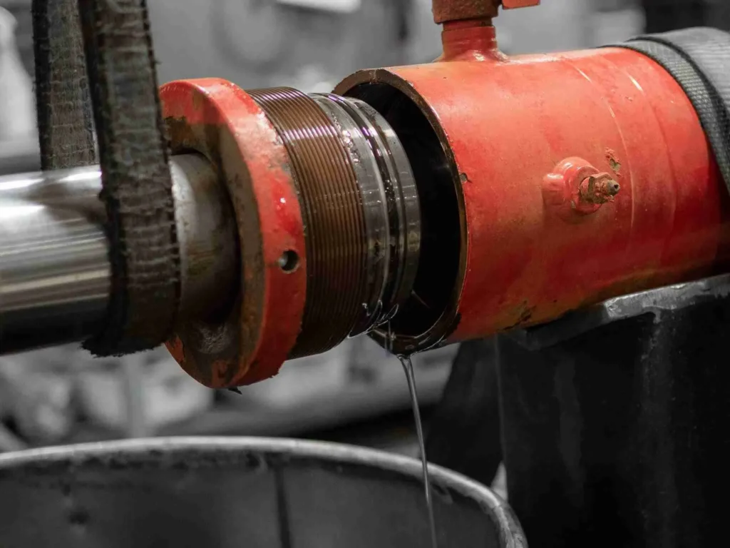
Immediate Leakage: Check the Assembly First
If oil leakage persists from the very first operation, first verify the model, installation direction, component sequence and assembly path. Inspect the threads, sharp edges of grooves and any nicks on the lip, whilst also confirming whether any pre-existing defects on the rod surface have been rectified. For example, if a new seal exhibits localised, neat cuts, the surface it has passed over should be re-examined. Any residual assembly oil should be cleaned away before observation; the continuous formation of new oil droplets should not be broadly attributed to running-in.
Early Recurrence: Compare the Damage Pattern
If leakage recurs after operation, retain details of the seal’s installation orientation, photographs of the damage and operating conditions. If both the new and old seals show uneven wear on the same side, check the corresponding guide clearance, rod components and installation loads; if there is fine, dense surface wear accompanied by abnormal particle detection, inspect the hydraulic fluid and potential sources of contamination; if the seal is swollen or sticky, verify the seal material and the medium it is in contact with. The pattern of damage determines what to investigate, whilst measurement and recording are essential for confirming the cause.
Leakage Under Load or Heat: Reproduce the Real Conditions
The absence of leakage on the repair bench does not constitute acceptance under actual operating conditions once the unit is reinstalled. If the fault recurs during hot-start, heavy-load operation or directional change, record the pressures, temperatures, speeds and loads in both chambers at that time, and check whether these exceed the operating limits of the sealing system. If dimensions, assembly and operating conditions all meet requirements yet abnormal failure persists, then verify the seal material, storage conditions and batch quality.
If the location of recurrence is actually a joint, or if the change in position is due to a control valve, the original diagnosis should be revised, and the repeated replacement of the cylinder internal seals should be discontinued. Repair is considered complete when the source of the leak has been rectified and a re-test under the original fault conditions meets the requirements.
Preventive Maintenance That Reduces Future Leakage
Preventive maintenance should focus on controlling contamination, protecting the rod surface, maintaining correct load distribution, and monitoring changes in pressure and temperature. Adjust inspection schedules based on the maintenance requirements in the equipment manual, taking into account the operating environment and intensity; there is no need to frequently disassemble hydraulic cylinders that are in good working order merely for the sake of ‘prevention’.

1. Inspect the Rod and Wiper Before Damage Spreads
Include scratches on the rod surface, rust spots, damage to dust seals and fresh oil stains at connection points in routine visual inspections. Following operations involving mud and sand, pay particular attention to deposits on the rod surface and the dust-scraping edges; clean the cylinder after shutting down in accordance with the safety procedures outlined above to avoid repeatedly rubbing sand particles across the rod surface. If pitting corrosion, coating flaking or persistent oil dripping is detected, arrange for measurement and repair; do not substitute these measures with simply wiping the area dry or repeatedly topping up the oil.
2. Maintain Oil Cleanliness and Effective Filtration
Use clean tools, suitable transfer filtration equipment and port caps during oil refilling and maintenance. Inspect the tank breather, which is responsible for limiting the ingress of external contaminants during tank ventilation. Take samples as specified and record trends in particulate matter and moisture content; base oil and filter element replacement intervals on the manual, then adjust them in light of test results and contamination incidents.
Monitor the differential pressure across the filter element—that is, the pressure difference between the inlet and outlet. Thicker oil during cold starts can increase this differential; assess this in conjunction with oil temperature and alarm indications; do not simply reset the alarm and then ignore the issue. Verify the filtration rating and flow rate against cold-start conditions to avoid fitting a finer filter element without checking system compatibility.
3. Track Pressure and Temperature Under Comparable Conditions
Select typical load and operating conditions to record pressure, oil temperature and operational performance, thereby establishing a comparable baseline. If, under identical conditions, the temperature continues to rise, operation slows down or directional change impacts become more severe, inspect the cooling system, flow resistance, leaks and mechanical stresses. Do not arbitrarily increase the relief valve setting to compensate for a drop in thrust; the relief valve limits pressure by releasing oil, and its setting must comply with the requirements of the corresponding circuit.
4. Keep Mountings, Pins and Guides in Good Condition
Check for loose mountings, wear on pins and bushings, sticking at hinges and resistance in guide rails. Use only the specified lubricants at designated lubrication points; maintenance-free bearings must not be lubricated in the same way as standard pins. After replacing connecting components or adjusting guide rails, re-check alignment and interference throughout the entire stroke, and tighten in accordance with the relevant specifications.
5. Protect Idle Cylinders and Keep a Maintenance Record
During long-term storage, minimise rod exposure whilst maintaining a safe orientation permitted by the equipment, and apply rust-preventative protection compatible with the seals as required. Protect spare cylinders from moisture and impact, and seal the oil ports; follow the instructions for that specific model regarding storage orientation, whether the cylinder should be filled with oil, and periodic operational checks to avoid applying the storage method for one type of cylinder to all configurations.
Maintenance records must include, at a minimum, operating hours, inspection locations, photographs, hydraulic fluid test results and corrective actions. Should an oil leak at a specific location gradually worsen, or if the recurrence interval shortens following repairs, escalate the issue to a fault diagnosis. When confirming replacement specifications with GY Hydraulic, provide drawings, installation dimensions, load, stroke, speed, hydraulic fluid and temperature conditions; this is more effective than simply providing a single photograph of the exterior.
Hydraulic Cylinder Leakage FAQs
Q1: Can a Hydraulic Cylinder Leak Without Showing Oil Outside?
Yes, in the case of internal leakage, there may be no visible oil traces on the outside. In common double-acting cylinders, the fluid bypasses the piston and flows into the low-pressure chamber, remaining inside the cylinder. Symptoms such as slow movement under load, insufficient thrust or positional changes may prompt an inspection; however, a definitive diagnosis requires distinguishing between leakage from the hydraulic cylinder itself and leakage from circuit components such as control valves.
Q2: How Much Hydraulic Cylinder Leakage Is Acceptable?
There is no universal acceptable limit; judgement should be based on the acceptance criteria for the specific model. Internal leakage is measured by the flow rate under specified pressure, oil temperature, position and seal configuration, with millilitres per minute being the standard unit. Certain piston ring designs permit a degree of internal leakage; however, as static requirements for lip seals differ, values must not be interchanged. Persistent external seepage or dripping should be investigated, whilst a thin oil film on the rod surface must be distinguished from oil accumulation.
Q3: Can the Wrong Hydraulic Fluid Cause Cylinder Leaks?
Yes; material incompatibility and viscosity unsuitable for the operating conditions both increase the risk. ** If seals swell, become sticky or offer increased resistance after an oil change, verify the specific material grade, the hydraulic fluid and the assembly lubricant. When selecting oil, check the type, viscosity and temperature range; do not mix fluids without prior confirmation. Damaged seals require repair; switching back to the correct fluid will not automatically repair them.
Q4: Why Does a New Hydraulic Cylinder Seal Leak?
First, check the assembly, specifications and any pre-existing defects. A new seal may leak again if it has been nicked by threads, fitted in the wrong direction, does not match the groove, or is operating against a scratched rod surface. Verify against the drawings and part numbers, then check the guide clearance and actual operating conditions; persistent dripping cannot be explained solely by the notion that ‘new parts need running-in’.
Q5: Can a Scratched Rod Be Polished Instead of Replaced?
Minor defects may be assessed for professional refinishing, provided that dimensional, coating and surface requirements are still met after treatment. Deep scratches, pitting or coating flaking cannot usually be resolved by simple polishing. Request the repairer to specify the extent of the damage and the measured results after treatment; do not rely on feel or gloss as criteria for acceptance.
Q6: Does Cold Weather Cause Hydraulic Cylinder Leakage?
Low temperatures increase the risk of leakage, particularly when seals or hydraulic fluid are unsuitable for the actual start-up temperature. Reduced seal flexibility and thickened hydraulic fluid can both affect start-up performance. Verify the minimum start-up temperature against material and fluid requirements, and follow procedures for preheating and gradual loading; even if performance improves after warming up, further inspection is still required, and existing damage must not be ruled out on this basis alone.
Q7: When Should a Leaking Cylinder Be Rebuilt?
Consider a rebuild when components or clearances other than the seals require restoration. Rebuilding involves disassembly, inspection, measurement, repair or replacement of necessary parts, as well as assembly and testing. Disassembly of the cylinder is not necessarily required if only the joint seals are damaged; however, if the rod face is damaged or the guide clearance exceeds the limit, simply replacing the seals is insufficient. In cases of cracks, severe deformation or dimensions that cannot be restored, the manufacturer must assess reparability and propose replacement options.
Q8: How Much Does It Cost to Reseal a Hydraulic Cylinder?
The price of a seal kit does not equate to the total repair cost, and there is no reliable standard quotation. The cost depends on the cylinder type, dimensions, materials, difficulty of disassembly and reassembly, local labour rates and the condition of the hardware. Provide the model number, drawings and photographs of the fault, and request a breakdown of costs for disassembly and inspection, seals, assembly, testing, transport and equipment removal and installation. If hardware damage is discovered during disassembly, confirm the scope of repairs and the price separately before comparing replacement options.
Choosing a Trusted Hydraulic Cylinder Manufacturer
From standard hydraulic cylinders to custom solutions, we help you improve equipment performance, delivery reliability, and batch consistency
Explore Rivmate Cases

Hey There, I'm Melody!
We are a hydraulic cylinder manufacturer. For over 20 years, we have focused on producing reliable hydraulic cylinders. Need a hydraulic cylinder solution? Feel free to contact us.