Home / What Are the Different Types of Hydraulic Cylinders?
What Are the Different Types of Hydraulic Cylinders?
- Author: GY Hydraulic
- 20+ Years of Manufacturing
Common types of hydraulic cylinders include single-acting, double-acting, tie-rod, welded, and telescopic, but these terms correspond to different classification criteria. Single-acting and double-acting describe the drive method: the former relies on hydraulic power in only one direction, while the latter relies on hydraulic power for both extension and retraction. Rod-type and welded-type describe the cylinder’s mounting structure; telescopic cylinders use multiple sleeves to provide a long stroke within a short retracted length. Therefore, a single hydraulic cylinder can belong to multiple categories simultaneously—for example, a double-acting telescopic cylinder.
Which type you should choose depends on the motion required by the equipment, the load it must bear, and the available installation space. For example, when active pushing or pulling of a load is required, a double-acting design should be prioritized; when installation length is limited but a long extension distance is needed, a telescopic design should be evaluated. In this article, GY Hydraulic will guide you through the operating principles, structural differences, and applicable scenarios of common hydraulic cylinders to help you narrow down your selection based on actual operating conditions.
Table of Contents
The Main Ways Hydraulic Cylinders Are Classified
Hydraulic cylinders are typically classified by their operating principle, cylinder body mounting configuration, and the number of piston rod and extension stages. These classifications can be used in combination; they do not represent mutually exclusive product types. For example, the term “double-acting, single-rod, welded hydraulic cylinder” describes how it is driven, how the piston rod is arranged, and how the cylinder body is mounted. When comparing products, you should first confirm which classification criteria the manufacturer is using to avoid treating “single-acting” and “welded” as mutually exclusive options.
① By Operating Principle: Single-Acting or Double-Acting
Based on the direction of hydraulic fluid drive, hydraulic cylinders can be classified as single-acting or double-acting. Single-acting cylinders use hydraulic pressure to generate driving force in only one direction, while the opposite direction relies on springs, gravity, or external mechanisms; double-acting cylinders, on the other hand, use hydraulic pressure to drive in both directions. For example, a lifting mechanism that can return under the weight of the load itself can use a single-acting cylinder, whereas a horizontal mechanism requiring active pushing or pulling is typically better suited for a double-acting cylinder. You can start by determining “what force is responsible for the return stroke”: if there is no reliable external force throughout the entire return stroke, you should avoid selecting a single-acting design that relies on the load for return.
② By Body Construction: Tie-Rod or Welded
Based on the cylinder body connection method, common configurations include tie-rod and welded types. Tie-rod types use long tie rods on the outside of the cylinder barrel to clamp the end caps, which generally facilitates disassembly and maintenance; welded designs connect the cylinder barrel to part of the end cap via welding, typically offering a more compact profile—though this does not mean all end caps are non-removable. For industrial equipment with ample space where standard replacement is a priority, tie-rod designs should be considered first; for mobile equipment with limited installation space, welded designs should be prioritized. Do not judge pressure rating or service life based solely on the structural name; instead, verify the specific model’s rated pressure, mounting dimensions, and maintenance methods.
③ By Rod Arrangement: Single-Rod or Double-Rod
Based on piston rod arrangement, cylinders can be classified as single-rod or double-rod types. In a single-rod design, the piston rod extends from only one end; the effective pressure area—that is, the area where hydraulic pressure actually generates thrust—on both sides is typically different, so the force and speed during extension and retraction may also differ. In a double-rod design, the piston rod extends from both ends; if the rod diameters at both ends are the same, the effective areas on both sides are equal, and under the same oil flow rate, the theoretical reciprocating speeds are the same. If your equipment requires nearly consistent bidirectional motion characteristics, you may evaluate a double-rod design with equal diameters; however, you must account for the travel space required for the piston rods at both ends and cannot simply compare the cylinder body length.
④ By Stage Configuration: Single-Stage or Telescopic
Based on the number of extension stages, cylinders can be classified as single-stage or telescopic. A single-stage cylinder has only one stage of extension; a telescopic cylinder extends sequentially through multiple nested sleeves, achieving a longer stroke within a limited retracted length, making it suitable for equipment with installation length constraints, such as dump trucks. Telescopic cylinders can be either single-acting or double-acting; do not assume they retract solely by gravity.
When selecting a cylinder, you should specify both the required stroke and the available installation length when fully retracted, rather than simply requesting “sufficient extension.” If a single-stage cylinder can already fit within the available space and meet the stroke requirement, there is no need to choose a telescopic cylinder solely to increase the number of stages. If a telescopic cylinder is necessary, you must also verify that the thrust and speed of each stage meet the actual load requirements.
Single-Acting Hydraulic Cylinders
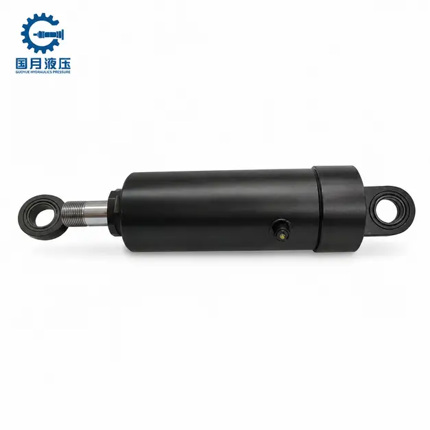
A single-acting hydraulic cylinder uses hydraulic fluid to generate driving force in only one direction; in the opposite direction, it relies on a spring, the load’s own weight, or an external mechanism to return to its original position. A common design extends when fluid is supplied and retracts when fluid is drained, but there are also tension-type designs where retraction is hydraulically driven. Therefore, “single-acting” describes the number of hydraulic drive directions and does not imply that the cylinder can only push outward.
a. How It Works
Take a common lifting cylinder as an example: the pump delivers fluid into the working chamber—the internal space where hydraulic pressure pushes the piston or plunger—causing the cylinder to extend and lift the load. During the return stroke, the control valve opens the return line, and the load or a spring pushes the cylinder to retract, draining the fluid back into the reservoir. Stopping the oil supply does not automatically trigger retraction: If the return line remains closed, or if the return force is insufficient, the cylinder will not retract properly.
b. Where It Fits
Single-acting cylinders are suitable for mechanisms that require hydraulic power in only one direction, while a reliable return force is available in the opposite direction. For example, a dump truck’s lifting cylinder can retract under the weight of the truck bed, and some clamping devices can release via a spring. It typically requires connection to only one working port, resulting in a simpler piping system; however, this does not mean it lacks other openings. Some designs also include a vent port to allow air to enter and exit the non-working chamber, which must not be blocked arbitrarily.
If your mechanism is mounted horizontally, lacks springs or an external return mechanism, yet requires active retraction of the load, a standard load-return single-acting cylinder is not suitable. Even if a return force is present, do not assume the return speed is constant, as load size, mechanism angle, and return flow resistance will all affect the motion.
c. What to Check Before Choosing
First, confirm that the return force is sufficient throughout the entire return stroke, then verify the thrust and stroke. For example, for a dump truck, it is not enough to verify whether it can lift a fully loaded truck; you must also verify that, after unloading, when the empty truck bed is nearly level, the cylinder can overcome seal friction and return flow resistance to complete the retraction. When requesting a quote, you can provide the supplier with the minimum return load, installation angle, stroke, operating pressure, and target return time so they can verify the cylinder’s return capacity.
A common mistake is selecting the cylinder bore size based solely on the lifting weight while neglecting return conditions and descent control. For mechanisms that rely on gravity for descent, you should also confirm that the control valve can limit the descent speed; when servicing lifting equipment, use the specified mechanical supports and do not rely solely on the hydraulic cylinder to hold the load.
Double-Acting Hydraulic Cylinders
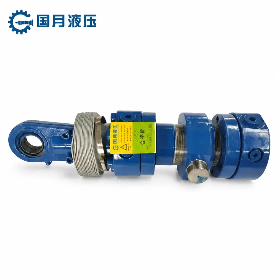
A double-acting hydraulic cylinder uses hydraulic fluid to generate driving force in both the extension and retraction directions, enabling it to actively push and pull loads. It does not rely on springs or the load’s own weight to complete the return stroke, making it suitable for equipment that requires bidirectional operation. For example, a horizontal material-pushing mechanism that must both push material out and actively pull the push plate back can utilize a double-acting design.
a. How It Works
A typical double-acting cylinder usually has two working ports, each connected to a chamber on opposite sides of the piston. A directional control valve—which changes the direction of fluid flow—supplies fluid to one side while allowing fluid from the other side to return to the reservoir, thereby controlling extension or retraction. You can think of it as hydraulic pressure alternately pushing the piston from both sides. Therefore, when troubleshooting slow movement in a particular direction, you must check both whether the oil supply is sufficient and whether the return flow on the other side is unobstructed.
b. Why Extension and Retraction Differ
In common single-rod double-acting cylinders, the piston rod occupies part of the cross-sectional area on one side, resulting in different effective pressure areas—that is, the areas where hydraulic pressure actually generates driving force—on each side. At the same supply pressure—and ignoring return back pressure and friction—the extension thrust is greater than the retraction pull; at the same inflow rate, the retraction speed is typically faster. When selecting a cylinder, you should verify the required thrust, pull, and speeds in both directions separately; you cannot assume that “double-acting” means identical performance in both directions.
For example, assuming a bore diameter of 80 mm and a rod diameter of 40 mm, the effective area on the retraction side is 75% of that on the extension side. Under the ideal conditions described above, the retraction force is approximately 75% of the extension thrust, and the retraction speed is approximately 1.33 times the extension speed. This is an example of dimensional calculation and not actual product test data; if your mechanism requires a significant retraction force, selecting a cylinder based solely on the extension thrust may not be sufficient.
c. Where It Fits and What to Check
Double-acting cylinders are suitable for applications requiring bidirectional drive, such as horizontal feeding, active retraction, and mechanism flipping. They are also suitable for installation orientations where gravity-assisted return cannot be guaranteed; however, the double-acting design itself does not guarantee precise positioning, uniform motion, or reliable load holding. For example, even when using a double-acting cylinder in a vertical lifting mechanism, an appropriate load control valve must be configured based on the load and circuit; relying solely on stopping the pump’s oil supply is insufficient to prevent the load from dropping.
When requesting a quote, you should provide the extension load, retraction load, stroke, target speeds in both directions, as well as the mounting orientation and operating pressure. For mechanisms that require only unidirectional lifting and where the load’s own weight can reliably ensure return travel, a single-acting design may be sufficient; the advantages of a double-acting design become more evident only when active return travel or bidirectional force application is required.
Tie-Rod Hydraulic Cylinders
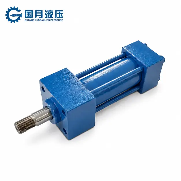
In a tie-rod hydraulic cylinder, the end caps at both ends are clamped to the cylinder barrel by long tie rods and nuts on the outside of the barrel. Here, the tie rods are connecting elements that secure the cylinder body; they are not piston rods that extend to push a load. The term “tie-rod” describes the connection structure; therefore, the cylinder can be designed as either single-acting or double-acting, and the drive type cannot be determined solely by its appearance.
a. How the Structure Works
When hydraulic pressure acts on the piston, it also exerts an outward force on the end caps. The external tie rods help maintain the connection between the end caps and the cylinder barrel through preload—that is, the clamping force applied during assembly. You can think of it as clamping the entire cylinder body with a long bolt, but the nut should not be tightened as much as possible. After repairs, reassemble according to the torque specifications and tightening sequence for the specific model; do not simply copy data from other cylinders or tighten based on feel.
b. Where It Fits
Tie-rod-type cylinders are suitable for industrial equipment where ease of disassembly and repair, standard mounting interfaces, and spare parts availability are priorities—such as clamping devices, presses, and material-handling mechanisms. Removable end caps facilitate inspection of internal components and replacement of seals, but actual maintenance efficiency still depends on available working space and the availability of spare parts. If your machine frame has limited space, you should first verify the total space occupied by the end caps, tie rods, and port fittings; in environments with silt or corrosive substances, you must also consider protection and cleaning of exposed threads.
c. Pressure Capability and Selection Checks
The fact that a cylinder is tie-rod type does not mean it is limited to low-pressure applications. For example, Parker’s 2H/3H series includes tie-rod hydraulic cylinders rated at 3,000 psi (approximately 20.7 MPa). This merely illustrates the capabilities of those specific products and cannot be generalized to all tie-rod designs. You should verify the working pressure for each specific model; if the equipment frequently undergoes emergency stops, directional changes, or is subjected to shock loads, you should also provide the supplier with peak pressure values and operating frequency.
When replacing an old cylinder, you should at a minimum verify the bore diameter, rod diameter, stroke, retracted mounting distance, mounting hole dimensions, and port specifications. For example, even if two cylinders have the same bore diameter and stroke, they may not be directly interchangeable due to differences in mounting hole spacing. When requesting a quote, provide the original cylinder model and dimensional drawings, and confirm the availability of seal kits as well as disassembly and repair requirements; this approach is more reliable than simply requesting “a pull-rod cylinder of the same size.”
Welded-Body Hydraulic Cylinders
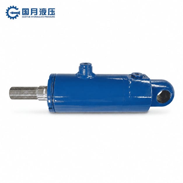
In welded hydraulic cylinders, the cylinder base is typically welded to the cylinder barrel to form a single unit, eliminating the need for external tie rods to clamp the end caps. This design generally features a more compact profile, facilitating the placement of mounting brackets and hydraulic ports. The term “welded” refers to the method of connecting the cylinder body; it can be used for both single-acting and double-acting cylinders and does not imply that the entire cylinder is permanently welded and cannot be repaired.
a. How the Structure Works
The weld joint connects the cylinder base to the cylinder barrel and withstands the forces generated by hydraulic pressure. The end of the piston rod that extends outward is typically equipped with a guide and seal assembly—a component that supports the piston rod and prevents fluid leakage; many models secure this assembly using threads or other removable structures, facilitating the removal of the piston rod and piston. When purchasing, you should confirm the specific disassembly and assembly methods; you cannot judge the difficulty of maintenance based solely on the term “welded type.” For example, replacing seals usually does not require cutting the weld seam at the cylinder base.
b. Where It Fits
Welded-type cylinders are commonly used in construction machinery, agricultural equipment, and other mobile machinery, and are particularly suitable for mechanisms with limited installation space or requiring special interface layouts. For example, when a cylinder is mounted within a narrow frame, customizing the port orientation and mounting bracket position can help avoid interference with crossbeams and hoses. However, a compact cylinder body does not necessarily mean the entire assembly will fit: you should also verify the protrusion dimensions of the fittings, the space available for hose bending, and whether interference occurs when the cylinder swings.
If the equipment already has standard mounting interfaces and you prioritize off-the-shelf replacements and quick disassembly/repair, you should compare the dimensions, lead times, and spare parts support of welded-type cylinders with those of standard rod-type cylinders. Welded-type cylinders can be used outdoors, but their corrosion resistance still depends on the coating, piston rod surface treatment, and seal protection; suitability for salt spray or frequent washing environments cannot be determined solely by the structural designation.
c. What to Check Before Choosing
Welded cylinders are not inherently more pressure-resistant or impact-resistant than tie-rod cylinders. Actual performance depends on materials, dimensions, weld quality, and overall design. For equipment that undergoes frequent directional changes or is subject to impacts, you should provide the supplier with the operating pressure, peak pressure, and cycle frequency, and confirm the applicable conditions for the corresponding model; comparing only the cylinder wall thickness or the appearance of the welds is insufficient to determine long-term reliability.
When requesting a quote, it is recommended to also request installation dimension drawings, disassembly and repair instructions, and information on the seal kit. For example, if the piston rod assembly needs to be removed from the frame in the future, sufficient maintenance space should be reserved in advance. Also, do not arbitrarily weld brackets onto the finished cylinder barrel: the heat from welding may damage the seals or cause the cylinder barrel to deform. If additional mounting points are required, have the manufacturer evaluate and complete the corresponding design.
Telescopic Hydraulic Cylinders
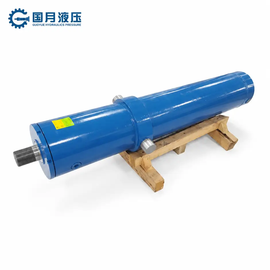
Telescoping hydraulic cylinders achieve a long stroke within a short retracted length through multiple stages of nested moving sleeves. You can think of it like a telescoping telescope: when retracted, the stages are nested inside one another; when in operation, they extend one stage at a time. It is suitable for equipment where “installation length is limited but a long travel distance is required”; however, not all long-stroke applications necessarily require a telescoping design.
a. How the Stages Work
Each movable sleeve that can extend is referred to as a stage. Conventional telescopic cylinders typically extend the stage with the largest diameter first, followed sequentially by the smaller stages; however, the specific order should be determined by the product design.The effective pressure area of each stage—that is, the area over which hydraulic pressure generates driving force—usually varies; at the same pressure, the thrust of a smaller stage is typically lower, while at the same oil flow rate, it moves faster. Therefore, if your mechanism requires constant speed throughout the entire stroke, do not assume that a constant oil supply will meet the requirements; you should have the supplier verify the speed of each stage and the control scheme.
b. Single-Acting or Double-Acting
Telescoping cylinders can be either single-acting or double-acting. A single-acting design uses hydraulic pressure for extension and relies on gravity or an external mechanism for retraction; for example, a dump truck uses the weight of the cargo bed to push the lift cylinder back. a double-acting design, on the other hand, uses hydraulic power for both extension and retraction, making it suitable for mechanisms that require active retraction. You should first confirm the source of the return force: if the equipment is mounted horizontally and lacks a reliable external return force, you should not choose a single-acting model that relies on gravity for retraction.
c. Where It Fits
Telescoping cylinders are commonly found in dump trucks, dump trailers, and waste transfer equipment. For example, in a horizontal push-off mechanism that needs to move the push plate to the far end of the body but must not occupy excessive length when retracted, a double-acting telescopic cylinder is worth evaluating. However, if a standard single-stage cylinder already meets the stroke and installation space requirements, there is no need to adopt a telescopic structure solely to increase the number of stages; more moving stages also mean more guide and seal components requiring maintenance.
d. What to Check Before Choosing
When selecting a cylinder, verify the total stroke, retracted installation length, and thrust of each stage simultaneously, rather than focusing solely on the capacity of the top stage. For example, if a material-pushing mechanism must still overcome significant resistance near the end of its stroke, you must confirm that even the lowest extended stage has sufficient thrust. When requesting a quote, provide the loads at each position, target cycle times, and installation dimensions so that the supplier can calculate the performance on a stage-by-stage basis, rather than simply quoting a single maximum load value.
You should also check stability at full extension and avoid lateral loads—that is, transverse forces deviating from the cylinder’s axis. For example, the push plate should be guided by rails; the telescopic cylinder itself should not be relied upon to prevent the push plate from tilting. When long-stroke telescopic cylinders are subjected to compressive loads, you must also verify the risk of buckling—that is, the possibility of a slender component becoming instable and bending under compression. These conditions may affect the required diameter and the overlap length between stages.
Ram, Plunger, and Displacement Cylinders
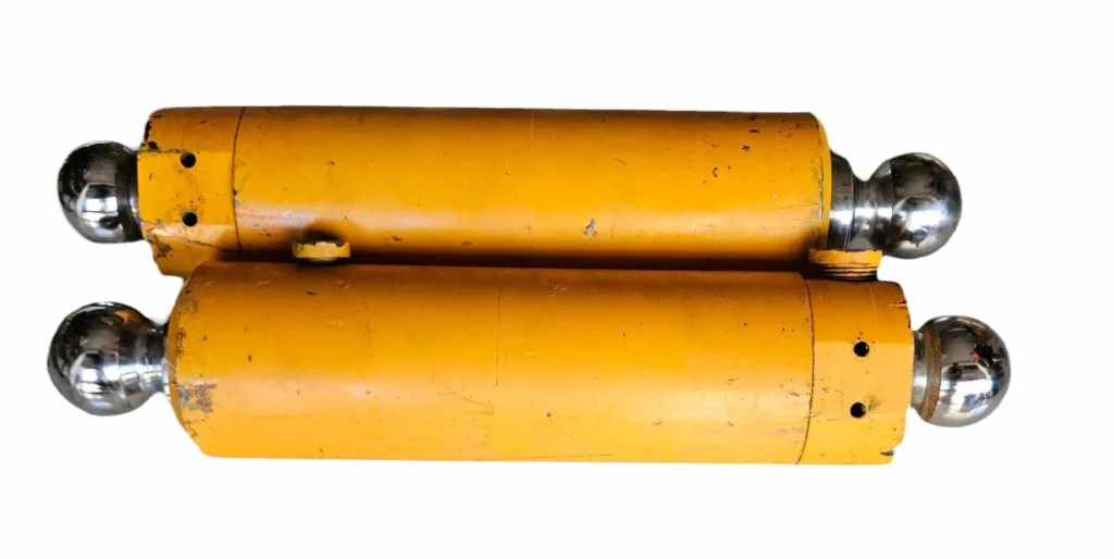
In many product specifications, the terms “Ram,” “Plunger,” and “Displacement Cylinder” refer to similar plunger-type structures and do not necessarily denote three distinct types. Among these, “Ram” is sometimes used as a generic term for hydraulic cylinders. When requesting a quote, you should verify the structural drawings and operating principles; you cannot determine whether a product is a plunger-type based solely on the term “hydraulic ram.”
How the Design Works
A typical plunger-type hydraulic cylinder does not have a piston seal separating the two oil chambers; instead, a seal at the cylinder port encloses the plunger—the rod-like component that extends and pushes the load. When fluid is supplied, the incoming fluid causes the plunger to move outward; the return stroke typically relies on gravity or other external forces to return the hydraulic fluid to the reservoir. Some positive-displacement designs still contain internal components for guidance or limiting, so they cannot simply be understood as “completely lacking any piston-like parts.” When making a determination, focus on whether there is a piston seal that separates the pressure chambers.
Why Plunger Diameter Matters
For common constant-diameter plunger designs, the effective pressure-bearing area is typically determined by the plunger diameter, not the cylinder bore diameter. For example, assuming a plunger diameter of 50 mm and an operating pressure of 10 MPa, the theoretical thrust—calculated as “pressure × area”—is approximately 19.6 kN, before accounting for losses such as friction. This is a calculation example, not test data. When selecting a model, you should request the effective area from the manufacturer; if you mistakenly use a larger cylinder bore diameter for your calculations, you may overestimate the thrust.
Where It Fits
Plunger-type cylinders are suitable for mechanisms requiring unidirectional lifting or pushing, where a reliable external force completes the return stroke, such as certain jacks, lifting devices, and presses. They do not require internal piston seals, but the plunger surface, cylinder end seals, and guide components still require maintenance. Taking lifting devices as an example, you should confirm that the platform can overcome friction and return flow resistance even under the lightest load; it is not sufficient to verify only whether it can descend under full load. Reference: Montanhydraulik Plunger Cylinder Application Notes
What to Check Before Choosing
If the mechanism requires active retraction or lacks a reliable return mechanism when installed horizontally, a standard single-acting plunger cylinder is not suitable. Horizontal installation is not inherently impossible, but the guide supports and return conditions must be verified. For long-stroke lifting applications, you should also have the supplier check for buckling—that is, the risk of buckling instability in slender pistons under compression—and ensure that the equipment’s guide rails can withstand lateral forces. For example, a lifting platform should have independent guidance; the piston alone should not be relied upon to prevent the platform from tilting. Furthermore, a thicker piston does not necessarily mean it can withstand arbitrary off-center loads.
Tandem, Duplex, and Multi-Stage Cylinder Designs
These designs address different issues: Tandem cylinders are typically used to stack output forces, Duplex cylinders are used for combined motions or to achieve multiple positions, and Multi-Stage cylinders often refer to those that achieve a long stroke through multi-stage extension. Naming conventions may vary among manufacturers, so you should make your determination based on cross-sectional diagrams, port connections, and motion descriptions—you cannot infer performance solely from terms like “dual” or “multi-stage.”
Tandem Cylinders: Combining Force
Tandem hydraulic cylinders typically arrange two or more pistons along the same axis and transmit output force via a common piston rod or mechanical connection. When the corresponding oil chambers are pressurized simultaneously and act in the same direction, the forces generated by each piston can be combined. This design is suitable for mechanisms with limited installation width where the cylinder bore cannot be increased but the axial length can be extended. For example, this design can be considered when a clamping device requires greater thrust but the frame width cannot be changed.
Increasing thrust also means increasing the fluid supply requirement. Assuming that the effective area of each of the two drive chambers is 2,000 mm² and the supply pressure is 10 MPa—while neglecting return back pressure and friction—the total theoretical thrust is 40 kN; to maintain the same speed, the combined flow rate required for both chambers is twice that of a single chamber. This is a sample calculation. When selecting a model, one should simultaneously verify the pump flow rate, the load-bearing capacity of the connecting components, and the total installation length; the term “series” here does not mean connecting the return flow from the first cylinder directly to the second cylinder.
Duplex Cylinders: Combining Separate Motions
Duplex cylinders typically combine two sets of independently driven piston mechanisms. Unlike series configurations with a common output, the two pistons in a typical duplex design are not rigidly connected as a single unit; multiple positions can be achieved through combinations of stroke and control. For example, for a pushing mechanism requiring three positions—“retracted, partially extended, and fully extended”—you can evaluate corresponding duplex solutions. However, not all duplex products have the same structure or number of positions; you should ask the supplier to provide a schematic illustrating the motion when each port is supplied with fluid.
When selecting a model, you should list each target position, the thrust required for that position, and the sequence of operations. If precise stopping at any position is required, a combination of a few fixed strokes is usually insufficient; position detection and control solutions must also be evaluated. Also, do not confuse duplex cylinders with “double-rod cylinders”: double-rod cylinders typically have piston rods on both ends of the same piston, which does not imply that the two ends can operate independently.
Multi-Stage Cylinders: Extending Available Travel
In the context of common telescopic cylinders, a multi-stage design involves nesting the moving sleeves in layers to reduce the retracted length and increase the total stroke. For example, a dump truck that requires a long lifting stroke but lacks sufficient space to install a standard single-stage cylinder with the same stroke can utilize a multi-stage telescopic structure. The primary purpose is usually to increase available stroke; the thrust of each stage should not be directly added together as if it were a series-connected power-amplifying cylinder.
You should verify the stroke, effective pressure area, and corresponding load for each stage individually, because when a conventional telescopic cylinder switches to a smaller stage, the thrust typically decreases at the same pressure, while the speed typically increases at the same flow rate. If the application requires maintaining high thrust or a stable speed throughout the entire stroke, appropriate structural and control designs are necessary.
Mill-Type and Heavy-Duty Hydraulic Cylinders
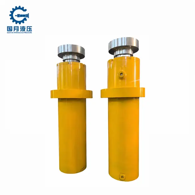
Metallurgical-grade hydraulic cylinders are typically designed for demanding industrial applications such as steel processing, whereas “heavy-duty” is a broader performance description that does not imply a uniform structure or fixed pressure rating. Metallurgical-grade cylinders may feature bolted or welded constructions, and heavy-duty series are also available among tie-rod-type products. When selecting a model, you should verify the specific model’s load-bearing capacity and environmental requirements; you cannot determine suitability based solely on the “heavy-duty” label.
How the Construction Supports Heavy Duty
These products typically feature a more robust cylinder body, end connections, and guide designs to accommodate heavy mechanical loads and repetitive operation. For example, some metallurgical-grade cylinders have end caps bolted to thick steel flanges; a flange is a rim-like structure used for connection and fastening, and this design also facilitates disassembly and maintenance. However, a robust structure does not mean it can withstand arbitrary lateral forces; you must still ensure that the load is transmitted along the cylinder’s axis and that lateral movement is constrained by the equipment’s guide rails.
Where It Fits
Metallurgical or other heavy-duty hydraulic cylinders are suitable for applications such as steel production lines, heavy-duty material-pushing mechanisms, and large clamping equipment. For example, steel-pushing mechanisms may be subjected to high loads, frequent directional changes, and scale dust simultaneously. You should provide the supplier with information on operating frequency, load variations, and contamination levels so they can select appropriate seals, dust wiper components, and piston rod surface protection. If the application involves only low-frequency, light-load operation, standard industrial hydraulic cylinders are sufficient; there is no need to increase weight, installation space, or procurement costs simply for the sake of “greater durability.”
Heat and Shock Require Specific Checks
Just because a product is used in a steel mill does not mean its standard configuration can directly withstand high temperatures. For example, the standard temperature range listed in the Parker MMB catalog is −20°C to +80°C; this data applies only to the corresponding configurations within that series and cannot be generalized to all metallurgical-grade products. When installing near hot steel billets, you should specify the oil temperature, ambient temperature, and heat radiation conditions separately so that the supplier can confirm whether thermal insulation or special seals are required; if flame-retardant hydraulic fluid is used, you must also verify the compatibility between the seals and the fluid.
Impact forces also require separate evaluation. For example, if a heavy-duty push mechanism stops abruptly at the end of its stroke, the inertia of the moving parts will act on the cylinder and the mounting structure. You should provide the moving mass, operating speed, and stopping distance so that the supplier can verify whether the end-of-stroke cushioning—that is, the design intended to decelerate the cylinder as it approaches the end of its stroke—is sufficient. Do not assume that a thicker cylinder barrel can substitute for proper deceleration control.
What to Specify Before Ordering
When requesting a quote, it is recommended to list the push/pull load, stroke, operating pressure and peak pressure, cycle frequency, mounting orientation, hydraulic fluid, and temperature conditions in a single operating conditions sheet, and to request installation drawings, seal kit part numbers, and maintenance instructions. For example, when a long-stroke cylinder is used to push a heavy load, you should also verify the risk of buckling—that is, the possibility of the piston rod buckling under compression.
Smart and Position-Sensing Hydraulic Cylinders
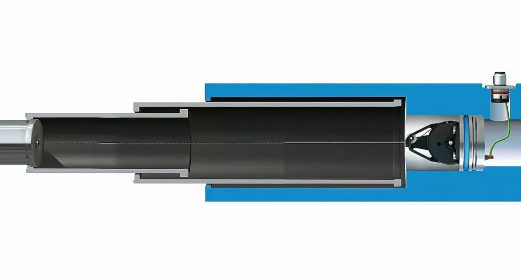
Position-sensing hydraulic cylinders use sensors to detect the position of the piston or piston rod and transmit the signal to the control system. The term “smart” typically refers to the addition of functions such as signal processing, communication, or condition monitoring on top of this basic capability, though the scope of features varies by product. It also does not refer to a specific cylinder design: position detection can be configured on various types of cylinders, including welded and tie-rod types.
How Position Sensing Works
Position detection can utilize built-in or external sensors. Common magnetostrictive sensors measure stroke non-contact by detecting the position of a magnetic ring that moves with the piston, eliminating the need for measuring contacts to slide along the rod surface. For example, a material-feeding mechanism can use continuous position feedback to determine how far the pusher plate has moved. If you only need to confirm “fully extended” or “fully retracted,” a limit switch may be sufficient, and full-stroke measurement is not necessarily required.
Position Feedback Does Not Equal Automatic Control
Simply installing a sensor does not mean the hydraulic cylinder will automatically and accurately stop at the target position. To achieve automatic positioning, a controller must compare the target position with the actual position and then adjust the valve or pump; this process is called closed-loop control. For example, as the push plate approaches the target position, the controller can reduce the oil supply to slow its speed. However, the final stopping performance is also affected by the load, valve response, hydraulic fluid compression, and mechanical clearance; therefore, you should ask the supplier to confirm the positioning performance of the entire system, rather than relying solely on sensor specifications.
Where It Fits
Position-sensing designs are suitable for equipment requiring intermediate positioning, stroke monitoring, or coordinated movement of multiple cylinders. For example, when two hydraulic cylinders work together to lift a platform, measuring their positions separately provides the basis for the control system to correct height differences between the two sides; installing only two sensors does not automatically achieve synchronization. If the equipment performs only simple fully extended or fully retracted motions and does not require continuous position data, you should first evaluate end-of-stroke detection solutions to avoid adding unnecessary wiring and maintenance costs.
What to Check Before Choosing
When selecting a sensor, distinguish between resolution, measurement accuracy, and repeatability: Resolution is the smallest distinguishable change in position; accuracy reflects how closely the reading matches the actual position; and repeatability indicates whether the system can stop at similar positions during repeated operations. For example, a display resolution of 0.01 mm does not mean the entire machine can stop accurately within ±0.01 mm. You should clearly define the permissible positional error, motion speed, and load conditions before having the supplier match the sensor to the control system.
You should also verify the measurement range, power supply, output interfaces, connectors, and environmental conditions. For example, if the controller accepts a 4–20 mA current signal but the sensor outputs a CAN bus communication signal, the two cannot be directly wired using the same type of interface. For built-in sensors, verify the voltage rating and maintenance procedures; for external sensors, ensure sufficient installation space is reserved and protect them from collisions. Additionally, establish protocols for how the equipment will stop or maintain the load in the event of signal loss; ordinary position feedback should not be relied upon as an independent safety protection measure.
Mounting Styles and How They Affect Cylinder Choice
When selecting a mounting configuration, first determine whether the cylinder needs to swing during operation, and then consider how the thrust and pull forces are transmitted to the frame. Linear motion mechanisms typically use fixed mounting; mechanisms where the angle changes during movements such as tilting or lifting usually require articulated mounting. For example, a push plate moving along a guide rail and a tilting plate rotating around a hinge cannot use the same mounting method even if they carry the same load.
Flange Mounts: Fixed Alignment for Straight-Line Motion
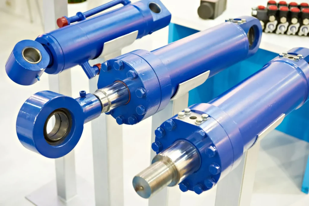
Flange mounting secures the cylinder to the frame using flanges and bolts at the cylinder ends and is suitable for mechanisms where the load moves along a fixed straight line, such as press-fitting or material-feeding devices with guide rails. During installation, ensure that the cylinder’s axis is aligned with the direction of the load’s movement; do not rely on tightening the bolts to forcibly correct misalignment. The selection of the front and rear flanges also depends on the primary thrust or pull direction; you should verify this based on the specific model’s load requirements rather than simply choosing the end with the most convenient bolt hole layout.
Foot Mounts: Check the Base and Load Path
Foot mounting secures the cylinder using feet on the sides of the cylinder body and is suitable for equipment with a flat, rigid mounting base. However, since the cylinder axis is typically higher than the mounting surface, thrust and pull forces generate bending moments—mechanical forces that cause the cylinder body or mounting base to rotate or bend. For example, when a horizontal material-pushing cylinder is subjected to repeated forces, both the base and fasteners must withstand this effect. You should verify the base stiffness, bolt requirements, and whether thrust keys are needed to withstand axial thrust.
Clevis and Trunnion Mounts: Allow the Cylinder to Pivot
Clevis or fork mounts are connected via a pin, while trunnion mounts are supported by trunnions on both sides of the cylinder body; both allow the cylinder to pivot with the mechanism. For example, when a tilting platform is raised, the angle of the cylinder continuously changes, so the connections at the cylinder mounting end and the rod end must allow for corresponding rotation. Standard pin connections are primarily suited for pivoting within a single plane; if spatial angular deviations exist, consider spherical bearings that allow for a certain degree of angular adjustment; however, you must verify that their permitted swing angle aligns with the load-carrying capacity.
For trunnion mounts, also check the support position and alignment to prevent the mounting bracket from subjecting the trunnion to excessive bending forces. You should have the supplier confirm the trunnion position, mounting bracket spacing, and rod-end connection method, and verify the entire motion cycle—rather than simply checking whether the cylinder fits when fully retracted.
Mounting Changes Affect Rod Stability and Service Access
Even with the same rod diameter and stroke, this does not guarantee that the same compressive load can be withstood under different mounting configurations. Mounting and guidance conditions affect the support state of the piston rod, which in turn affects the risk of buckling—that is, the possibility of a slender rod becoming instable due to bending under compression. For example, when a long-stroke material-feeding mechanism is modified to use a different support method, stability must be recalculated; the selection conclusions from the original cylinder cannot be directly applied.
When requesting a quote, you should provide the mounting point coordinates, pin or bolt dimensions, range of motion, and maximum load, and request verification of interference at the fully retracted, fully extended, and intermediate positions. At the same time, ensure sufficient space is reserved for hose bending, pin removal, and seal maintenance. For example, even if the cylinder body fits into the frame but the pin cannot be removed, this will still pose difficulties for subsequent maintenance.
How to Choose the Right Hydraulic Cylinder Type
When selecting a hydraulic cylinder, you should first determine the motion and load requirements, then compare the design, installation space, and maintenance conditions. Different types can be combined; for example, a single cylinder can be “double-acting, welded, and equipped with a position sensor” all at once. You need to specify these characteristics individually, rather than choosing between “single-acting” and “welded.”
Start With Motion and Return Requirements
First, determine whether the cylinder needs to perform work in one direction or push and pull in both directions. If the load’s own weight, a spring, or an external mechanism can provide sufficient return force throughout the entire return stroke, a single-acting cylinder may be considered; if active retraction is required, a double-acting cylinder should generally be selected. For example, a single-acting cylinder that relies on the body’s own weight for the return stroke may be suitable for a dump truck lifting mechanism, whereas a horizontal material-feeding mechanism without other return devices will require a hydraulically driven return stroke. Do not merely verify whether the cylinder can extend; also confirm that it can return to its starting position under the lightest load and at the most unfavorable angle.
Match Force and Speed to the Hydraulic Supply
Thrust primarily depends on pressure and effective pressure area—that is, the area over which the hydraulic pressure actually generates driving force; speed primarily depends on the flow rate entering the cylinder and this area. For example, assuming a required thrust of 20 kN and an available pressure of 10 MPa—while neglecting friction and return line back pressure—the theoretically required area is 2,000 mm², corresponding to a piston diameter of approximately 50.5 mm. This is only a preliminary calculation and cannot be used directly as the final specification; it must be verified against actual losses, peak loads, and design margins.
If you choose a double-acting single-rod cylinder, you should also verify the extension thrust, retraction pull, and speeds in both directions separately. While increasing the cylinder bore diameter can increase thrust at a given pressure, it will reduce speed at a given flow rate. **For example, if a material-feeding mechanism requires both high thrust and rapid reciprocation, you must verify the oil supply capacity of both the pump and the valve; simply replacing the cylinder with a larger one is not sufficient.
Check Stroke, Space, and Mounting
Simultaneously verify the required stroke and the installation distance when the cylinder is fully retracted. When a standard single-stage cylinder meets the space requirements, prioritize evaluating its structure and ease of maintenance; if the retracted length is limited but a long stroke is required, then consider a telescopic cylinder. For example, when using a telescopic cylinder for a long-distance unloading mechanism, verify the thrust at each stage individually; do not rely solely on the capacity of the topmost stage.
The mounting configuration must align with the mechanism’s motion: linear guidance mechanisms can use fixed mounting, while tilting mechanisms typically require connections that allow for oscillation. You should check for interference throughout the full stroke and have the supplier verify the risk of buckling—that is, the possibility of piston rod bending instability— when the long rod is under pressure. Do not rely on thickening the piston rod to compensate for obvious installation misalignment or missing external guidance.
Select the Construction Based on the Operating Environment
For industrial equipment that prioritizes standard mounting interfaces and ease of maintenance, prioritize comparing the pull-rod type; for equipment requiring a compact installation, special mounts, or specific port layouts, focus on evaluating the welded type. For heavy loads, frequent impacts, or harsh environments, verify the suitability of heavy-duty series. For example, for mechanisms operating near hot steel billets, clearly specify the oil temperature, ambient temperature, and thermal radiation conditions to the supplier; do not assume that “metallurgical-grade” products automatically possess the required heat resistance.
Specify Control and Maintenance Needs
If only full extension and full retraction are required, end-of-stroke detection may be sufficient; if intermediate positioning or multi-cylinder coordination is needed, evaluate continuous position sensors and the corresponding control systems. For example, for a dual-cylinder lifting platform, clearly specify the allowable height difference between the two sides before selecting a synchronization solution; do not assume that two identical cylinders will automatically synchronize.
Hydraulic Cylinder Type Comparison by Application
When comparing hydraulic cylinders by application, the focus should be on matching the drive method, installation space, and control requirements, rather than assigning a single type to each piece of equipment. For example, dump trucks can use single-acting telescopic cylinders, while industrial material-feeding mechanisms can use double-acting tie-rod cylinders. “Single-acting” and “double-acting” describe the direction of hydraulic drive, while “tie-rod type” and “welded type” describe the connection structure; these characteristics can be combined as needed.
Application Comparison Table
The table below can be used for preliminary screening. In this table, stroke refers to the distance the cylinder travels from fully retracted to fully extended; closed-loop control refers to the use of sensors to provide feedback on the actual position, which the control system then uses to correct the motion. The applications listed in the table are selection examples and do not imply that specific equipment must adopt this design.
| Application | Types to Prioritize | Why It’s Suitable | Key Considerations for Selection |
|---|---|---|---|
| Dump Trucks, Dump Trailers | Single-acting telescopic cylinders | Short retracted length, providing a long lifting stroke; relies on the body’s own weight for return | Whether the empty body can fully retract; whether the thrust at each stage matches the lifting process |
| Horizontal Material Pushing, Active Retraction Mechanisms | Double-acting tie-rod or welded type | Both extension and retraction are hydraulically driven | Verify thrust, pulling force, and reciprocating speed separately; do not use load-return single-acting cylinders when there is no external return force |
| Industrial Clamping, Standard Production Equipment | Rod-type; select single-acting or double-acting based on the application | Facilitates the use of standard mounting interfaces and facilitates disassembly and maintenance | Mounting dimensions, operating frequency, and seal kit availability; do not assume direct interchangeability between different brands |
| Linkage Mechanisms for Construction and Agricultural Machinery | Double-acting welded type | Facilitates compact layout and customized mounting connections | Swing angle, peak pressure, pin dimensions, and outdoor protection |
| Long-distance Unloading for Garbage Transfer Trucks | Double-acting telescopic cylinders | Achieves long stroke within limited retraction space and actively retracts the push plate | Thrust at minimum extension, speeds at each stage, and push plate guidance |
| Jacks and Unidirectional Lifting Devices | Single-acting plunger or piston type | Requires hydraulic power in only one direction; return stroke relies on the load or a reset mechanism | Return capacity under the lightest load, and mechanical support after lifting |
| Steel Production Lines, Heavy-duty Material-feeding Mechanisms | Metallurgical-grade or field-proven heavy-duty cylinders | Can be configured for repeated heavy loads, shock, and contaminated conditions | Considerations such as temperature, hydraulic fluid, shock frequency, and seal protection—do not rely solely on the “heavy-duty” designation |
| Precision Positioning and Multi-cylinder Coordinated Equipment | Cylinders with continuous position sensors, paired with closed-loop control | Provide feedback for mid-stroke positioning, deceleration, and synchronization correction | Overall system tolerance, valve response, and control schemes; the sensor itself cannot guarantee synchronization |
How to Use the Comparison
You can first select the application that most closely matches your needs, then review the constraints. For example, for a lifting platform, if the entire return stroke can be accomplished by the load’s own weight, a single-acting design can be evaluated; if the mechanism cannot generate sufficient return force during a certain portion of the stroke, the return mechanism must be reevaluated. Do not simply copy the cylinder type from another piece of equipment just because it shares the same name.
Before submitting a quote request, it is recommended that you confirm at least the required thrust/pull force, stroke, retracted installation distance, target cycle time, operating pressure, and return mechanism, and include details on temperature, contamination, and shock conditions. For example, even if two material-feeding devices have the same load and stroke, they may be better suited for a standard single-stage cylinder and a telescopic cylinder, respectively, due to differences in installation space or speed requirements.
Frequently Asked Questions About Hydraulic Cylinder Types
Q1. Which Type of Hydraulic Cylinder Is Most Common?
Double-acting single-rod hydraulic cylinders are one of the most common types; they can actively extend and retract and are suitable for many industrial and mobile applications. However, there is no single “most common” type that applies to all industries: tie-rod cylinders are common in industrial equipment, while welded cylinders are widely used in mobile machinery. When selecting a cylinder, you should first consider the drive direction and installation conditions, rather than choosing based solely on prevalence.
Q2. What Is the Difference Between Tie-Rod and Welded Cylinders?
Tie-rod cylinders use long external tie rods to clamp the end caps, which typically facilitates disassembly and assembly; welded cylinders usually have the cylinder base welded to the cylinder barrel, resulting in a more compact design that allows for customized installation positions. Welded cylinders are not necessarily impossible to repair, nor are tie-rod cylinders limited to low-pressure applications. You should compare the rated pressure, mounting dimensions, and maintenance methods of specific models.
Q3. Which Hydraulic Cylinder Type Is Best for Limited Space?
First, determine which dimension is constrained. If you need a long stroke but have limited retracted length, consider a telescopic cylinder; if installation width is limited, compare compact welded cylinders; for short-stroke clamping mechanisms, consider compact cylinders. When selecting a model, be sure to account for space required for fittings, hoses, and maintenance—don’t focus solely on the cylinder body dimensions.
Q4. Which Cylinder Design Is Suitable for Very Long Strokes?
Telescoping cylinders are suitable for achieving long strokes within a short retracted length; if installation space is ample, standard single-stage long-stroke cylinders may also be suitable. You should also verify stability in the fully extended state, external guidance, and the required thrust. The thrust and speed typically vary across the stages of a telescoping cylinder, so you cannot determine the model solely based on whether the total stroke meets the requirements.
Q5. Are All Hydraulic Cylinders Repairable?
Not all hydraulic cylinders are suitable for repair. Disassemblable models typically allow for seal replacement and the inspection or replacement of some internal components; however, for certain sealed designs, or cylinders with severe deformation or structural cracks, repairs may be unreliable or uneconomical. You should have the repair provider assess the damage, the manufacturer’s permitted scope of repair, and the availability of replacement parts; do not assume that just because a cylinder can be disassembled, it will be safe to use after repair.
Q6. What Is a Differential Hydraulic Cylinder?
A differential hydraulic cylinder typically refers to a double-acting single-rod cylinder in which the effective pressure areas on both sides differ: the area on the rodless side is larger, while the area on the rod side is smaller because the piston rod occupies space. Therefore, at the same supply pressure—and assuming back pressure and friction are negligible—the extension thrust is greater; at the same inflow rate, the retraction speed is faster. A differential cylinder is not the same as a differential circuit: the latter diverts the return flow from the rod side back to the non-rod side to increase extension speed while reducing the available thrust.
Q7. What Is a Cushioned Hydraulic Cylinder?
A cushioned hydraulic cylinder slows down movement as it approaches the end of its stroke—typically by restricting oil return—to reduce end-of-stroke impact. Cushioning can be provided at one or both ends, and some designs allow for adjustment. You should verify the cushioning capacity based on the moving mass, speed, and mounting orientation; do not assume that the presence of cushioning allows any load to strike the end of the stroke at high speed.
Q8. Can Different Hydraulic Cylinder Types Use the Same Power Unit?
Yes, but the pressure, flow rate, hydraulic fluid, and control circuit must be matched. A hydraulic power unit is a fluid supply system consisting of a pump, drive motor, reservoir, and related components. The same power unit can supply fluid to different types of cylinders, but single-acting and double-acting cylinders typically require different valve circuits for control. You should also verify the reservoir capacity, return flow capacity, and total flow rate requirements when multiple cylinders operate simultaneously; do not rely solely on whether the fittings can be connected.
Choosing a Trusted Hydraulic Cylinder Manufacturer
From standard hydraulic cylinders to custom solutions, we help you improve equipment performance, delivery reliability, and batch consistency
Explore Rivmate Cases

Hey There, I'm Melody!
We are a hydraulic cylinder manufacturer. For over 20 years, we have focused on producing reliable hydraulic cylinders. Need a hydraulic cylinder solution? Feel free to contact us.