Home / How Does a Telescopic Hydraulic Cylinder Work?
How Does a Telescopic Hydraulic Cylinder Work?
- Author: GY Hydraulic
- 20+ Years of Manufacturing
Telescopic hydraulic cylinders utilise the pressure of hydraulic fluid to extend a series of nested sleeves, thereby achieving a long stroke within a relatively short retracted length. You can think of it as a hydraulically driven telescopic aerial. Common designs typically begin by extending the moving stage with the largest diameter, followed sequentially by the smaller stages.
The retraction method depends on the type of cylinder. Single-acting telescopic cylinders rely on gravity or an external force to retract, whilst draining the hydraulic fluid back into the reservoir; double-acting telescopic cylinders, on the other hand, utilise hydraulic power for retraction. Consequently, not all telescopic cylinders are capable of actively pulling back a load. This design is suitable for equipment where installation space is limited but a significant lifting distance is required, such as tipper lorries. In this article, GY Hydraulic will guide you through the oil supply, staged extension and retraction processes of telescopic cylinders, as well as the key factors affecting their speed and thrust.
Table of Contents
How Does a Telescopic Hydraulic Cylinder Work?
Telescopic hydraulic cylinders utilise hydraulic pressure to extend a series of nested sleeves, transforming a short retracted length into a long stroke. In common designs, the largest moving stage typically extends first, followed sequentially by the smaller stages.
Nested Stages Create a Long Stroke From a Short Closed Length
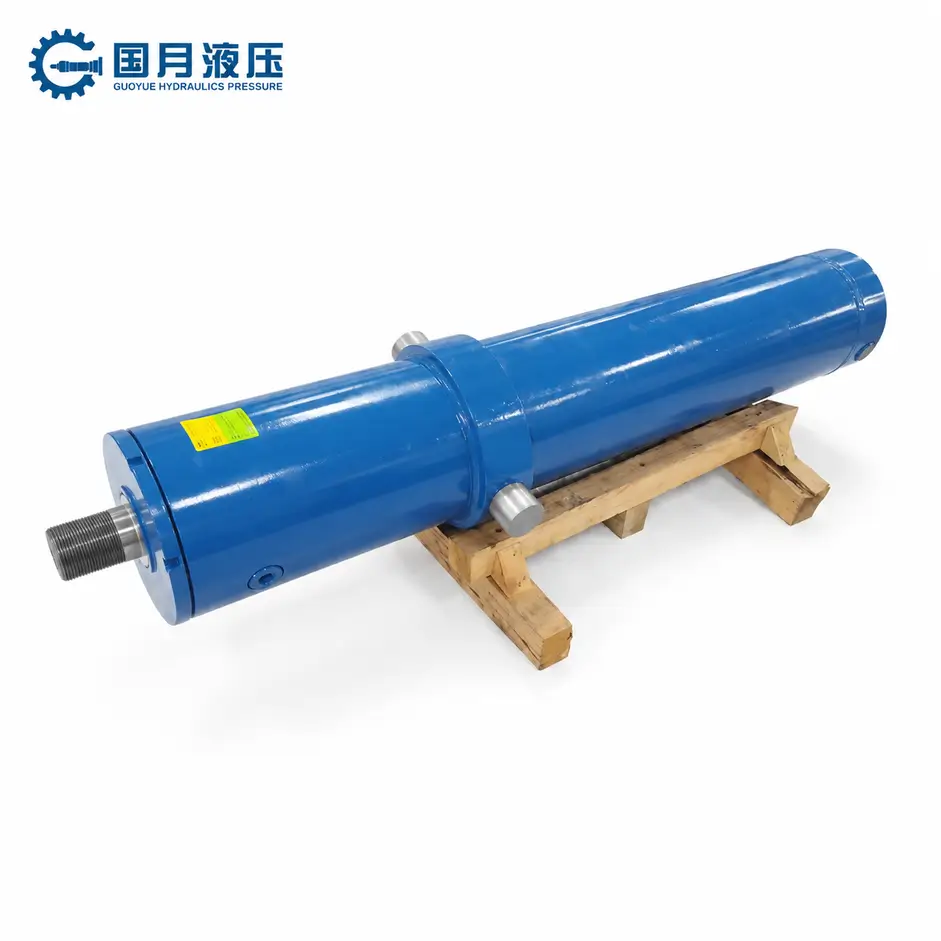
Inside the telescopic cylinder are sleeves with diameters that decrease step by step; the movable sleeves are referred to as ‘stages’. When retracted, the stages are nested inside one another; when extended, each stage increases its travel distance in sequence, with the total stroke being the sum of the relative extension strokes of each movable stage. You can think of it as a telescopic aerial, but each stage must retain a certain overlap length for support, guidance and sealing.
This configuration is suitable for equipment such as tipper lorries, where installation space is limited yet a significant lifting distance is required. When selecting a model, one should verify the retracted installation length, total stroke and load-bearing capacity at full extension; one must not simply prioritise a higher number of stages or greater extension distance. An increase in the number of stages does not automatically imply greater thrust or greater structural stability.
Hydraulic Pressure Acts on the Largest Effective Area First
The effective pressure area is the area capable of generating axial thrust when subjected to hydraulic pressure. In common sequential extension designs, the largest active stage typically possesses the largest effective area; when faced with similar loads, it requires a lower starting pressure and therefore moves outwards first, taking the smaller internal stages with it. This is not because the hydraulic pressure ‘reaches only the largest stage’, but rather because the area, load and friction jointly determine which stage moves first.
When friction and return back pressure are ignored, the thrust is approximately equal to ‘pressure × effective area’, and the speed is approximately equal to ‘flow rate ÷ effective area’. Therefore, once the action passes to a smaller stage, the thrust at the same pressure usually decreases, whilst the speed at the same flow rate usually increases. When selecting a model, the thrust must be verified stage by stage; one must not rely solely on the rated value of the largest stage; if the load remains significant in the latter half of the stroke, the smaller stages may be unable to continue pushing.
Each Stage Transfers Flow to the Next Stage
Once the highest active stage reaches the end of its stroke, a mechanical stop prevents it from extending further. The pump continues to supply oil; once the pressure reaches the level required for the next active stage to overcome the load and friction, that stage begins to move. This process is repeated sequentially until the full stroke is completed.
‘Transferring flow to the next stage’ should not be interpreted as a separate valve opening only after each stage has completed its stroke. Many telescopic cylinders are supplied with oil via internally connected oil chambers and passages, with the specific routing varying by design. For example, a double-acting design from Custom Hoists delivers oil to the bottom of the cylinder via an internal oil conduit and discharges the fluid from the other side through internal passages. If persistent pauses or noticeable jerking occur during stage changes, the oil supply, load, air ingress and mechanical binding should be checked; the system pressure must not be increased directly.
Stops and Bearings Control the Sequence and Alignment
Limit stops are responsible for restricting the stroke of each stage; guide bearings or guide rings support the sleeve, reducing misalignment and direct metal-to-metal friction. Once a limit stop is engaged, it creates the conditions for the next stage to extend, but it is not the sole factor controlling the sequence; guide components assist each stage in moving along the axis but are not responsible for actively ‘switching the oil circuit’. Guide components also cannot replace external support for the equipment. Lateral loads, i.e. forces acting transversely on the hydraulic cylinder, may cause the sleeve to jam, result in abnormal stage changes and lead to seal wear. You should check the alignment and clearance throughout the entire stroke; during normal operation, do not complete stage changes or stopping manoeuvres by impacting the limit stops at high speed.
How Does a Telescopic Cylinder Extend Step by Step?
The extension process for a typical telescopic hydraulic cylinder is as follows: pressurised oil enters the extension chamber; the largest stage moves first, and once it reaches the limit stop, the smaller stages extend in sequence. The following description applies to common sequential extension designs; for models with synchronous extension or special sequence control, please refer to the manufacturer’s instructions.
Pressurised Oil Enters the Main Cylinder
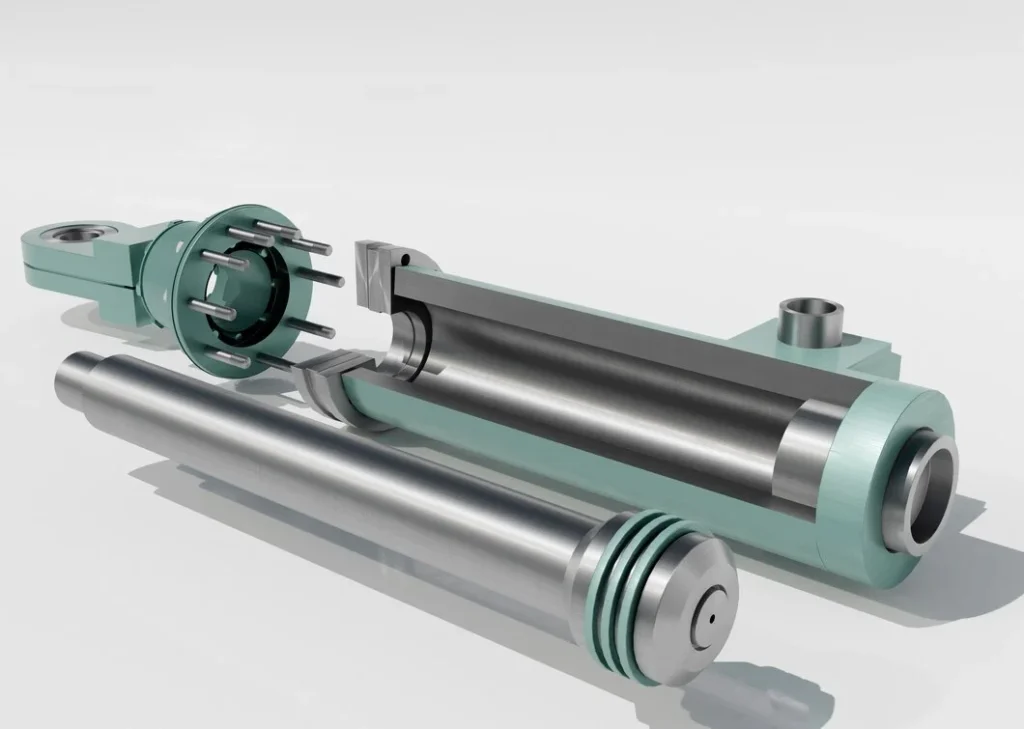
Upon issuing an extension command, the control valve directs hydraulic oil from the pump into the extension port, which then enters the extension chamber inside the main cylinder. As the oil pushes against the load, pressure builds up; this pressure acts on the internal pressure-bearing surface, generating a force that drives the sleeve. The pump must continuously replenish the oil to fill the increased chamber volume created by the extending sleeve, thereby allowing the movement to continue. The oil port is not necessarily located directly at the bottom of the main cylinder barrel. In some designs, oil is delivered to the bottom of the cylinder via internal oil lines; for double-acting telescopic cylinders, the oil chamber on the opposite side must also have an unobstructed return passage, otherwise extension may be impeded.
The Largest-Diameter Stage Extends First
The moving stage with the largest diameter—that is, the sleeve capable of moving relative to the outer cylinder barrel—typically extends first, carrying the smaller stages nested within it. At this point, although the smaller stages move outwards as part of the assembly, they have not yet extended relative to their respective outer sleeves.
The reason for this is that the largest moving stage usually has the greatest effective pressurised area—that is, the area used to generate axial thrust—and therefore requires lower pressure to overcome comparable loads. However, the sequence is also influenced by friction, load and internal structure; it should not be assumed that fluid enters only the largest stage whilst the other stages remain completely unpressurised.
Smaller Stages Extend in Sequence
Once the largest active stage has completed its stroke, it ceases relative movement whilst the pump continues to supply fluid. When the pressure is sufficient to overcome the load and friction of the next stage, that stage begins to extend, and the process is repeated in sequence. Common designs supply fluid via internally connected oil chambers, eliminating the need for the operator to switch the control valve each time a stage extends.
Upon switching to a smaller stage, the speed and thrust typically change: at the same flow rate, the smaller the effective area, the faster the extension speed; at the same pressure, the thrust is lower. For example, merely to illustrate the principle, if the effective area is halved—ignoring leakage, friction and back pressure—the speed will double, whilst the thrust at the same pressure will be halved. Therefore, you should have the supplier verify the load requirements for each stage individually; you cannot simply judge whether the entire cylinder is sufficient based on the thrust of the largest stage alone.
Internal Stops Limit Each Stage
Internal stops are mechanical structures that prevent the sleeve from exceeding its designed extension position, such as stop rings or shoulders. They limit the stroke of each stage, prevent over-extension, and work in conjunction with the design to maintain the necessary sleeve overlap length. Only after the preceding stage has reached its stop can the subsequent stage continue to extend as intended.
Stops are not the same as cushioning devices, nor do they necessarily automatically cut off the oil supply. Once all stages are fully extended, the extension command should be stopped in accordance with the equipment’s operating requirements to avoid prolonged oil supply whilst the cylinder is at the end of its stroke. If a cylinder that should extend sequentially exhibits skipping of stages, noticeable impact or prolonged pauses, the load, oil supply and causes of jamming should be checked; do not force the stroke to completion by increasing the pressure.
How Does a Telescopic Cylinder Retract?
A telescopic cylinder retracts under the influence of gravity, an external mechanical force or hydraulic driving force, whilst simultaneously draining the hydraulic fluid from the extension chamber back into the reservoir. The sleeve can only retract normally if there is sufficient retraction force and the return flow path is unobstructed; merely stopping the oil supply does not mean that the cylinder will retract automatically.
Gravity or External Load Retracts a Single-Acting Cylinder
A single-acting telescopic cylinder is typically extended by hydraulic force and retracted by gravity or an external force. For example, when a tipper lorry is lowered, the control valve opens the return line, allowing the body’s own weight to push the sleeve back and drain the hydraulic fluid. The hydraulic pump does not ‘suck’ the cylinder back.
This method is suitable for mechanisms where sufficient external force is available throughout the entire return stroke. If the cylinder is mounted horizontally and there is no mechanical return force, or if the return force is insufficient as the mechanism nears the retracted position, the cylinder may stop partway. You should ask the supplier to verify the minimum return force required over the full stroke to ensure it can overcome seal friction, mechanical resistance and return flow resistance.
Hydraulic Pressure Retracts a Double-Acting Cylinder
Double-acting telescopic cylinders utilise hydraulic power for both extension and retraction. During retraction, the control valve supplies fluid to the retract chamber; the hydraulic pressure generates a force that closes the sleeve, whilst simultaneously connecting the extension chamber to the return line. This is suitable for equipment lacking reliable gravity-assisted retraction and requiring active retraction of the load.
When selecting a cylinder, the retraction force must be verified separately. The effective pressure area on each side—that is, the area over which the hydraulic pressure acts to generate thrust or pull—is usually different; therefore, a high extension thrust does not necessarily imply an equally high retraction force. If the load is likely to accelerate the descent of the mechanism under its own weight, a suitable load control valve is also required; the double-acting design itself does not guarantee a stable descent speed.
Smaller Stages Typically Retract First
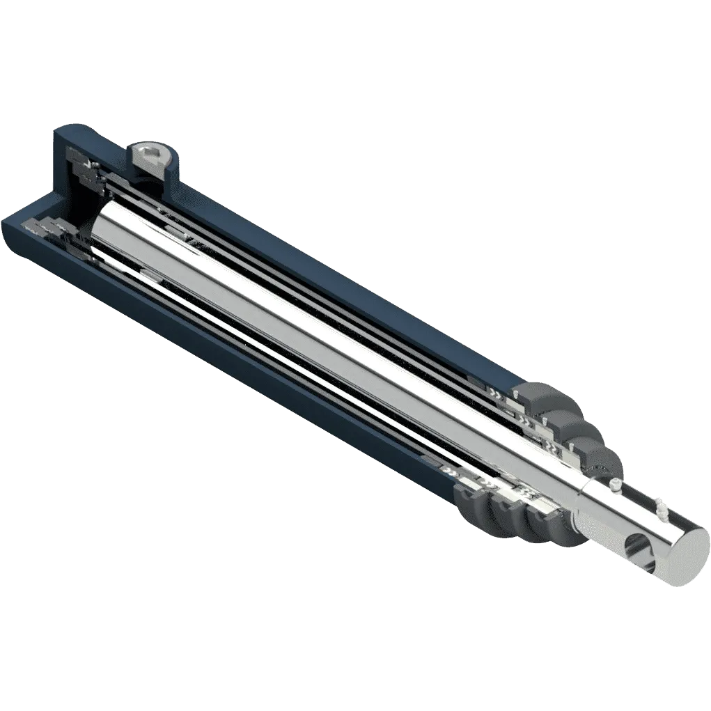
In common sequential designs, the smallest active stage typically retracts first, followed sequentially by the larger stages. You can think of this as first retracting the thinnest section into the adjacent sleeve, then retracting layer by layer. However, the actual sequence is influenced by the internal structure, load and friction; the manufacturer’s specifications for that particular model should be followed. If a cylinder that was previously functioning normally suddenly exhibits abnormal stage switching, noticeable judder or a stage becoming stuck, check for off-centre loading, mechanical jamming and return flow conditions.
Oil Returns Through Internal Passages and the System Valve
During retraction, the hydraulic fluid flows through the internal chambers and passages towards the return port, then returns to the reservoir via the system valve and piping. Single-acting cylinders typically use the same working port for both inlet and return; double-acting cylinders usually discharge fluid through the extension port during retraction. If the discharge is obstructed, back pressure—that is, the pressure preventing the fluid from being discharged— will build up, causing the return stroke to slow down or even stop.
The return flow rate of a double-acting telescopic cylinder may be significantly greater than the pump’s supply flow rate, as the effective areas on either side differ. When selecting valves, return lines and filters, their capacity should be verified against the maximum return flow rate specified by the manufacturer. If retraction is excessively slow, maintenance personnel should check for factors such as valve or line blockages and low oil temperature; do not loosen fittings to drain oil, as this may cause the load to drop suddenly.
Why Do Force and Speed Change Between Stages?
In common sequential telescopic cylinders, when switching to a smaller stage, the effective area under pressure decreases; consequently, the speed is higher at the same oil flow rate, whilst the thrust available at the same pressure is lower. However, as the actual pressure varies with the load, a ‘reduction in thrust capacity after switching stages’ does not necessarily mean that the force actually applied to the load will decrease immediately.
Effective Area Decreases With Each Smaller Stage
The effective area is the area that generates axial thrust when hydraulic pressure is applied. When a telescopic cylinder switches from a larger stage to a smaller one, this area typically decreases step by step; consequently, higher pressure is required to move the same load, whilst less fluid is needed to travel the same distance. The effective area is determined by the internal piston, seals and oil chamber structure, and cannot be calculated directly from the outer diameter of the sleeve. When selecting a model, the manufacturer should be asked to provide the effective area and stroke for each stage; Special constant-speed or synchronous designs also cannot simply follow the principles of standard sequential telescopic cylinders.
Smaller Stages Move Faster at Constant Flow
Theoretical extension speed = flow rate into the current active stage ÷ effective area. Flow rate refers to the volume of hydraulic fluid delivered per unit of time. The smaller the area, the less fluid required for the sleeve to move a given distance; consequently, the same supply of fluid allows it to move faster.
To illustrate the principle, consider the following calculation: with a fluid flow rate of 30 L/min, when the effective area is reduced from 100 cm² to 50 cm², the theoretical speed increases from 50 mm/s to 100 mm/s. This is not product test data; actual speed is also affected by leakage, valves and pump output. If the equipment requires smooth, constant speed, the oil flow rate should be adjusted according to the area at each stage; it cannot be assumed that maintaining the valve opening will automatically maintain the speed.
Available Extension Force Decreases by Stage
Ignoring friction and return line back pressure, theoretical extension force = pressure × effective area. Using the areas mentioned above, at a pressure of 10 MPa, the theoretical forces are 100 kN and 50 kN respectively. As the area of a lower stage is halved, the thrust capacity at the same pressure is also halved.
If the load does not decrease, the system will need to increase the pressure to continue pushing. For example, if the cross-sectional area is halved whilst the required thrust remains constant, the required pressure would ideally double. If this exceeds the permissible range of the system or the hydraulic cylinder, movement may cease. Therefore, thrust and load requirements should be verified stage by stage; one must not rely solely on the maximum stage thrust, nor compensate for inadequate selection by raising the pressure relief valve setting.
Load and Tipping Geometry Change During Travel
For tipper lorries, the thrust required by the hydraulic cylinder depends not only on the weight of the tipper body and the material, but also on the lever arm, i.e. the vertical distance from the line of action of a force to the rear pivot point. As the tipper body is raised, both the lever arm for gravity and the lever arm for the cylinder’s thrust will change; as the material slides and is discharged, the weight and centre of gravity will also shift. Consequently, the cylinder thrust required to rotate the tipper body will not remain constant.
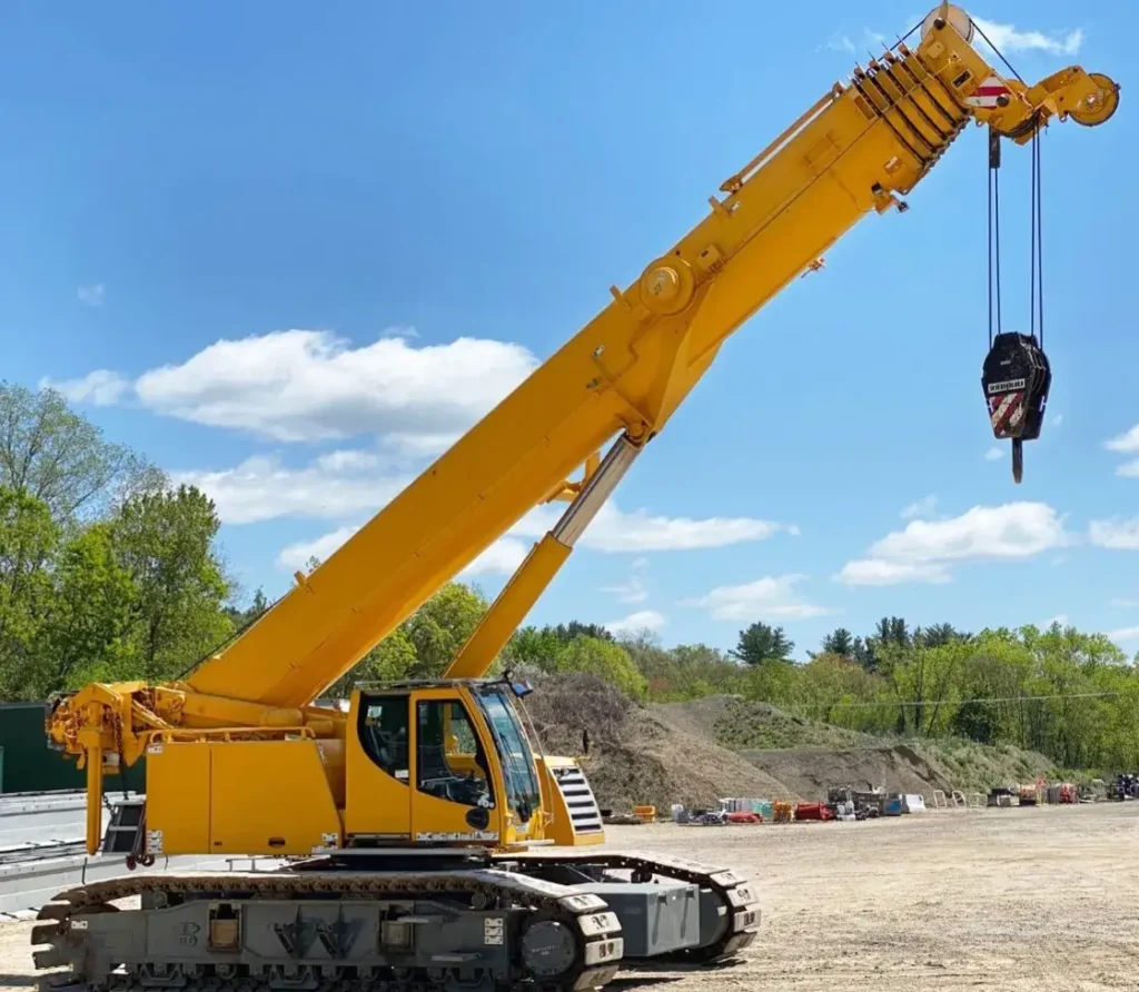
Many lifting mechanisms require greater thrust during the initial lifting phase, with the required thrust potentially decreasing thereafter; consequently, they are well-suited to a characteristic where the cylinder extends from a larger stage to a smaller one. However, one cannot assume that ‘the higher the lift, the lighter the load’: sticky or frozen material, or special installation geometries, may alter the requirements. Suppliers should be asked to verify the full stroke, particularly the thrust margin at each stage transition point, based on the actual installation point, centre of gravity and load, rather than calculating solely at the moment of lift initiation.
What Components Are Inside a Telescopic Cylinder?
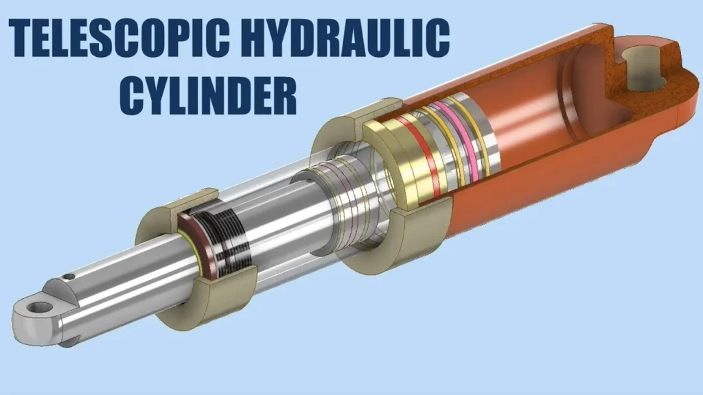
Telescopic hydraulic cylinders consist primarily of a main barrel, multi-stage moving sleeves, limiters, guides, seals and internal oil passages. These components are responsible for withstanding pressure, enabling movement, providing support and preventing leakage, respectively. The internal structures of single-acting and double-acting designs differ; please refer to the cross-sectional diagram of the specific model.
Main Barrel and Nested Moving Stages
The main barrel is the outermost pressure-bearing cylinder, whilst the moving stages are nested sleeves that can extend in stages. Larger moving stages both transmit thrust and accommodate smaller stages. When retracted, the stages are nested within one another; when extended, their strokes are cumulative, thereby achieving a longer travel distance within a shorter installation length.
Once all stages are fully extended, a certain overlap length must be maintained for guidance and support. When selecting a model, you should verify the retracted length, total stroke and load-bearing capacity of each stage; do not rely solely on ‘the number of stages’ or ‘the maximum extension length’. The surfaces of the sleeves should also be inspected for scratches or rust, as these surfaces are sealed and any damage may lead to oil leakage.
Stage Pistons, Stop Rings, and Bearings
Stage pistons or the load-bearing structures at the bottom of each stage are used to transmit hydraulic pressure, whilst stop rings limit the extension stroke. Guide bearings or guide rings support the sleeve and minimise misalignment. The bearings here are typically sliding supports and are not necessarily ball bearings. In different designs, the load-bearing, limiting and guiding functions may be performed by different components or combined structures.
Stop rings should not be used as buffers, nor should guide rings be used as supports for significant lateral forces. If the sleeve exhibits wear marks on one side or noticeable play, the wear of the guide components and the alignment of the installation should be checked, rather than simply replacing the seals. If damage to the stop components is discovered, use should be discontinued and repairs carried out in accordance with the manufacturer’s instructions.
Packing, Wipers and Piston Seals
Packing generally refers to sealing material or composite seals, such as multiple stacked V-rings, used to prevent hydraulic fluid from leaking out along the moving sleeve. A wiper is a dust seal responsible for scraping away dirt and debris from the surface of the retracted sleeve. The two serve different functions; a dust seal cannot replace a pressure seal.
Piston seals are used to separate oil chambers under different pressures and are particularly important in double-acting designs; some single-acting telescopic cylinders do not employ the same piston seal arrangement. When ordering a seal kit, provide the model number, serial number and corresponding grade, and confirm the applicable fluid and temperature ranges. Do not rely solely on the colour or appearance of old seals, nor should you treat the seal gland nuts of all models as adjustable components that can be tightened at will.
Ports and Internal Oil Passages
Port connections link to external piping, whilst internal oil passages, chambers or conduits are responsible for delivering fluid to the relevant pressurised areas and providing a route for fluid return. Single-acting cylinders typically use a single working port for both fluid supply and return; double-acting cylinders, however, require separate ports for fluid supply and return during extension and retraction. The position of the ports does not directly indicate the internal oil circuit. For example, certain double-acting telescopic cylinders deliver oil to the cylinder base via internal oil passages. When carrying out maintenance or connecting pipework, ports should be identified in accordance with the manufacturer’s circuit diagram; obstruction of internal passages may cause slow movement or abnormal pressure, and this must not be addressed by arbitrarily enlarging the oil orifices.
Mounting Clevises or Trunnions
Clevises are U-shaped mounting components connected to the equipment via pins, whilst trunnions are mounting structures that allow the hydraulic cylinder to pivot about an axis. They are typically located on the exterior of the cylinder; although not internal components, they are responsible for transmitting the cylinder’s thrust to the equipment and allowing the cylinder to change angle in accordance with the mechanism.
For example, when the body of a tipper lorry is raised, the angle of the hydraulic cylinder changes accordingly; the mounting connection must allow for the swing required by the design. When selecting a cylinder, verify the pin diameter, clevis spacing, trunnion dimensions and swing clearance; it is not sufficient merely to check that ‘the pin fits through’. A binding connection or misaligned axis will transmit lateral forces into the sleeve, accelerating wear on the internal guide components and seals.
Single-Acting vs. Double-Acting Telescopic Cylinders
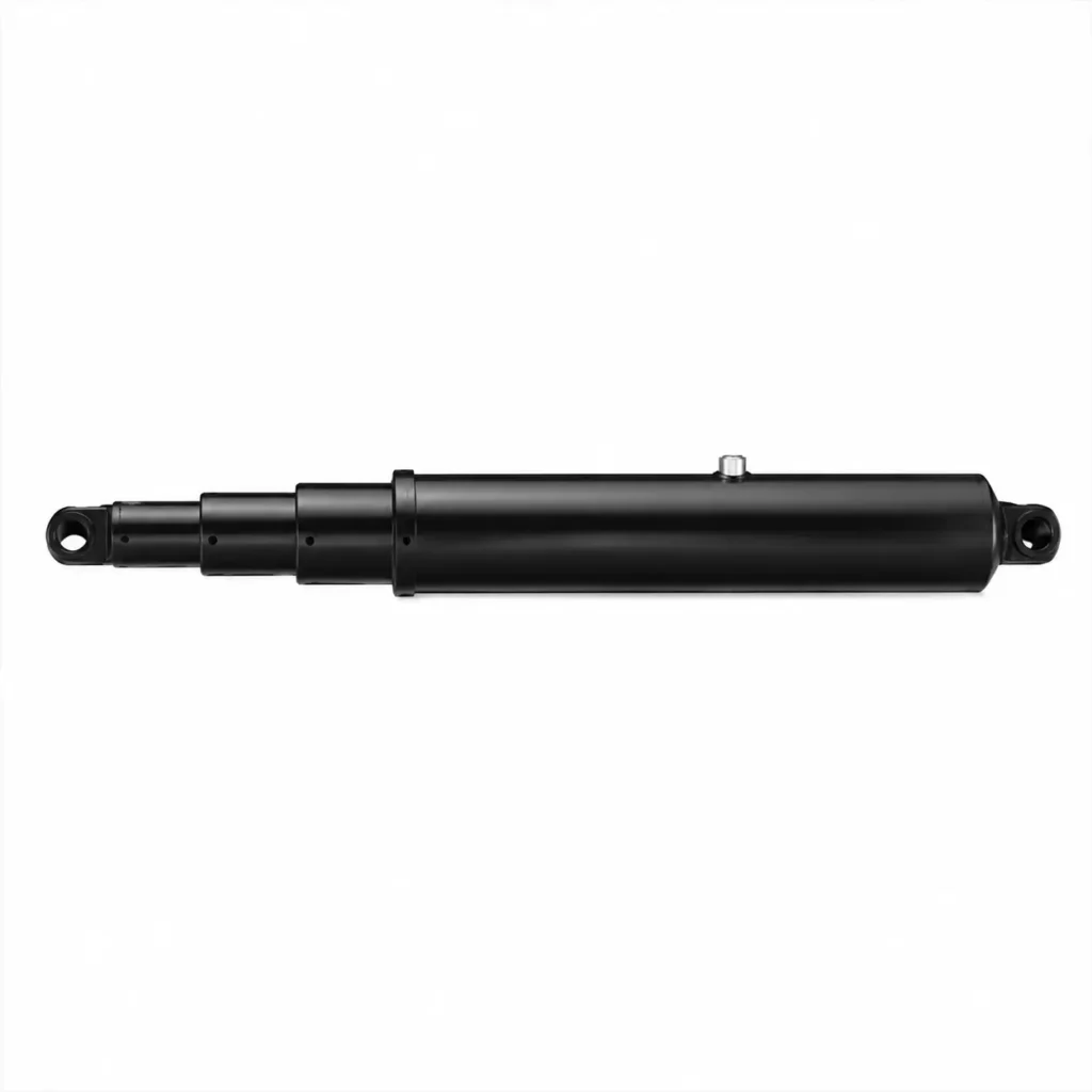
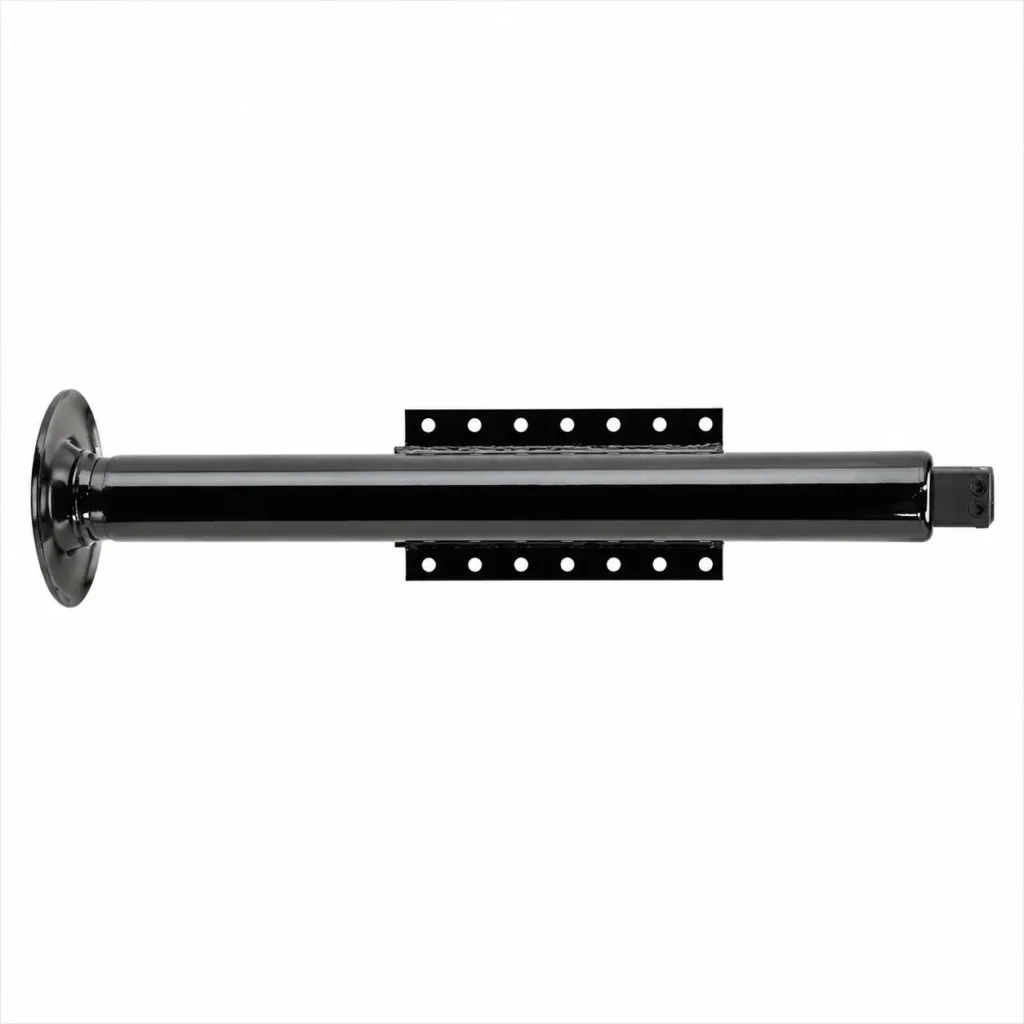
Where a reliable source of gravity or external force is available to complete the return stroke, a single-acting telescopic cylinder should be the preferred choice; where active hydraulic retraction of the load is required, a double-acting telescopic cylinder should be considered. The difference between the two lies not only in the number of hydraulic ports, but also in return flow capacity, load control and maintenance requirements.
① Retraction Method
Single-acting telescopic cylinders are typically extended by hydraulic power and retracted by gravity or external mechanical force. For example, in a tipper lorry, once the return oil passage is opened, the weight of the body itself pushes the sleeve back. Double-acting telescopic cylinders, on the other hand, supply oil to the return chamber to generate a retracting force hydraulically, making them suitable for mechanisms where a reliable external force for retraction is lacking.
You must first confirm whether there is still sufficient retraction force at the most unfavourable position throughout the entire retraction stroke. If the mechanism cannot overcome friction and return flow resistance as it nears the closed position, a single-acting cylinder may come to a standstill. When selecting a double-acting cylinder, the retraction force must also be verified separately; the extension thrust must not be mistaken for retraction capacity.
② Circuit Complexity
Single-acting circuits typically supply and return oil through the same working port to control extension, holding and retraction. Double-acting circuits, on the other hand, require oil to be supplied alternately to the two working ports whilst allowing the other side to discharge; their internal oil circuits and sealing structures are usually more complex.
For double-acting telescopic cylinders, the return flow rate must also be specifically verified. As the effective pressure area—the area over which oil pressure is applied to generate axial force—differs on each side, the volume of oil discharged during retraction may be significantly greater than the volume pumped in. When selecting control valves, return lines and filters, suppliers should be asked to provide the maximum return flow rate and permissible back pressure; sizing should not be based solely on the pump’s flow rate.
③ Load Control and Orientation
Single-acting cylinders are suitable for configurations where the load can reliably drive the cylinder’s return stroke; however, this should not be simplistically interpreted as ‘suitable for vertical applications but unsuitable for horizontal ones’. The key factor is whether gravity or external mechanical forces can generate sufficient retraction force throughout the entire stroke. Double-acting cylinders allow for active return and are more suitable for applications such as horizontal pushing and pulling; however, the manufacturer’s permitted installation directions and support conditions must still be verified.
Double-acting does not equate to automatic anti-drop protection, nor does it guarantee a constant speed at all times. If the load is capable of causing the mechanism to descend under its own weight, both types of cylinder require appropriate measures for descent control and load holding, such as a balancing valve—a valve that helps limit the load’s uncontrolled acceleration. In horizontal installations, the cylinder’s own weight and off-centre loading must also be managed; hydraulic return cannot replace mechanical guidance.
④ Cost, Maintenance and Suitability for Application
When specifications and configurations are similar, single-acting cylinders typically offer a cost advantage due to their simpler circuit and internal structure; double-acting cylinders provide active return capability but generally involve additional hydraulic lines, seals and maintenance tasks. However, actual price, service life and maintenance complexity still depend on the specific design and cannot be determined solely by the type of action.
For tipping mechanisms that rely on the body’s own weight to lower, single-acting valves are often sufficient; for horizontal mechanisms requiring the load to be actively retracted, double-acting valves are generally more suitable. When procuring, verify retraction force, permissible mounting orientation, return oil requirements and the availability of seal kits. If a single-acting valve is already capable of performing the operation reliably, upgrading to a double-acting valve may not offer any benefits; conversely, if a reliable retraction force is lacking, one should not select a single-acting valve solely to reduce the purchase price.
Where Are Telescopic Hydraulic Cylinders Used?
Telescopic hydraulic cylinders are primarily used in equipment requiring a long stroke but with limited installation space when retracted, such as tipper lorries, refuse ejection mechanisms and certain lifting platforms. The stroke referred to here is the distance travelled by the cylinder from fully retracted to fully extended. Suitability for use also depends on the thrust levels at each stage, the retraction method and the load-bearing conditions.
Tipper Lorries and Tipper Trailers
Dump lorries and dump trailers are typical applications for telescopic cylinders. When the body is lowered, the cylinder must be retracted into a limited space; during unloading, a longer stroke is required to raise the front of the body. A multi-stage telescopic structure can accommodate both these requirements. A common configuration utilises single-acting telescopic cylinders, where hydraulic pressure is used for extension and the body’s own weight for retraction.
When selecting a cylinder, one must not base the choice solely on the load capacity in tonnes. You must also provide the body’s own weight, the centre of gravity of the load, the mounting points and the target lifting angle, so that the supplier can verify the thrust required throughout the entire stroke—particularly whether there is still sufficient margin when switching to a smaller stage. The cylinder must not be used as an anti-tilt strut; issues relating to off-centre loading and uneven ground must be addressed by the overall machine design and operating conditions.
Refuse and Material-Handling Equipment
Telescopic cylinders can be used in refuse collection vehicle push-out plates, transfer trailer unloading mechanisms, and certain compaction and material-handling equipment. These mechanisms require the push plate to travel long distances whilst minimising the space occupied by the cylinder when retracted. Custom Hoists’ application data for double-acting telescopic cylinders includes refuse compaction equipment and push-out trailers.
Horizontal pushing mechanisms typically lack a reliable gravity return, so double-acting telescopic cylinders, where both extension and retraction are hydraulically driven, are frequently used. You should verify the pushing force, retraction force and speeds at each stage separately, whilst ensuring the guide rails can withstand the lateral forces exerted by the push plate. If resistance to pushing remains significant during the latter half of the stroke, selection should not be based solely on the maximum pushing force.
Lifting Platforms and Mobile Machinery
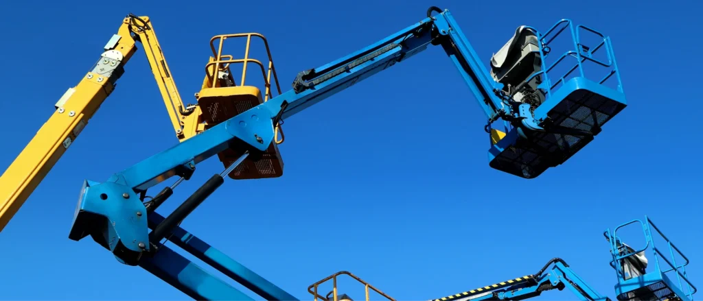
Some lifting platforms, lifting masts and mobile lifting mechanisms utilise telescopic cylinders to achieve a greater lifting stroke within a lower stowed height. However, the fact that a platform or boom is telescopic does not necessarily mean that multi-stage cylinders are used internally; some equipment employs standard cylinders in conjunction with chains, wire ropes or linkages.
In such applications, it is necessary to simultaneously verify motion smoothness, load holding capability and the guidance mechanism. Conventional sequential telescopic cylinders may vary in speed during stage changes and cannot be assumed to operate at a constant speed throughout the entire stroke. If the platform requires smooth lifting and lowering, the manufacturer should match the cylinder configuration to the control circuit; where personnel are carried, the equipment must also meet requirements for fall protection and emergency descent, and suitability cannot be determined solely on the basis of sufficient cylinder thrust.
Applications With Long Stroke and Limited Mounting Space
To determine whether a telescopic cylinder is required, one can first compare two dimensions: the required stroke and the permissible installation length when the cylinder is fully retracted. If a standard single-stage cylinder cannot satisfy both requirements simultaneously, a telescopic cylinder offers a clear spatial advantage. When requesting a quotation, it is advisable to mark these two dimensions on the installation drawing and specify the load, installation orientation and return mechanism. If there is ample installation space, or if the equipment places particular emphasis on constant-speed motion and ease of maintenance, a standard single-stage cylinder may be more suitable. More stages do not necessarily equate to better performance: increasing the number of stages adds more sealing and guiding components, and during selection, the thrust and stability at full extension must be verified for each stage.
What Causes Telescopic Cylinder Problems?
Faults in telescopic cylinders are usually associated with off-centre loading, contamination, abnormalities in the oil supply or return, or exceeding the design load, and are not necessarily due to seal failure. When troubleshooting, first record at which stage the anomaly occurred—whether during extension or retraction, whilst the cylinder is cold or hot, and whether it was under load. Before inspection or disassembly, the load must be securely supported, the power source isolated, and residual pressure released in accordance with the manufacturer’s procedures.
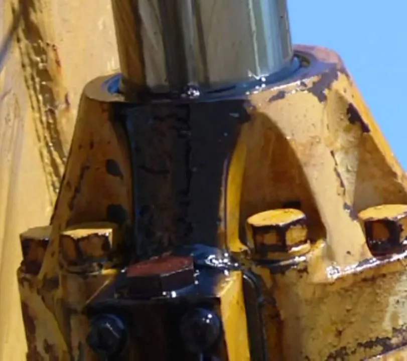
Side Load and Stage Misalignment
A side load is a force acting transversely on the hydraulic cylinder, causing the moving sleeve to deviate from its normal axis. Misalignment at the mounting points, binding of pin connections, wear on the push plate guide rails, or an eccentric load may all subject the sleeve to bending forces, resulting in uneven wear of the guide components, seal damage and movement binding.
For example, if the guide rails on a refuse lorry’s push-out panel become worn, the push-out panel may transmit lateral forces to the hydraulic cylinder. You should first inspect the mounting connections and external guides before assessing whether there is internal damage; simply replacing the seals will not usually eliminate recurring faults caused by off-centre loading.
Contamination and Seal Damage
Particles in the hydraulic fluid, as well as mud and sand entering as the sleeve retracts, can scratch the sliding surfaces and damage the seals. The dust seal is responsible for scraping away contaminants from the sleeve surface, whilst the pressure seal prevents hydraulic fluid leakage; failure of either component may accelerate wear. Incompatibility between the hydraulic fluid or temperature and the seal material will also shorten the service life. If persistent oil dripping is observed, the cylinder barrel for scratches, the dust seal and the cleanliness of the hydraulic fluid should all be inspected simultaneously; simply replacing the seal kit is insufficient. A thin lubricating oil film does not necessarily indicate a fault; some models permit a thin oil film on the surface, so judgement should be based on the manufacturer’s criteria. Furthermore, do not blindly tighten the seal gland to stop leaks, as excessive tightness may increase friction and affect stage sequencing.
Incomplete or Jerky Stage Sequencing
Stage sequencing is the process whereby, after an active stage reaches the end of its stroke, the next stage continues the movement. In standard sequential telescopic cylinders, the speed may naturally increase when switching to a smaller stage; however, noticeable jerking, impact, abnormal sequencing or persistent pauses require further investigation. Possible causes include air ingress, unstable oil supply, abnormal seal friction, off-centre loading or sleeve deformation. You should record ‘which stage, at what position, and under what load the anomaly occurred’ and provide this information to maintenance personnel so they can assess the situation in conjunction with pressure and flow rate data. For example, if the cylinder stops only when extending under load at a lower stage, this may be related to insufficient thrust at that stage and should not be directly attributed to a faulty oil pump. Bleeding should be carried out in accordance with the procedure for that model; do not loosen fittings arbitrarily, nor attempt to force the stroke by increasing the pressure.
Insufficient Return Load or Restricted Flow
Single-acting telescopic cylinders typically retract under the influence of gravity or external mechanical force. If the return force provided by the carriage or mechanism is insufficient to overcome friction and return flow resistance, the cylinder may fail to retract even if the valve is open. Although double-acting telescopic cylinders utilise hydraulic return, they may still be affected by insufficient oil supply, restricted return flow, or control valves failing to open properly.
When troubleshooting, check the return force, whether the quick-connect couplings are correctly engaged, the condition of the valves, filter and line resistance, and whether the oil temperature is too low. The return flow rate for double-acting telescopic cylinders may exceed the supply flow rate; therefore, valves and return lines should be selected according to the maximum return flow requirement specified by the manufacturer. Do not accelerate the descent by releasing oil through the lines, as this may cause the load to drop suddenly.
Overextension and Rod Buckling
Overextension occurs when the moving stage exceeds the design-permitted position; buckling refers to the unstable bending of a slender sleeve or end-stage piston under pressure. Overextension may be caused by damaged limiters, incorrect assembly or forced extension by an external mechanism. Long strokes, excessive thrust and poor support increase the risk of buckling. These are not the same type of fault, nor can they be resolved simply by reducing the speed of movement. When selecting a model, the manufacturer should be asked to verify stability based on the maximum extension length, mounting method and maximum compressive load; safety should not be judged solely on the basis that ‘the pressure has not exceeded the rated value’. If bending, localised bulging or abnormal stop positions are detected, use should be discontinued and the cylinder referred to a professional for assessment; do not attempt to straighten it on site and resume operation.
What Should Engineers Specify Before Buying?
Before purchasing a telescopic hydraulic cylinder, the installation dimensions, full-stroke load, requirements for each stage of movement, return mechanism and acceptance criteria must be clearly defined. Simply providing details such as ‘number of stages, tonnage and stroke length’ is insufficient to confirm whether the cylinder is suitable. It is best to provide an installation drawing and an operating conditions table so that the supplier can confirm each item individually.
Total Stroke, Closed Length and Number of Stages
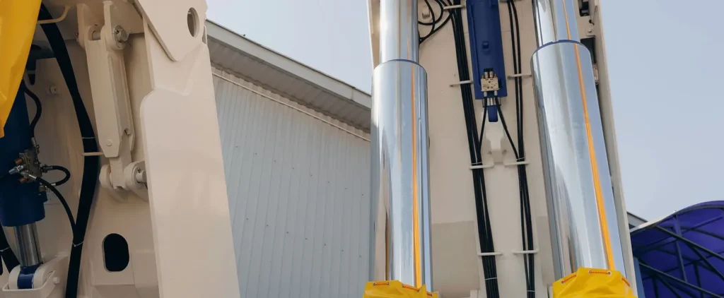
The total stroke is the sum of the relative extension distances of each moving stage; the closed length is the specified measurement when the cylinder is fully retracted. The drawing should clearly specify the measurement reference, such as the centre-to-centre distance between the end pin holes, and should indicate the permissible closed length, total stroke and maximum external dimensions separately, to prevent the supplier from interpreting the installation length as the overall length.
The number of stages should be determined jointly based on available space, load-bearing capacity at each stage and stability; there is no need to seek a higher number of stages in advance. If there is no specific structure that must be adhered to, dimensional constraints may be provided first, allowing the supplier to propose solutions. A higher number of stages typically implies more sealing and guiding components, but does not necessarily result in greater thrust.
Stage-by-Stage Force and Speed
Require the manufacturer to list the stroke, effective pressure area (the area over which hydraulic pressure is applied to generate axial force), available thrust and expected speed for each stage. When a standard sequential telescopic cylinder is scaled down to a smaller stage, the thrust capacity at the same pressure typically decreases, whilst the speed at the same flow rate typically increases.
For example, with a supply flow rate of 30 L/min and a pressure of 10 MPa, a moving stage with an effective area of 100 cm² has a theoretical thrust of 100 kN and a speed of 50 mm/s; when the area is reduced to 50 cm², the theoretical thrust drops to 50 kN and the speed increases to 100 mm/s. If the equipment still requires 70 kN of thrust at this point, the smaller stage will be insufficient at that pressure. Actual selection must also take into account friction, back pressure and leakage; one cannot rely solely on the parameters of the largest stage.
Working Pressure and Maximum Load Geometry
The normal working pressure, system pressure relief setting, anticipated pressure peaks and operating frequency should be specified separately. Load data must also include weight, centre of gravity and mounting point locations, as the same weight may require different cylinder thrusts in different mechanisms.
For example, two tipper lorries carrying the same load may require significantly different lifting thrusts due to differences in cylinder mounting points and the body’s centre of gravity. You should provide the rear pivot point, the mounting points at both ends of the cylinder, the body’s dead weight, the centre of gravity of the material, and the target lifting angle, so that the manufacturer can verify the full stroke, particularly at the transition points. For wet or sticky materials, you must also specify that they may adhere to the body; it cannot be assumed that the load will discharge smoothly during the lifting process.
Mounting Orientation and Allowable Side Load
Specify whether the hydraulic cylinder is to be mounted vertically, horizontally, at an angle or upside down, and whether it will swing during operation. Drawings should include dimensions for pin holes, fork lugs or trunnions, the range of swing and the positions of external guides; it is not sufficient merely to confirm that ‘the interface fits’.
A lateral load is a force acting transversely on the sleeve, which may cause uneven wear, jamming and bending. If they cannot be entirely avoided, their magnitude, direction and point of application must be specified so that the manufacturer can confirm the permissible limits. For long-stroke compression applications, buckling must also be verified at maximum extension length; that is, the risk of slender sleeves buckling and bending under compression. Rated oil pressure must not be used as a substitute for this check.
Single- or Double-Acting Retraction
Single-acting cylinders typically retract under the action of gravity or external mechanical force, whilst double-acting cylinders utilise hydraulic power for active retraction. **When selecting a single-acting cylinder, ensure that sufficient external force is available throughout the entire return stroke; when selecting a double-acting cylinder, the retraction force, return stroke time and return flow requirements should be specified separately. For example, a tipper body can be lowered by its own weight, so a single-acting cylinder is usually suitable; a horizontal push mechanism without springs or other mechanical return forces typically requires a double-acting cylinder. When a double-acting cylinder retracts, the return flow rate may exceed the pump’s supply flow rate; therefore, the manufacturer should be asked to provide the maximum return flow rate and permissible back pressure—that is, the pressure when the return flow is obstructed—so that valves, pipework and filters can be selected accordingly.
Seals, Surface Finish, Testing and Documentation
Provide the brand and model of the hydraulic fluid, the minimum start-up temperature, the maximum oil temperature, and environmental conditions such as dust and salt spray. The manufacturer must confirm the sealing materials, surface treatment of the moving sleeve and dust protection configuration based on this information. Surface roughness is a quantitative measure of minute surface irregularities; it must be compatible with the sealing system, and it is not acceptable to make a general requirement such as ‘the smoother the better’ or to specify only the name of a coating.
At the time of acceptance, arrangements should be made for dimensional checks, pressure and leakage tests, full-stroke operation, and sequence checks, with test conditions and acceptance criteria clearly documented. If ISO 10100 is adopted, the version and applicable clauses must be specified; this standard covers the acceptance and functional testing of hydraulic cylinders. The handover documentation must include, at a minimum, approval drawings, test records corresponding to serial numbers, installation and maintenance instructions, and seal part numbers, to prevent a lack of traceability during subsequent handover, maintenance, or ordering of spare parts.
Frequently Asked Questions About Telescopic Hydraulic Cylinders
Which Telescopic Stage Extends First?
In a typical sequential telescopic cylinder, the moving stage with the largest diameter usually extends first, carrying the smaller inner stage with it; once the limit stop is reached, the next smaller stage then extends in turn. The largest moving stage typically has the greatest effective compression area, so the pressure required to overcome a comparable load is lower. However, specialised synchronous or sequential control designs may differ, so you should refer to the manufacturer’s specifications for the specific model.
Why Does a Telescopic Cylinder Speed Up as It Extends?
When the oil flow rate remains constant, switching to a smaller stage typically increases the extension speed. This is because the effective area decreases, requiring less oil to move the same distance. Ideally, when the effective area is halved, the speed doubles; this represents a change in speed following the stage change, rather than continuous acceleration throughout the entire extension process. If you require a near-constant speed, you should ask the supplier to match the oil flow rates across the stages or adopt a suitable cylinder design.
Can a Telescopic Cylinder Operate Horizontally?
Yes, but you must select a model suitable for horizontal installation and verify the support and return conditions. When installed horizontally, the weight of the sleeve and load eccentricity increase the forces on the guide components; you will need to ensure that the external guide rails bear the weight of the moving parts and the lateral forces. In the absence of a reliable mechanical return force, a double-acting design with hydraulic active retraction should generally be considered; a single-acting cylinder will not retract on its own simply by cutting off the oil supply. Even a double-acting design cannot replace guidance and bending stability checks.
Can a Telescopic Hydraulic Cylinder Be Repaired?
Many telescopic cylinders can be repaired, but this depends on the extent of the damage and the availability of spare parts. Seals, dust seals and guide components can usually be replaced; however, if the sleeve is bent, bulged, deeply scratched or the stop components are damaged, a professional assessment is required – it is not sufficient to simply replace the seals and continue using the cylinder. You should first provide the model number, serial number and location of the fault so that the manufacturer can confirm the repair plan and required parts. Before disassembly and repair, the load must be securely supported and any residual pressure released; if the oil leak is caused by off-centre loading or contamination, the underlying cause must also be rectified.
Choosing a Trusted Hydraulic Cylinder Manufacturer
From standard hydraulic cylinders to custom solutions, we help you improve equipment performance, delivery reliability, and batch consistency
Explore Rivmate Cases

Hey There, I'm Melody!
We are a hydraulic cylinder manufacturer. For over 20 years, we have focused on producing reliable hydraulic cylinders. Need a hydraulic cylinder solution? Feel free to contact us.