Home / Types of Double Acting Hydraulic Cylinders and How to Choose
Types of Double Acting Hydraulic Cylinders and How to Choose
- Author: GY Hydraulic
- 20+ Years of Manufacturing
Double-acting hydraulic cylinders are driven by hydraulic fluid to extend and retract. Common types can be categorized in two ways: by piston rod configuration—single-rod and double-rod, referring to piston rods extending from one end or both ends of the cylinder, respectively—and by cylinder body structure—tie-rod type and welded type, referring to connections made via external tie rods or welding between the main cylinder components, respectively. These classifications can be combined; for example, a single hydraulic cylinder can be both single-rod and tie-rod type.
When selecting a model, you should first determine the required thrust and pulling force, as well as the travel distance (stroke), and then choose the appropriate structure based on system pressure, installation space, operating speed, and operating environment. It is particularly important to note that for standard single-rod, double-acting hydraulic cylinders, under identical supply pressure and assuming no return line back pressure or friction, the retracting pulling force is less than the extending thrust; therefore, calculations must be performed for both directions. Below, you will learn about the characteristics of different types and how to gradually narrow down your options based on your specific application.
Table of Contents
What Are the Main Types of Double Acting Hydraulic Cylinders?
Based on piston rod configuration and internal operating mechanisms, double-acting hydraulic cylinders can be classified into single-rod differential, double-rod, series, and double-acting telescopic types. You can start by understanding their key differences: single-rod cylinders are suitable for general push-and-pull motions; equal-diameter double-rod cylinders facilitate consistent bidirectional output; series cylinders are used to increase output force when diameter is limited; and telescopic cylinders are used to achieve a long stroke within a compact retracted space.
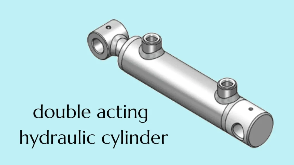
① Single-Rod Differential Cylinders
In a single-rod differential hydraulic cylinder, the piston rod extends from only one end. The effective areas on either side of the piston that bear the hydraulic pressure differ: the rodless side has the full piston area, while the rod side must account for the area occupied by the piston rod. Therefore, at the same supply pressure—and ignoring return back pressure and friction—the extension thrust is greater than the retraction pull; at the same input flow rate, the retraction speed is faster than the extension speed. The term “differential” here describes the difference in area between the two sides and does not imply that you must use a special differential circuit.
If your equipment needs to push material forward, clamp a workpiece, and then actively retract to return to its home position, this configuration is typically the first option to evaluate. However, if the cylinder must also pull a heavy load during retraction, you cannot rely solely on the thrust rating listed in the product specifications. If the same force and speed are required in both directions, a single-rod design can still meet the requirements through proper selection and control, but the forces and speeds for each direction must be calculated separately.
A practical verification method is to confirm the bore diameter, rod diameter, and the corresponding thrust and pull forces at a given pressure with the supplier. For example, assuming a bore diameter of 80 mm and a rod diameter of 40 mm, the effective area on the rod side is only 75% of that on the non-rod side based on area calculations. Therefore, under the ideal conditions described above, the retraction pull force would also be only 75% of the extension thrust. This is a theoretical calculation example; actual output must also account for friction and return oil back pressure.
② Double-Rod or Balanced Cylinders
In a double-rod hydraulic cylinder, rods extend from both sides of the piston. When the rod diameters on both sides are the same, the effective pressure-receiving areas on both sides are equal; this is what is referred to here as a “balanced” design. Under the same effective pressure differential, the theoretical output force in both directions is the same; under the same input flow rate, the theoretical movement speed in both directions is also the same. A double-rod design does not automatically mean it is balanced; you must verify that the rod diameters at both ends are consistent.
If you want a reciprocating worktable to have similar driving force and speed when moving left and right, this configuration is worth considering. However, “balanced” does not mean the hydraulic cylinder will automatically maintain precise positioning; actual speed and positioning performance still depend on the load, control valves, and whether position detection and feedback control are configured.
When selecting a model, you need to check the installation drawing to verify the clearance for the piston rods at both ends throughout the entire stroke and allow for protective clearance. If the rear of the equipment is flush against the machine frame and there is no space to accommodate the extended rod at the other end, a double-rod design is generally not suitable. Additionally, under conditions where the cylinder bore and supply pressure are the same, the unidirectional output force of an equal-diameter double-rod design is lower than the thrust on the rodless side of a single-rod design; therefore, it cannot be directly substituted based solely on the original cylinder bore.
③ Tandem Cylinders
In a tandem hydraulic cylinder, two or more pistons are arranged along the same axis and move together via a common piston rod or mechanical connection. When pressure is applied simultaneously to the corresponding working chambers and each piston exerts force in the same direction, the output forces can be combined. You can think of it as “multiple pistons working together to push a single output rod.” This configuration primarily increases force rather than adding the strokes of each piston together.
If your press-fitting or clamping mechanism requires greater force, but equipment width limits the cylinder bore diameter and increasing pressure is not a viable option for the system, you may want to consider a tandem configuration. However, it typically requires a longer axial installation space and increases the complexity of seals and fluid circuits. If equipment length is also limited, or if a standard single cylinder already meets the requirements, the advantages of a tandem configuration are not significant.
Do not simply double the rated thrust just because there are two pistons. You should have the supplier confirm which working chambers are contributing to the force, the effective area of each chamber, and the supply pressure, and then calculate the resultant force. You should also check the pump’s flow rate: when multiple working chambers are filled with oil simultaneously, a higher total flow rate is usually required to maintain the original motion speed. The term “series” here refers to a mechanical combination and should not be simply understood as connecting the ports of two standard hydraulic cylinders in series.
④ Double-Acting Telescopic Cylinders
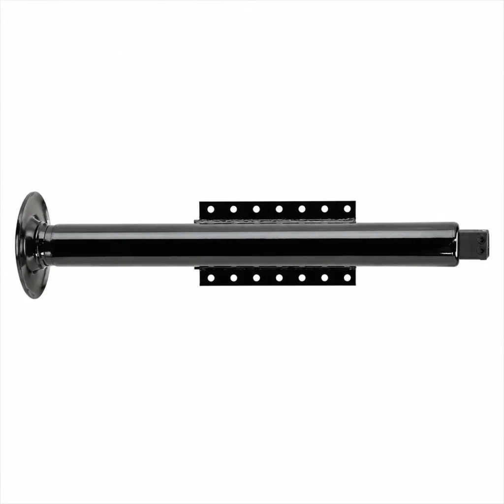
Double-acting telescopic hydraulic cylinders consist of multiple stages of nested tubes, similar to a telescoping pipe that extends section by section; both extension and retraction are driven by hydraulic fluid. Their primary advantage is that they are short when retracted yet provide a long stroke—that is, a long travel distance. Conventional telescopic designs typically have the larger stages extend first and the smaller stages retract first, but you should always refer to the internal structure and operating instructions of the specific model.
If your material-feeding mechanism requires a long extension, but the equipment can only accommodate a shorter hydraulic cylinder, and the return stroke cannot be reliably achieved by gravity, you may want to consider this design. However, in standard sequential telescoping cylinders, the effective pressure area changes when switching between stages; therefore, the output force and speed may also vary when the supply pressure and flow rate remain constant. If you require a constant speed throughout the entire stroke or precise positioning, you will need to further evaluate specialized designs and control solutions.
When selecting a model, in addition to the total stroke and retracted length, you must also request from the supplier the extension thrust, retraction pull force, operating sequence, and flow rate requirements for each stage; the thrust of the highest stage cannot be used to represent the capacity of the entire stroke. You also need to check whether the load has independent guidance to prevent the extended sleeve from being subjected to significant lateral thrust; the return oil passage must also meet the requirements, otherwise abnormal back pressure may occur or the normal operation of each stage may be affected.
How Do Construction Styles Differ?
The structural design of a double-acting hydraulic cylinder primarily affects how the cylinder body is connected, the amount of space it occupies during installation, and how it is disassembled and maintained later on. Note that these terms are not entirely mutually exclusive: “Mill-Type” emphasizes a design suited for heavy-duty industrial applications, which may also incorporate welded structures; meanwhile, custom hydraulic cylinders can be modified based on structures such as tie-rod or welded designs. When selecting a model, you should compare the load capacity, mounting dimensions, and maintenance methods of specific models; performance should not be judged solely based on the structural designation.
Tie-Rod Cylinders
Tie-rod hydraulic cylinders use high-strength, long tie rods on the exterior of the cylinder barrel to clamp the end caps to the barrel. Here, the “tie rod” refers to the connecting component that secures the cylinder body, as opposed to the piston rod, which extends from the cylinder body to push the load. This removable design facilitates the inspection and repair of internal components; therefore, if ease of maintenance and spare part replacement are priorities, you should prioritize tie-rod cylinders. They are commonly used in machine tools, fixtures, and factory production equipment.
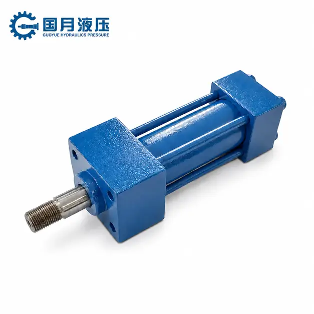
For example, if your production line clamping mechanism requires long-term repetitive operation and you need to replace seals or inspect the cylinder barrel during maintenance, tie-rod cylinders are typically worth considering. However, the external tie rods and end caps also take up space. If the hydraulic cylinder must be installed in a confined space, you need to verify the full external dimensions—not just the cylinder bore diameter. Tie-rod-type cylinders are also not limited to light loads or low pressures; refer to the model specifications for specific load-bearing capacity.
When purchasing or replacing a cylinder, it is recommended to verify the mounting hole spacing, retracted length, rod-end threads, and port locations. Even if the cylinder bore and stroke are identical, this does not mean that two hydraulic cylinders are directly interchangeable. When reassembling after repair, you must tighten the rod nuts according to the manufacturer’s specified sequence and torque; do not tighten them arbitrarily based on feel.
Welded-Body Cylinders
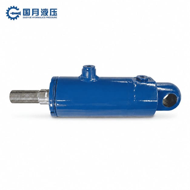
Welded-body hydraulic cylinders typically have the cylinder barrel and other major components, such as the cylinder base, welded together; they do not rely on long rods passing through the exterior of the cylinder body for support. This design allows for a more compact form factor and facilitates the arrangement of mounting brackets and hydraulic ports in accordance with equipment layout. However, a welded-body design does not mean the entire hydraulic cylinder is permanently welded shut and cannot be repaired; many models feature removable threaded or other types of front-end guide seal assemblies, allowing the piston rod assembly to be removed and seals to be replaced.
If you are designing a push-pull mechanism for mobile equipment that requires the hydraulic cylinder to clear the frame, linkages, or other components, the welded type can be a key option to consider. However, the degree of compactness depends on the specific design; not all welded cylinders are smaller than all rod-type cylinders. If your maintenance plan requires the separate replacement of major components such as the cylinder base or cylinder barrel, welded connections may also increase the difficulty of repairs.
Mill-Type Cylinders
“Mill-Type” typically refers to rugged hydraulic cylinders designed for heavy-duty industrial applications, commonly found in equipment such as metallurgical and heavy machinery. This design emphasizes the load-bearing capacity of the cylinder body, end caps, connection points, and guide supports. Common configurations include bolted flange connections, as well as welded designs. A flange can be simply understood as a thickened rim intended for bolted connections; therefore, “Mill-Type” does not refer to a single, fixed connection method.
If your equipment is subjected to high loads over extended periods, experiences frequent starts and stops, or is exposed to significant shock during operation, it is worth evaluating this design. For example, heavy-duty press-fitting mechanisms not only require sufficient thrust but also need hydraulic cylinder connections capable of withstanding repeated loading. However, for equipment operating under light loads, in compact spaces, or where the overall weight of the machine is restricted, a heavy-duty design may increase volume, weight, and procurement costs, and may not be the most suitable option.
When determining whether a Mill-Type design is necessary, you should provide information on normal load, peak load, operating frequency, and the presence of impact forces—not just the operating pressure. “Heavy-duty” does not mean that the piston rod can freely withstand lateral forces—that is, forces that push and bend the piston rod from the side. If the direction of the load movement may deviate from the hydraulic cylinder’s axis, you must still verify proper alignment and independent guidance; for long-stroke thrust applications, you must also calculate whether the piston rod is susceptible to bending under compression.
Custom and Special-Purpose Cylinders
Custom and special-purpose hydraulic cylinders are products whose dimensions, mounting methods, materials, seals, or functions are tailored to specific tasks; they do not represent a distinct cylinder mounting configuration. For example, you can incorporate position sensors into rod-type or welded hydraulic cylinders to detect the piston’s position; you can also adjust the seals and materials to accommodate special hydraulic fluids, low-temperature environments, or corrosive conditions.
Customization is truly valuable when standard models cannot meet specific installation or performance requirements. For instance, if the installation clearance of legacy equipment cannot be altered but existing standard cylinders do not fit, you may consider customizing the mounting dimensions. If the only differences are in stroke length or port orientation, you should first inquire whether the standard series supports configuration adjustments—this is typically more straightforward than a complete redesign. Manufacturers may also be able to meet your needs by modifying existing modules.
When submitting customization requests to suppliers, it is recommended that you provide installation drawings, push-pull loads, stroke, speed, operating pressure, hydraulic fluid type, and temperature range, while clearly specifying the acceptance criteria. For example, simply stating “precise positioning is required” is insufficient; you should specify the allowable positional error, load conditions, and whether the cylinder is required to repeatedly stop at the same position. You should also confirm the supply arrangements for seal kits and critical spare parts to avoid a situation where the initial installation is resolved but subsequent maintenance becomes difficult.
Single-Rod vs. Double-Rod: Which Layout Fits the Motion?
If your equipment primarily performs heavy-duty work in one direction with a lighter load during return travel, a single-rod hydraulic cylinder is usually the preferred choice. If you want similar output force and speed in both directions and can provide sufficient space for the piston rods to extend on both sides, then choose a double-rod configuration. In the comparison below, “double-rod” refers to a design where the piston rods on both sides have the same diameter; if the rod diameters differ, the performance on each side will also differ.
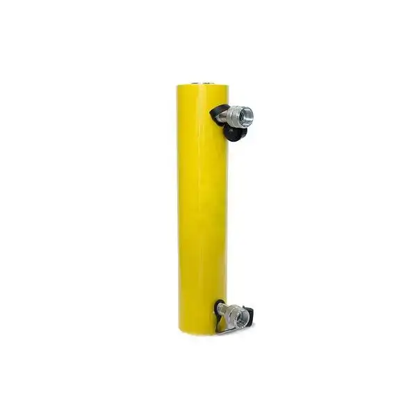
a. Extension and Retraction Force
The output force of a hydraulic cylinder depends on the oil pressure and the effective pressure area—that is, the area where the oil pressure actually acts and is capable of pushing the piston. In a single-rod design, the full piston area is utilized during extension, while the area occupied by the piston rod must be subtracted during retraction. Therefore, under the same supply pressure—and ignoring return line back pressure and friction—the extension thrust is greater than the retraction pull force. In a double-rod design with equal rod diameters, the effective areas on both sides are the same; under the same pressure differential, the theoretical output force in both directions is identical.
For example, assume a cylinder bore of 80 mm, a rod diameter of 40 mm, and a supply pressure of 10 MPa. Calculating according to “Force = Pressure × Effective Area,” the theoretical extension thrust of a single-rod cylinder is approximately 50.3 kN, while the retraction pull force is approximately 37.7 kN; for a double-rod cylinder with the same bore and a rod diameter of 40 mm on both sides, the theoretical output force in both directions is approximately 37.7 kN. This example illustrates that the double-rod design provides more symmetrical output in both directions but does not automatically deliver greater force for the same cylinder bore.
If your mechanism performs a forward press-fit operation and only needs to return the fixture during retraction, the force characteristics of a single-rod design are often more suitable. If you need to push heavy loads in both directions, you must calculate the thrust and tensile force separately; you cannot rely solely on the maximum thrust specified in the product data. It is especially important to note that increasing the diameter of the piston rod while keeping the cylinder bore constant reduces the effective area on the rod side, thereby lowering the theoretical retracting tensile force at the same pressure.
b. Speed and Oil-Volume Requirements
Operating speed depends on the volume of oil entering the hydraulic cylinder per unit time—that is, the flow rate—as well as the effective area on the inlet side. In a standard directional control circuit, when the same input flow rate enters the rod side of a single-rod cylinder, the retraction speed will be faster than the extension speed because the area to be filled is smaller. In a double-rod cylinder with equal rod diameters, the areas on both sides are identical; therefore, at the same input flow rate, the theoretical speeds in both directions are the same. A single-rod design can also achieve equal speeds in both directions, but this requires matching the flow rate separately for each direction.
Using the example of an 80 mm bore diameter and 40 mm rod diameter, if the actual flow rate entering the port is 20 L/min, the theoretical extension speed of the single-rod design is approximately 66.3 mm/s, and the retraction speed is approximately 88.4 mm/s; For a double-rod cylinder of the same dimensions with equal rod diameters, the theoretical speed in both directions is approximately 88.4 mm/s. If the stroke is 500 mm, a single-rod cylinder requires approximately 2.51 L of oil to be supplied to the rodless chamber to complete extension, and approximately 1.88 L to be supplied to the rod chamber to complete retraction; a double-rod cylinder, on the other hand, requires approximately 1.88 L for each direction. These are the theoretical oil supply volumes corresponding to the stroke; they do not represent tank capacity requirements, nor do they indicate that hydraulic oil is being consumed.
When selecting valves and piping, you must also check the maximum return flow rate, not just the pump’s supply flow rate. During the single-rod retraction process described above, while the rod side receives 20 L/min, the theoretical return flow rate on the non-rod side is approximately 26.7 L/min. If the return line is too small, it may cause high back pressure, reducing the actual pulling force and increasing heat generation. The oil inflow and outflow rates for double-rod cylinders are more symmetrical, but the flow capacity of the ports and valves must still be calculated based on the target speed.
c. Installation Envelope and Rod Guidance
The installation space should accommodate the hydraulic cylinder body, the full stroke range of the piston rod, and the space occupied by fittings and protective components. In single-rod designs, the piston rod extends from only one end, making it generally more convenient to position near the rear wall of the machine frame. In double-rod designs, the rod at the other end also moves with the piston; therefore, you must verify the maximum extension positions at both ends—it is not sufficient to check only whether the cylinder fits when it is in the center position.
Double-rod cylinders feature piston rod guides at both ends, but this does not mean they can replace the equipment’s guide rails. The purpose of the guides is to maintain the direction of motion and limit deflection; if the weight of the worktable or an eccentric load presses directly on the piston rod, it may still damage the guide components, seals, and the rod surface. For both standard single-rod and double-rod cylinders, you should strive to transmit the load along the hydraulic cylinder’s axis and use external guide rails or other supports to bear lateral loads.
A practical approach is: draw the two end positions of the stroke on the installation drawing, check for interference with the rod ends, protective covers, hydraulic hoses, and surrounding components, and then verify that the load guide rails are aligned with the hydraulic cylinder’s axis. For example, when using a hydraulic cylinder to drive a horizontal slide, the slide should bear the load via the guide rails, while the hydraulic cylinder handles the pushing and pulling. If sufficient clearance cannot be guaranteed at the rear end of a double-rod cylinder—even if its bidirectional performance is more symmetrical—it may not be suitable for your equipment.
d. Typical Positioning Applications
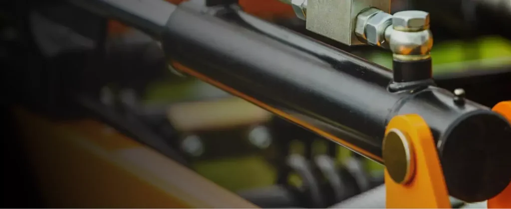
If your task involves pushing a workpiece to a position, clamping it, and then returning—and there is a significant difference in load between the forward and return strokes—you should first evaluate the single-rod design. If the task involves repeatedly moving a worktable left and right, or conducting bidirectional load testing, and you want the speed and force response to be more similar in both directions, you should focus on evaluating the equal-bore double-rod design. This selection is based on differences in the pressure-bearing areas on both sides; it does not mean that a specific type of application can only use a particular layout.
Both single-rod and double-rod configurations can be used for precise positioning; the double-rod configuration is not inherently more accurate. To stop accurately at the midpoint of the stroke, a position sensor is typically required to measure the piston’s position, after which the controller adjusts the control valve based on the target position. This process of continuous measurement, comparison, and correction is known as closed-loop control. The fact that manufacturers offer both single-rod and double-rod servo hydraulic cylinders indicates that positioning capability must be evaluated in conjunction with the entire control system.
Before selecting a model, you should first clarify three questions: at which positions does the cylinder need to stop, what is the allowable deviation, and whether the same performance must be maintained even when the load changes. Also, distinguish between “positioning accuracy” and “repeatability”: the former refers to how close the stop is to the target, while the latter refers to whether the cylinder can stop at similar positions during repeated operations. Applying these requirements separately to both directions of motion is more helpful for suppliers in selecting the appropriate hydraulic cylinders, sensors, and control valves than simply specifying “double-rod, high-precision.”
When Should You Use a Tandem Cylinder?
When you need greater thrust or clamping force, but equipment constraints limit the cylinder bore and the system is not suitable for increasing pressure, you can consider using hydraulic cylinders in series. By arranging multiple pistons along the same axis and mechanically connecting them together, they generate a combined force, thereby increasing the output force within a limited installation width. This approach requires sufficient axial installation length and the ability to provide appropriate oil supply and return passages for each working chamber.
1. Increasing Force Without a Larger Bore
While a standard hydraulic cylinder relies primarily on a single piston to generate thrust or pulling force, a series hydraulic cylinder allows two or more pistons to move together via a common piston rod. When the corresponding working chambers are pressurized simultaneously and each piston exerts force in the same direction, the forces can be superimposed. This configuration increases the total effective area contributing to the output force—that is, the area over which the hydraulic pressure actually pushes the pistons—rather than automatically increasing the system pressure.
You can understand this with a simplified example: Suppose two pistons have effective areas of 30 cm² and 20 cm² in the extension direction, respectively, and the pressure in both inlet chambers is 10 MPa. Ignoring return line back pressure and friction, the theoretical resultant force is 50 kN. Of this, the first piston contributes 30 kN, and the second contributes 20 kN. Therefore, having two pistons does not necessarily mean the output force will exactly double; it must be calculated based on the actual effective areas and the pressures in each chamber.
If the output force of a single cylinder is insufficient, and increasing the bore diameter would cause interference with the frame, a series configuration is worth evaluating. However, if a standard hydraulic cylinder with a larger bore diameter can be installed without issues and meets the requirements, you should first compare the overall dimensions, cost, and maintenance complexity of the two options.
2. Space, Porting, and Synchronization Constraints
Tandem configurations typically use a longer cylinder body to achieve greater output force within a limited width; therefore, they are suitable for layouts where “lateral space is tight but axial space is relatively ample.” If there is insufficient length behind the equipment, a tandem configuration may not fit. When selecting a cylinder, you should include the total cylinder length, full-stroke travel range, hydraulic fitting locations, and space required for maintenance and disassembly in the installation drawing for verification—rather than simply comparing bore sizes.
The port layout must be confirmed in conjunction with the internal fluid circuit: the supplier should provide connection diagrams specifying which working chambers share an inlet, which chambers require a return line, and whether there are any independent drain requirements. Do not simply connect the outlet port of the front cylinder directly to the inlet port of the rear cylinder just because they resemble two hydraulic cylinders. To enable multiple pistons to deliver force simultaneously, you must ensure that the corresponding working chambers receive the required pressure and that the return chambers can drain properly; a mechanical series arrangement does not imply that the fluid circuit should also be a simple series connection.
Flow rate is another common limitation. When multiple working chambers are filled simultaneously, maintaining the same movement speed typically requires a higher total flow rate. Using the area example from earlier, if two pistons move together at 100 mm/s, the theoretical total inflow rate is 30 L/min; if only 15 L/min can actually be supplied, the theoretical speed under the same connection configuration would be approximately 50 mm/s. This illustrates that force amplification does not mean the original pump can maintain its original operating cycle.
In terms of synchronization, the pistons in a common-rod series cylinder are constrained by mechanical connections and will normally move together; there is no need to treat them as two independent actuators for positional synchronization. However, mechanical synchronization does not mean that the pressures in each chamber are automatically equal. If you use two independent series cylinders to drive opposite ends of a pressure plate, additional guidance and synchronization controls must still be designed to ensure the pressure plate remains parallel.
3. Pressing and High-Force Clamping Applications
For press-fitting, pressing, and high-force clamping applications, the value of a series configuration lies in the fact that it allows you to achieve the required axial force even when installation width and available pressure are limited. For example, suppose your press-fit equipment can only accommodate narrow hydraulic cylinders but still has installation space at the rear; in that case, you can evaluate whether a series configuration can meet the press-fit force requirements. This is an application assessment based on structural characteristics; it does not mean that all press-fit equipment should use series cylinders.
You also need to distinguish whether “the high force is applied throughout the entire stroke or only over a short distance after contact with the workpiece.” If the equipment needs to first approach the workpiece rapidly and then apply high force slowly, you should specify the approach speed, pressing speed, and required force separately during selection. The series configuration itself does not automatically switch between rapid approach and pressure application; whether the working chambers can be used in stages depends on the specific structure and valve control circuit design.
For clamping applications, it is recommended that you clearly define the required clamping force, holding time, permissible force variations, and the resistance that must be overcome during retraction. Do not calculate only the force in the clamping direction while ignoring the tensile force required during demolding, extraction, or release of the workpiece. Additionally, a series configuration does not automatically lock or guarantee sustained force retention after a power failure; if the process requires prolonged clamping, a separate pressure-holding circuit must be evaluated, and mechanical locking should be used if necessary. If precise control of the press-fit force is also required, control should be implemented using pressure or force feedback; the actual force applied to the workpiece cannot be determined solely by the number of hydraulic cylinders.
When Is a Double-Acting Telescopic Cylinder Appropriate?
When your equipment requires a long stroke but can only accommodate a short hydraulic cylinder in the retracted position, and the return stroke cannot be reliably accomplished by gravity or other external forces, a double-acting telescoping hydraulic cylinder is worth considering. It reduces the retracted length through multiple nested sleeves and uses hydraulic fluid to drive both extension and retraction. Material-handling trailers, waste compaction, and ejection mechanisms are practical applications for this type of hydraulic cylinder.
Long Stroke in a Short Retracted Length
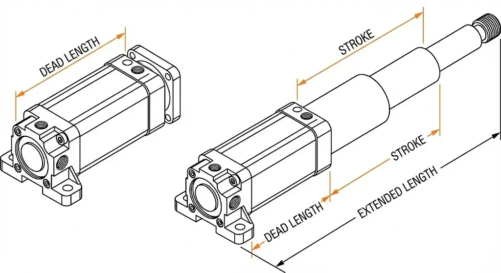
Conventional single-stage hydraulic cylinders must accommodate the entire working stroke within the cylinder barrel; a long stroke typically means a longer cylinder body. Telescopic cylinders, however, distribute the stroke across multiple stages that can be nested inside one another; these stages overlap when retracted and extend sequentially when extended. Therefore, if a conventional long-stroke hydraulic cylinder cannot fit into the equipment in its retracted state, a multi-stage telescopic design may resolve this space constraint.
For example, if your horizontal material-feeding mechanism needs to push material a considerable distance but there is no space behind the frame to install a very long conventional hydraulic cylinder, you should consider a telescopic design. However, the requirement for “long extension” alone is not sufficient to determine the appropriate model; you must also confirm the allowable retracted length and the space available when fully extended. For models mounted on pins at both ends, it is recommended to compare dimensions based on the center-to-center distance of the mounting pins to avoid confusing cylinder length with installation length.
A long stroke also means that support and load-bearing stability when fully extended require greater attention. You should ensure that the push plate or slide table is guided by its own rails to avoid subjecting the extended sleeve to significant lateral thrust. For longer horizontal installation configurations, you should also have the supplier verify whether additional support is required. If the equipment cannot ensure proper alignment or guidance, it should not be selected solely based on space savings, even if the retracted dimensions are suitable.
Retraction Control and Stage Sequencing
Double-acting designs are suitable for applications requiring active retraction of the load. For example, after a horizontal push plate has pushed material out, gravity typically does not assist in its return, and retraction must overcome guide rail friction; in such cases, hydraulic-driven retraction offers practical value. If the load can reliably return under gravity throughout the entire retraction stroke and control requirements permit, single-acting telescopic designs should also be considered.
Conventional sequential telescoping designs typically extend the larger-diameter stage first and retract the smaller-diameter stage first, though the specific sequence depends on the internal structure. When switching between stages, the effective compression area—that is, the area actually pushed by the hydraulic pressure—may change; consequently, force and speed may also vary under the same supply pressure and flow rate. Double-acting means that both directions can be hydraulically driven; it does not mean that each stage can be controlled independently or that a constant speed is naturally maintained throughout the entire stroke.
If your application requires frequent direction changes at mid-stroke, be sure to specify this in advance. Certain models have specific requirements for re-extension after full retraction. Do not interpret “capable of active retraction” as “capable of repeatedly reversing direction at any position”; you should confirm whether the specific model supports your motion cycle.
Complexity, Cost, and Maintenance Trade-Offs
Compared to standard single-stage hydraulic cylinders, multi-stage double-acting designs require more seals, guide components, and internal passages to deliver hydraulic fluid to the retract chambers of each stage. This typically results in more complex machining, assembly, and troubleshooting, as well as higher procurement and maintenance costs. The exact cost difference depends on the number of stages, size, pressure, and customization requirements, so it cannot be generalized using a fixed ratio.
Therefore, you should first determine whether the space savings are sufficient to offset these additional requirements. If a standard single-stage double-acting hydraulic cylinder can already fit into the space and perform the required motion, it is usually more straightforward to prioritize a solution with a simpler design. However, if a telescoping cylinder allows the equipment to be retracted for storage or transport, or enables long-distance pushing and pulling that would otherwise be impossible, there is a stronger case for accepting the added complexity. This selection decision is based on structural and maintenance requirements, rather than which type of hydraulic cylinder is always more cost-effective.
Tie-Rod vs. Welded vs. Mill-Type Construction
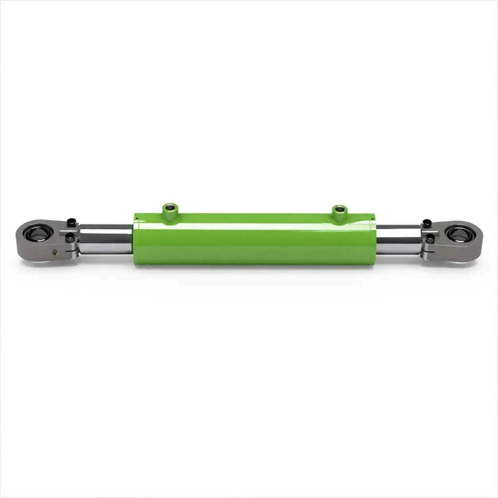
The tie-rod type clamps the cylinder barrel and end caps using long external tie rods; the welded type connects major components such as the cylinder barrel and cylinder bottom via welding; and the Mill-Type emphasizes a robust design for heavy-duty industrial applications, which can utilize either bolted or welded constructions. Therefore, these three designations are not entirely mutually exclusive classifications. What you really need to compare are ease of maintenance, specific load-bearing capacity, installation dimensions, and environmental adaptability—rather than judging which type is “more advanced” based solely on its name.
Serviceability and Standardization
Tie-rod-type cylinders typically allow for easy removal of end caps, inspection of the cylinder barrel, and replacement of internal components. Furthermore, many industrial series feature standardized mounting dimensions, which facilitate equipment design and spare parts replacement. However, standardized mounting dimensions do not mean that internal components from different brands are interchangeable. For example, while a series may specify compliance with ISO mounting dimensions—which primarily helps you verify mounting interfaces—this does not guarantee that seal kits, pistons, or guide assemblies are interchangeable.
Welded-type cylinders are not necessarily non-serviceable. The front guide seal assemblies on many models can be removed, allowing the piston rod assembly to be extracted and seals to be replaced; however, the cylinder barrel and cylinder base, which are welded together, are generally not as easy to replace individually as in rod-type designs. Mill-type cylinders with removable end caps can also provide good serviceability. Prince’s welded cylinder products come with parts manuals, and some models explicitly feature threaded guide seal assemblies.
Pressure, Shock, and Duty-Cycle Capability
The three designs cannot be simply categorized as “rod-type for low pressure, welded-type for medium pressure, and Mill-Type for high pressure.” Pressure ranges across different series may overlap. For example, Prince offers both rod-type and welded-type products rated at 3,000 psi, indicating that the design designation alone does not determine the pressure rating; however, the same nominal pressure does not imply that the two designs have the same shock resistance or service life.
You also need to distinguish between normal operating pressure, instantaneous pressure peaks, and duty cycles. Duty cycles include actuation frequency, loading time, pressure hold time, and rest time; repeated loading can cause fatigue—that is, gradual damage to parts resulting from repeated stress cycles. Mill-Type products are generally suitable for heavy-duty and harsh industrial applications, but “heavy-duty” does not imply unlimited shock resistance; you must still verify the operating conditions for the specific model.
A practical approach is to provide the supplier with information on the number of cycles per minute, daily operating time, load variations, and emergency stop situations. For example, an adjustment mechanism that operates only occasionally cannot be selected under the same operating conditions as a press-fitting mechanism that performs continuous reciprocating motion, even if their maximum pressures are the same. Furthermore, the pressure withstand test pressure should not be equated with the long-term operating pressure, and the internal cushioning of the cylinder should not be assumed to absorb all the kinetic energy of the load; when heavy loads stop at high speeds, the cushioning capacity must be calculated, and external deceleration control should be employed when necessary.
Size, Mounting, and Environmental Protection
Weld-on types lack external tie rods and are often easier to design as compact, circular housings, making them well-suited for the space around a frame or linkage. Tie-rod types have end caps and tie rods that occupy some space, though compact series are available; Mill-Type cylinders may increase in size and weight due to their more robust end caps, connection points, and support designs. You should compare the overall dimensions under the same thrust, stroke, and mounting requirements—do not compare only the cylinder bore diameter.
The mounting method also affects the available load-carrying capacity. For fixed-mount applications, ensure the hydraulic cylinder is aligned with the load’s direction of motion; if the cylinder needs to swing during operation, select a connection type that allows for the corresponding rotation. Even if the cylinder body itself can withstand pressure, the mounting brackets, pins, or rod-end connections may reach their load limits first. Manufacturer catalogs may specify pressure limits based on different mounting configurations, so do not overlook the parameters corresponding to the specific mounting method.
Environmental protection must be selected separately. Welded designs are not automatically corrosion-resistant simply because the housing is welded, nor are Mill-Type designs automatically suitable for high temperatures merely because of their heavy-duty construction. In damp outdoor environments, check the piston rod’s surface treatment and external coatings; in dusty environments, pay attention to dust seals and necessary rod protection; when using special hydraulic fluids, confirm the compatibility of sealing materials.
Typical Industrial and Mobile Applications
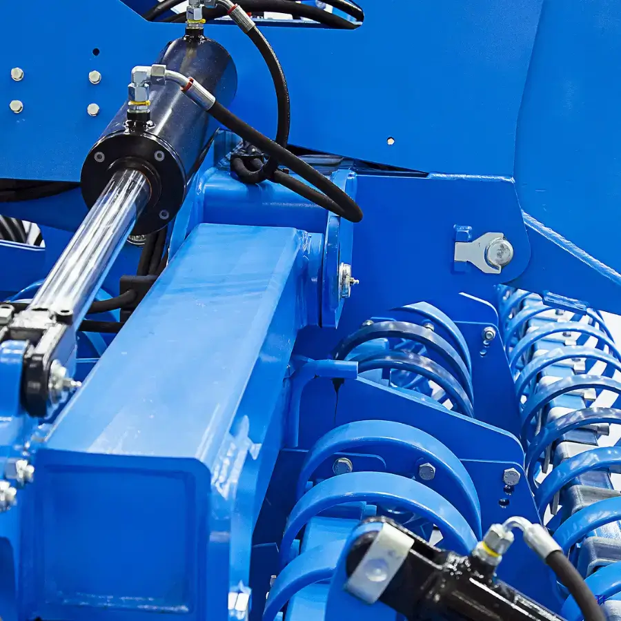
For machine tool fixtures, assembly lines, and general factory equipment, if you prioritize standard interfaces, spare parts management, and ease of disassembly and maintenance, you should prioritize evaluating tie-rod cylinders. For push-pull, lifting, or rotating mechanisms on mobile machinery, if chassis space is limited and mounting brackets and hydraulic ports need to be coordinated with the overall machine layout, you should focus on comparing welded-type cylinders. For long-term, heavy-duty applications such as metallurgical equipment and heavy-duty pressing mechanisms, it is worth including Mill-Type cylinders in your list of candidates. These are common guidelines for selection and do not represent strict industry boundaries.
For example, if an indoor clamping station already has a suitable standard rod-type cylinder interface, there is no need to change the structure simply because “the welded type looks sturdier”; rod-type cylinders can also be used on mobile equipment if space and load conditions permit. For heavy-duty production equipment, you should not place an order based solely on the “Mill-Type” designation; instead, you should ask the supplier to confirm suitability based on load cycles, installation methods, and environmental conditions.
How Do You Select the Right Double Acting Cylinder Type?
When selecting a double-acting hydraulic cylinder, you should first determine how the load will move and how much force is required, then assess the installation space, operating environment, and control requirements. For general push-pull motions, start by evaluating single-rod cylinders; for bidirectional symmetrical output, consider double-rod cylinders with equal rod diameters; when cylinder bore diameter is limited but greater force is needed, evaluate series-connected cylinders; and when the retracted length is short but the stroke is long, consider telescopic cylinders. Next, based on load-bearing, maintenance, and installation requirements, choose between a tie-rod, welded, or mill-type design.
1. Define Push and Pull Force at Working Pressure
First, you need to determine the maximum load during both extension and retraction, including the force generated by the workpiece’s weight, motion friction, the force required for acceleration, and process resistance from operations such as press fitting or clamping. If the hydraulic cylinder is driven by a link mechanism, the required push and pull forces will vary with angle; therefore, the workpiece’s weight cannot be directly considered as the hydraulic cylinder’s load.
The output force should be calculated based on the actual pressure achievable in the hydraulic cylinder’s working chamber, rather than directly using the pump’s maximum pressure or the cylinder’s rated pressure. For a standard single-rod design, the extension side utilizes the full piston area, while the retraction side deducts the piston rod area; the actual net force must also account for the reverse reaction force caused by return line back pressure and friction. Therefore, the ability to push does not necessarily mean the ability to pull; both directions must be calculated separately.
For example, suppose you need 40 kN of extension thrust, with an available pressure of 10 MPa inside the cylinder. Ignoring back pressure and friction, the theoretically required area is 4,000 mm², corresponding to a cylinder bore of approximately 71.4 mm. This is only a preliminary lower limit and cannot be used directly as the final ordering specification; you must also consider actual losses, load fluctuations, and appropriate design margins when selecting and verifying the specific model.
2. Set Stroke, Speed, and Duty Cycle
Stroke refers to the distance the piston travels; you should determine this based on the two limit positions of the mechanism, while also checking the installation dimensions of the hydraulic cylinder in both the retracted and extended positions. If a long stroke is required but a standard single-stage hydraulic cylinder does not fit in the available space when retracted, you may consider a telescopic cylinder; however, you must also confirm that the output force at each stage and the speed changes during switching meet the operational requirements.
Speed must be determined in conjunction with the supply flow rate. Theoretically, the required flow rate equals the effective area on the inlet side multiplied by the speed of movement; therefore, as the cylinder bore increases, a higher flow rate is typically required to maintain the same speed. Since the effective areas for extension and retraction differ in single-rod cylinders, the inlet and return flow rates should be calculated separately for each direction to avoid a situation where the pump flow is sufficient but the valves or return lines become the limiting factors.
We recommend specifying the motion cycle as “extend distance and time—load or hold pressure time—retract time—dwell time,” and supplementing this with the number of cycles per hour and daily operating hours. This will help suppliers assess requirements for flow rate, seal wear, and heat generation. If the equipment requires frequent directional changes or high-speed operation, simply stating “500 mm stroke” is far from sufficient.
3. Check for Buckling, Side Load, and Mounting Geometry
Buckling is a instability phenomenon in which a slender piston rod suddenly bends sideways under axial pressure. Long strokes, relatively thin rods, and unfavorable support configurations all increase the risk; therefore, passing a thrust calculation does not guarantee that the piston rod is sufficiently stable. You must perform calculations based on the actual installation configuration and the most unfavorable extended position, rather than relying solely on the rod diameter.
A lateral load is a force applied from the side that causes the piston rod to deviate from its axis of motion. For example, when a hydraulic cylinder drives a horizontal slide, the weight of the slide and any eccentric forces should be borne by the guide rails as much as possible, while the hydraulic cylinder is responsible for axial thrust and pull. If you increase the piston rod diameter to improve stability, you must also recheck the retracting force, as a larger diameter reduces the pressure-bearing area on the rod side of a single-rod design.
When selecting a cylinder, it is recommended to submit an installation drawing showing both stroke end positions, indicating pin locations, rod-end connections, and load guidance methods. If the hydraulic cylinder needs to swing with the mechanism, the connection must allow for corresponding rotation; if the lever arm becomes very short when the mechanism approaches certain angles, check whether exceptionally high thrust is required at that position. Do not use higher pressure to compensate for misalignment or mechanism binding.
4. Match Seals and Materials to Fluid and Temperature
To determine whether a seal is suitable, you must consider the hydraulic fluid, temperature, pressure, and operating speed simultaneously. The hydraulic fluid is the liquid used in the system to transmit force, such as mineral hydraulic oil, water-glycol hydraulic fluid, or other specialty fluids. Just because a seal is suitable for standard mineral oil does not mean it is suitable for all flame-retardant or biodegradable hydraulic fluids; manufacturers must match the seals and surface materials to the specific fluid.
You should provide the exact name or product specifications of the hydraulic fluid, as well as the minimum startup temperature, normal oil temperature, and the highest temperature that may occur—not just the temperature of the workshop where the equipment is located. Cold-start conditions outdoors and the hot oil state after operation may impose different requirements on seal elasticity and fluid flowability. For slow, smooth motion, you should also consider whether seal friction could cause “creep”—that is, a phenomenon where the motion pauses briefly and then jerks forward.
5. Confirm Cushioning, Position Sensing, and Load Holding
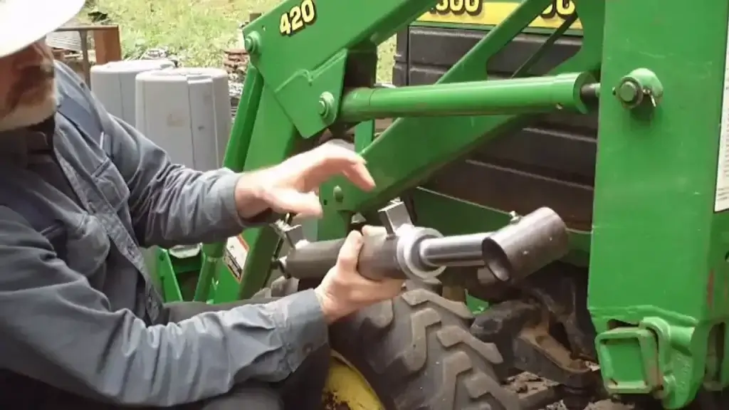
Cushioning is a function that decelerates the motion as it approaches the end of the stroke to reduce impact. If the motion load is heavy or the speed is high, you need to provide the moving mass, the speed at the end of the stroke, and the available deceleration distance so that the supplier can calculate the cushioning capacity. Built-in cushioning has a limited scope of application and cannot be assumed to replace the entire equipment’s speed control or absorb all stopping energy.
Position detection should be selected based on the task. If you only need to confirm arrival at either end, limit switches may be sufficient; if precise stopping is required midway through the stroke, you should evaluate position sensors and closed-loop control—that is, continuously measuring the current position and adjusting the valve to bring it close to the target. You should specify the allowable position error and repeatability requirements, rather than simply requesting a “high-precision hydraulic cylinder.”
A double-acting design does not automatically lock the load in place. If position holding, power-off holding, or controlled lowering of heavy loads is required, a separate load-holding circuit should be designed. Hydraulically controlled check valves are primarily used to prevent reverse flow and maintain position; for lowering operations where gravity causes the load to accelerate on its own, solutions such as balancing valves—which regulate oil discharge and control load movement—typically need to be evaluated. Whether mechanical locking or support is also required should be determined based on the consequences of failure; one should not rely solely on a standard directional control valve to shut off the oil circuit.
6. Review Standards, Testing, and Documentation
When reviewing standards, you need to distinguish between mounting dimensions, system requirements, and the purpose of acceptance testing. For example, ISO 6020-2 covers the mounting dimensions of a specific series of single-rod hydraulic cylinders; ISO 4413 covers general rules and safety requirements for hydraulic systems and their components; and ISO 10100 specifies acceptance and functional testing for hydraulic cylinders. These standards address different issues; the phrase “complies with ISO standards” cannot be used as a substitute for the specific scope of application and acceptance requirements.
Before placing an order, it is recommended that you confirm with the supplier which standards and versions are being used, and agree on test items, conditions, and criteria for acceptance, including applicable pressure resistance, leakage, full-stroke operation, and checks of cushioning or sensor functions. Do not interpret passing a pressure resistance test as verification of long-term cycle life; if the equipment has explicit durability requirements, the corresponding verification methods should be agreed upon separately.
Technical documentation should, at a minimum, include approved installation drawings, rated operating parameters, port and circuit connection requirements, information on seal compatibility with hydraulic fluid, a spare parts list, and maintenance instructions. When test reports are required, you should also confirm that the reports correspond to the delivered model or serial number.
Double Acting Cylinder Type Selection Matrix
You can first narrow down the list of candidates based on your primary requirements, and then check the operating pressures, mounting dimensions, and control conditions. The “Preferred Options” in the table below are preliminary recommendations and do not necessarily represent the most suitable choice for all operating conditions. Additionally, piston configurations and cylinder body structures can be combined; for example, you can choose a double-rod hydraulic cylinder with a tie-rod structure.
| Primary Requirements | Types to Evaluate First | Reasons for Selection | Conditions That Must Be Verified | Situations Where Direct Selection Is Not Recommended |
|---|---|---|---|---|
| More symmetrical output force and speed in both directions | Equal-diameter double-rod hydraulic cylinder | Identical effective pressure areas on both sides, facilitating symmetrical output | Consistent rod diameter at both ends, matching fluid supply and load conditions | No clearance for piston rod movement at the rear end |
| Short retracted length, long working stroke | Double-acting telescoping hydraulic cylinder | Multiple telescoping sleeves overlap when retracted, providing a long stroke when extended | Thrust and pull forces at each stage, operating sequence, guidance, and return flow capacity | Requires constant speed over the full stroke or frequent mid-stroke direction changes without specialized design |
| Limited cylinder bore but requiring high output force | Tandem hydraulic cylinder | Multiple mechanically linked pistons provide combined force | Sufficient axial length, with oil flow rate and connection load-bearing capacity meeting requirements | Equipment length is also limited, or existing pumps cannot meet the required operating speed |
| Emphasis on standardization and ease of industrial maintenance | Standard series tie-rod hydraulic cylinders | Wide range of mounting configurations, typically facilitating disassembly and maintenance | Mounting interfaces, maintenance kits, spare parts availability, and disassembly space | Assuming direct replacement based solely on identical bore diameter and stroke |
| Limited installation space in mobile equipment | Compact welded hydraulic cylinders | No external long tie rods, facilitating the arrangement of mounting brackets and oil ports in conjunction with the entire machine | Full-stroke dimensions, mounting loads, fitting locations, and environmental protection | The real constraint is the retracted length required for long strokes; standard welded cylinders still cannot fit |
Best Choice for Equal Force and Speed
If your worktable requires repeated left-to-right movement and you want the performance in both directions to be as close as possible, you should prioritize evaluating the equal-rod-diameter double-rod design. Since the pressure-receiving areas on both sides are identical, the theoretical output force is the same under the same effective pressure differential; the theoretical speed is the same under the same input flow rate. You still need to confirm the rod diameters at both ends and the control conditions; “double-rod” should not be equated directly with automatic constant speed or high precision. If space is limited at the rear end, a single-rod design paired with separately matched bidirectional flow control is also worth considering.
Best Choice for Compact Long Stroke
If a standard single-stage hydraulic cylinder does not fit inside the equipment when retracted, but you require a long stroke and active retraction, consider a double-acting telescopic cylinder. For example, a horizontal material-pushing mechanism that requires both a long push distance and hydraulic-driven return would fit this evaluation criteria. Before purchasing, verify the retracted installation length, total stroke, and the thrust and pull forces for each stage; do not assume that the output force of the highest stage represents the capacity for the entire stroke. If frequent mid-stroke directional changes are required, have the supplier explicitly confirm that the model supports this type of operating cycle.
Best Choice for High Force in Limited Bore Space
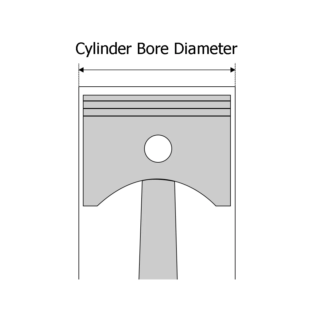
If the cylinder bore diameter is already limited by the frame width but there is still sufficient length at the rear, consider evaluating series-connected hydraulic cylinders. These cylinders generate force through multiple pistons connected by a common rod, increasing the total effective pressure area without automatically raising system pressure. You should request that the supplier provide actual thrust and pull force calculations and hydraulic connection diagrams, and verify the total flow rate based on the target speed. If a standard large-bore hydraulic cylinder can be installed and meets the requirements, you should also compare costs and maintenance complexity; the increased length and complexity of a series-connected configuration must yield tangible benefits.
Best Choice for Standard Industrial Serviceability
If your factory equipment prioritizes standard mounting interfaces, spare parts management, and disassembly for maintenance, you should prioritize evaluating mature rod-type product lines. However, standardization primarily applies to specific mounting dimensions and configurations; it does not imply that internal components across different brands are interchangeable. Before replacing an old cylinder, at a minimum, verify the mounting hole spacing, retracted length, rod-end threads, and port locations, and confirm the seal repair kit model. If your existing welded cylinders are already serviceable and spare parts are readily available, there is no need to change the design solely for the sake of “serviceability.”
Best Choice for Mobile Equipment Packaging
If the frame, linkages, and piping of mobile machinery create tight installation spaces, prioritize compact welded cylinders and coordinate the placement of mounting brackets and hydraulic ports with the overall machine layout. Here, it is important to distinguish between “excessive width” and “excessive length when retracted”: the former can often be resolved with a compact welded design, while the latter—if caused by a long stroke—may require a telescopic design. We recommend using the installation drawing to verify the two stroke end points and the mid-stroke position, while allowing for space for fittings, hose bends, and maintenance. Finally, confirm that the dust protection, coating, and piston rod surface treatment are suitable for the operating environment.
What Should B2B Buyers Confirm With a Manufacturer?
When purchasing double-acting hydraulic cylinders, you need to confirm performance specifications, manufacturing requirements, and after-sales support, and include key details in drawings and technical documents agreed upon by both parties to avoid discrepancies in configurations between quotes, samples, and mass-produced products.
Rated and Proof Pressure
Confirm the rated working pressure, permissible instantaneous peak pressure, as well as the pressure, duration, and pass criteria for the pressure test. The pressure test pressure must not be used as the long-term working pressure, and passing the test does not equate to verification of cycle life. If the equipment is subject to emergency stops or shock loads, inform the manufacturer in advance.
Material, Welding, and Surface-Finish Specifications
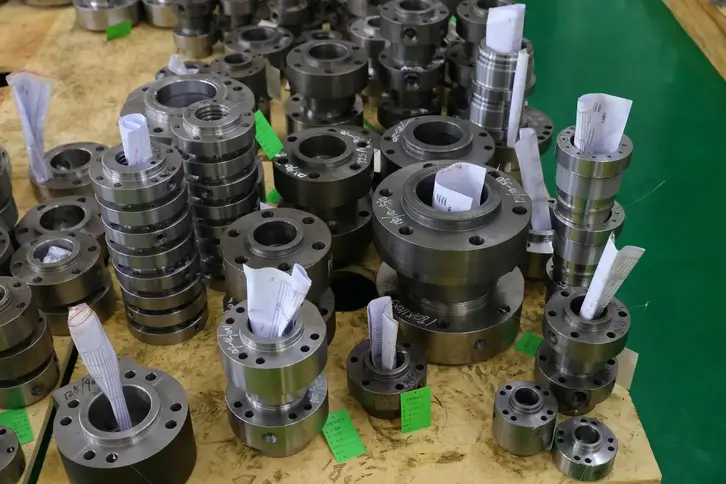
Require the manufacturer to specify the materials for the cylinder barrel, piston rod, and mounting components, as well as any necessary heat treatment, weld inspection, and surface treatment requirements. Do not accept vague descriptions such as “high-strength steel” or “rust-proof treatment”; you should provide details on temperature, humidity, dust, or corrosion conditions so that the manufacturer can confirm the appropriate configuration.
Seal Brand, Spare Parts, and Repairability
In addition to the seal brand, confirm that the specific materials and models are suitable for your hydraulic fluid, temperature, and operating speed. Before purchasing, clarify the maintenance kit number, spare part lead times, and whether replacing seals requires removing the entire hydraulic cylinder or using specialized tools. Also, agree on advance notice for any configuration changes.
Inspection Records and Dimensional Consistency
Pay close attention to stroke, retracted installation length, mounting hole spacing, rod-end threads, and port orientation. Confirm which items are inspected on a per-unit basis and which are subject to sampling. Identical bore diameter and stroke do not guarantee direct interchangeability. Critical dimensions and test records must correspond to the delivered product and the confirmed drawing version—not merely a sample report.
Customization, Lead Time, and Batch Traceability
Confirm the scope of customization, delivery dates for samples and production runs, and the conditions under which the lead time begins to be calculated. Additionally, require that serial numbers or lot numbers be linked to manufacturing configurations and inspection records. For example, if a batch of products develops leaks, you should be able to use this information to determine the extent of the issue and accurately order the corresponding replacement parts.
Frequently Asked Questions About Double Acting Cylinder Types
Is a Differential Cylinder Always Double-Acting?
In standard hydraulic terminology, yes. A differential hydraulic cylinder refers to a single-rod, double-acting hydraulic cylinder in which the effective pressure areas on both sides are different. The term “differential” here describes the difference in area; it does not mean you must use a differential circuit—that is, a configuration where the return flow from the rod side is directed back to the non-rod side.
Do Double-Rod Cylinders Produce Equal Force in Both Directions?
When the rod diameters on both sides are the same and the effective pressure difference in both directions is equal, the theoretical output force is the same. Actual output is also affected by friction and return line back pressure. Therefore, you need to confirm the rod diameters at both ends and the operating conditions; you cannot simply assume that the force in both directions is exactly the same just because it is labeled “double-rod.”
Can Telescopic Cylinders Be Double-Acting?
Yes. Double-acting telescopic hydraulic cylinders are driven by hydraulic fluid to extend and retract, making them suitable for mechanisms that require a long stroke, have limited retraction space, and cannot rely on gravity for reliable return. However, the thrust and pull forces at each stage, as well as the sequence of operations, must be verified separately.
What Is the Difference Between Tandem and Duplex Cylinders?
According to Parker’s classification, in a tandem cylinder, the pistons are connected by a common piston rod and move together to combine their output forces; in a duplex cylinder, the pistons are not directly connected and are typically used to achieve multiple stopping positions. Naming conventions may vary among manufacturers, so it is best to consult the structural drawings to confirm whether the pistons are connected and how the strokes are combined.
Work with a IATF 16949 Certified Blind Rivet Manufacturer
Get High Quality Rivets Instead of Huck and Avdel Rivets
Explore Rivmate Cases

Hey There, I'm Melody!
We are a hydraulic cylinder manufacturer. For over 20 years, we have focused on producing reliable hydraulic cylinders. Need a hydraulic cylinder solution? Feel free to contact us.