
Home / How Does a Double Acting Hydraulic Cylinder Work?
How Does a Double Acting Hydraulic Cylinder Work?
- Author: GY Hydraulic
- 20+ Years of Manufacturing
A double-acting hydraulic cylinder allows the piston rod to move actively in both directions by alternately supplying and returning oil through two ports. When pressurized oil enters the rodless chamber—that is, the side without the piston rod—the hydraulic pressure pushes the piston, causing the piston rod to extend; when pressurized oil enters the rod chamber, the piston rod retracts. The directional control valve is responsible for changing the flow direction of the hydraulic oil, allowing you to control the extension, retraction, and stopping of the hydraulic cylinder.
Double-acting hydraulic cylinders are suitable for equipment requiring bidirectional power, stable return travel, or frequent reciprocating motion, such as construction machinery, lifting equipment, and automated production lines. If the equipment only requires unidirectional output and can rely on springs, gravity, or external loads for return travel, a single-acting hydraulic cylinder is typically simpler.
A common misconception is that the force and speed of a hydraulic cylinder are exactly the same during extension and retraction. When determining whether a hydraulic cylinder is suitable, do not simply check the extension thrust; also confirm that the retraction pull force, return speed, and mounting orientation can meet the actual load requirements. Below, we will further explore each operating process by tracing the direction of fluid flow through the two ports.
Table of Contents
How Does a Double Acting Hydraulic Cylinder Work?
A double-acting hydraulic cylinder relies on pressurized oil alternately entering both sides of the piston to actively extend and retract the piston rod. It typically has two working ports: one connected to the rodless chamber and the other to the rod chamber. A directional control valve changes the oil flow paths for inlet and return, thereby controlling the direction of the hydraulic cylinder’s movement.
This design is suitable for equipment requiring bidirectional power, stable return travel, speed control, or frequent reciprocating motion. If the equipment only needs to perform work in one direction and can rely on gravity, springs, or an external load for return travel, a single-acting hydraulic cylinder may be simpler and require fewer lines and control components.
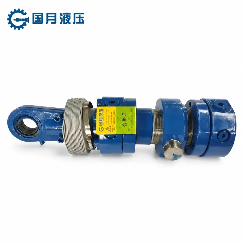
① Oil Enters the Cap End to Extend the Rod
The rodless chamber is the side of the piston not connected to the piston rod, typically located near the bottom end cap of the hydraulic cylinder. When pressurized oil enters the rodless chamber, the oil pressure acts on the entire effective area of the piston, pushing the piston toward the rod end and causing the piston rod to extend.
The theoretical extension force of the piston rod can be estimated using the following formula:
Extension Force = System Pressure × Piston Area
For example, when the pressure remains constant, a larger cylinder bore results in a larger piston area and, consequently, a greater theoretical extension force. However, the actual output force is also affected by seal friction, internal leakage, pressure losses in the piping, and the direction of the load; therefore, the theoretical value should not be directly taken as the actual thrust that the equipment can reliably deliver during stable operation.
When selecting a cylinder, you should first determine the maximum load the equipment needs to overcome, and then verify whether the cylinder bore and actual operating pressure can provide sufficient extension force. A common mistake is to calculate based solely on the hydraulic system’s maximum rated pressure without confirming the operating pressure that the equipment can reliably maintain during long-term operation.
② Oil Enters the Rod End to Retract the Rod
When the directional control valve switches the oil circuit, pressurized oil enters the rod side—that is, the side where the piston rod is located. The oil pressure pushes the piston toward the non-rod end, causing the piston rod to retract.
Since the piston rod occupies a portion of the area, the effective pressure-receiving area of the rod side is smaller than that of the non-rod side. Therefore, at the same pressure, the theoretical retraction force of a standard single-rod, double-acting hydraulic cylinder is typically less than the extension force:
Retraction Force = System Pressure × (Piston Area − Piston Rod Cross-sectional Area)
With the same input flow rate, the piston rod typically retracts faster than it extends because the effective area on the retraction side is smaller. You cannot assume that the force and speed are the same in both directions. When selecting a cylinder, you should verify the extension thrust, retraction pull, and speeds in both directions simultaneously—especially when the retraction process also requires lifting, pulling, or clamping a load.
③ The Opposite Chamber Returns Oil to the Tank
When pressurized oil enters one chamber, the piston pushes the hydraulic oil out of the opposite chamber. For example, when pressurized oil enters the rodless chamber to extend the piston rod, the oil in the rod chamber must flow back to the tank through the return line; when the piston rod retracts, the oil in the rodless chamber must be expelled.
If the return line is blocked, valves are not opened correctly, or the line and fittings are undersized, high back pressure may develop on the return side. Back pressure is the pressure that hinders the discharge of hydraulic fluid; it reduces the hydraulic cylinder’s actual output force and may cause slow movement, overheating, or unstable operation.
During commissioning, perform a full extension and retraction cycle separately to observe whether the hydraulic cylinder exhibits a noticeable drop in speed, crawling, abnormal overheating, or increased pressure. If the problem occurs in only one direction of movement, focus on inspecting the return line, hoses, fittings, and control valves corresponding to that direction.
④ A Directional Control Valve Reverses the Flow Path
A directional control valve determines which port the pressurized oil enters, while connecting the other port to the return line. When the spool changes position, the inlet and return routes change accordingly, causing the hydraulic cylinder to switch from extension to retraction, or from retraction to extension.
The directional control valve also affects the state of the hydraulic cylinder when it stops. Depending on the spool’s neutral position, the ports may be sealed, relieved, or connected to the tank; therefore, valves should not be selected based solely on the number of ports. You must also determine whether the load must be held at a specific position and whether there is a risk of free fall or unintended movement when the equipment stops. For vertical loads or equipment requiring reliable position holding, it is generally not sufficient to rely solely on directional control valves; safety control components, such as load-holding valves, must also be configured based on a system risk assessment.
During installation, do not determine port functions based solely on hose positions. First, confirm which port connects to the rodless chamber and which connects to the rod chamber, then set the valve direction according to equipment requirements. If the actual movement direction of the hydraulic cylinder is opposite to the control command, first check the hose connections and valve control logic; do not directly adjust the system pressure.
Which Components Make Bidirectional Motion Possible?
A double-acting hydraulic cylinder is capable of bidirectional movement not merely because it has two ports, but because the cylinder barrel, piston, piston rod, seals, and control valve collectively form a hydraulic circuit that can be pressurized alternately. Incorrect selection of any single component may result in insufficient thrust, unstable speed, internal leakage, or an inability to hold the load.
Barrel, Piston, and Piston Rod
The barrel is the main component that houses the piston’s movement and contains the pressurized hydraulic fluid. The piston is mounted inside the barrel, dividing the space into a non-rod chamber and a rod chamber. When pressurized fluid enters one side, the pressure differential pushes the piston toward the other side, thereby generating linear motion.
The piston rod is connected to the piston and is responsible for transmitting hydraulic force to external equipment. The cylinder bore diameter determines the piston’s pressure-bearing area, while the piston rod diameter affects the effective area during retraction. Therefore, in a typical single-rod, double-acting hydraulic cylinder, the extension force is usually greater than the retraction force at the same pressure.
You can use the following relationships for a preliminary assessment:
Extension force = Pressure × Piston area
Retraction force = Pressure × (Piston area − Piston rod cross-sectional area)
When selecting a hydraulic cylinder, do not focus solely on the bore diameter and stroke. You must also check the piston rod diameter, mounting configuration, load direction, and lateral forces. If the piston rod is subjected to significant off-center loading—that is, when the load direction does not align with the piston rod’s centerline—the piston rod, guide bushings, and seals may wear out more quickly. Hydraulic cylinders are designed to withstand axial thrust and pull loads and should not be used as the primary lateral guide rails for equipment.
Cap-End and Rod-End Ports
The port on the rodless chamber connects to the side of the piston without the piston rod, while the port on the rod chamber connects to the side where the piston rod is located. When pressurized fluid enters the rodless chamber, the piston rod extends; when pressurized fluid enters the rod chamber, the piston rod retracts. At the same time, the hydraulic fluid on the opposite side must be discharged smoothly through the corresponding port.
Both ports must be capable of withstanding the system’s operating pressure and meeting the actual flow rate requirements. If the ports, fittings, or hoses are too small, they will restrict fluid flow, increase pressure loss and heat generation, and may prevent the hydraulic cylinder from achieving the expected speed. The speed of a hydraulic cylinder can be estimated using the following formula:
Speed = Flow Rate into the Chamber ÷ Effective Area of That Chamber
Since the effective area of the rod chamber is smaller, the piston rod typically retracts faster than it extends at the same flow rate. When selecting a cylinder, you should calculate the speed for both directions separately, rather than using a single speed to represent the entire working cycle.
A common mistake is arbitrarily connecting the two ports based on the installation position. This may cause the actual direction of the hydraulic cylinder’s movement to be opposite to the control command. Before connecting, verify the ports for the rodless chamber and rod chamber according to the hydraulic cylinder drawings, and then check the inlet, return, and working ports of the directional control valve.
Bidirectional Piston and Rod Seals
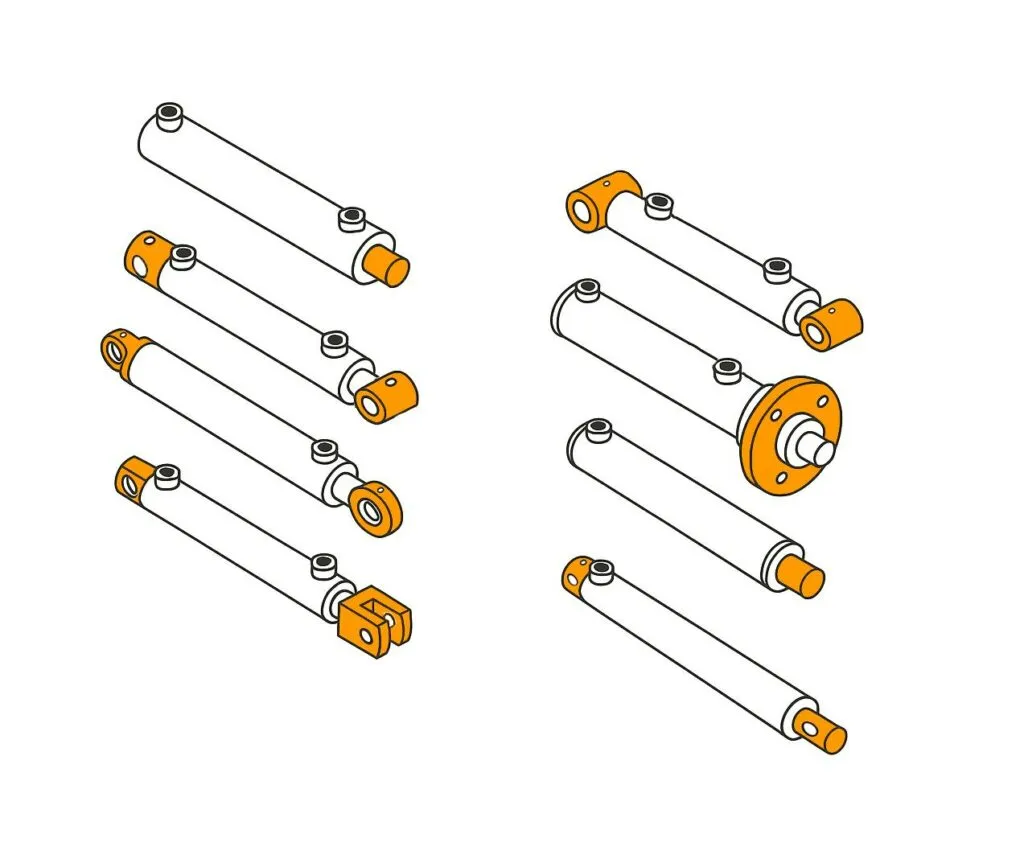
Piston seals are installed between the piston and the inner wall of the cylinder barrel to reduce internal leakage between the two oil chambers. In a double-acting hydraulic cylinder, both sides of the piston are subjected to alternating pressures; therefore, the piston seal must be designed to withstand pressure in both directions. If the seal is designed to withstand pressure in only one direction, leakage or seal failure may occur when pressure is applied in the opposite direction.
Piston rod seals are installed at the front end of the hydraulic cylinder to prevent hydraulic fluid in the rod chamber from leaking outward along the piston rod. They are typically used in conjunction with dust seals and guide elements: dust seals reduce the ingress of dust and moisture into the hydraulic cylinder, while guide elements help limit lateral movement of the piston rod and piston.
You cannot select seals based solely on the dimensions of the hydraulic cylinder. You must also verify the operating pressure, fluid type, temperature, piston speed, surface quality, and operating environment. For example, high-temperature, low-temperature, water-containing media, or outdoor dusty environments may require different seal materials and protective designs.
If the piston rod moves slowly after coming to a stop, it does not necessarily indicate an external oil leak. When internal leakage occurs in the piston seal, hydraulic fluid may flow from the high-pressure chamber into the low-pressure chamber, but no obvious oil traces will be visible externally. When diagnosing the issue, you should simultaneously check for internal valve leakage, load variations, and the condition of the cylinder’s internal seals; do not simply replace the rod seal just because you see the piston rod moving.
Directional, Flow-Control, and Relief Valves
Directional control valves are responsible for changing the flow path of hydraulic fluid. When the valve switches positions, pressurized fluid enters one side of the hydraulic cylinder, while the other side is connected to the return line, thereby allowing the piston rod to alternate between extension and retraction. When selecting a directional control valve, you must verify that the valve’s operating pressure, rated flow rate, control method, and neutral position functionality meet the equipment’s requirements.
Flow control valves regulate the speed of a hydraulic cylinder by limiting fluid flow. In operating conditions where the load may actively pull the cylinder—such as vertical descent or tilting movements—restricting the inlet flow alone may not provide stable speed control; in such cases, a combination of return line throttling or load control solutions is typically required. However, the specific circuit must be designed based on the load direction and safety requirements; valve positions cannot simply be swapped.
A relief valve is used to limit the maximum system pressure. When the pressure reaches the set value, it diverts a portion of the fluid back to the tank, reducing the risk of damage to the pump, piping, and hydraulic cylinder due to overpressure. The relief valve itself is not responsible for changing the direction of the hydraulic cylinder and should not be used as a speed control element over the long term, as this may result in energy loss and increased oil temperature.
When configuring valves, it is recommended that you first record the required load, speed, and stopping conditions for both directions of the hydraulic cylinder. Then, select directional control valves and flow control valves based on the required flow rate, and set pressure protection according to the system’s allowable pressure. Do not arbitrarily increase the relief valve’s set pressure to achieve greater thrust, as the hydraulic cylinder, pump, hoses, fittings, and valves must all be capable of withstanding the adjusted pressure.
Why Are Extension and Retraction Forces Different?
The extension force of a standard single-rod, double-acting hydraulic cylinder is typically greater than its retraction force because the piston rod occupies a portion of the effective area. When the piston rod extends, the hydraulic fluid acts on the entire piston area; when the piston rod retracts, the hydraulic fluid acts only on the annular area remaining after subtracting the cross-sectional area of the piston rod. At the same pressure, the larger the effective area, the greater the theoretical force generated by the hydraulic cylinder.
This difference primarily applies to standard single-rod, double-acting hydraulic cylinders. When the piston rod diameters on both sides of a double-rod hydraulic cylinder are the same, the effective areas in both directions are nearly equal; therefore, the theoretical extension and retraction forces are also closer to each other.
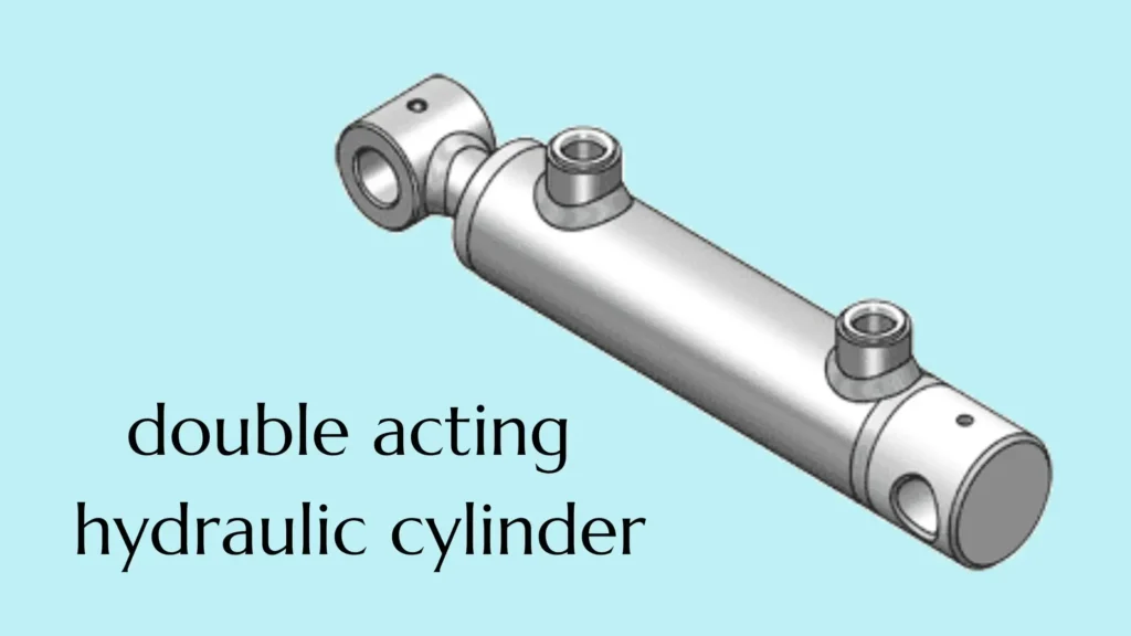
Full Piston Area During Extension
When the piston rod extends, pressurized fluid enters the rodless chamber—that is, the side without the piston rod. Since there is no piston rod occupying space on this side, the hydraulic pressure can act on the entire piston end face.
The formula for calculating the piston area is:
Piston Area = π × Cylinder Diameter² ÷ 4
Here, the cylinder diameter refers to the internal diameter of the cylinder barrel, which is the key dimension determining the hydraulic cylinder’s theoretical thrust. At the same operating pressure, the larger the cylinder diameter, the larger the piston area, and the greater the theoretical thrust that can be generated during extension.
However, you cannot determine whether a hydraulic cylinder can move a load based solely on the bore diameter. You must also consider the actual operating pressure, return line back pressure, installation angle, friction, and load variations. If the equipment needs to lift a heavy object vertically, you should also account for the object’s own weight, mechanical friction, and additional loads during motion.
Annular Area During Retraction
When the piston rod retracts, pressurized oil enters the rod chamber. Since the piston rod passes through the piston end face on this side, the hydraulic oil cannot act on the area occupied by the piston rod but can only act on the remaining annular area.
The annular area is the piston area minus the cross-sectional area of the piston rod:
Annular Area = Piston Area − Cross-sectional Area of Piston Rod
Piston rod cross-sectional area = π × piston rod diameter² ÷ 4
The thicker the piston rod, the smaller the annular area available during retraction; therefore, the theoretical pulling force generated at the same pressure is also smaller. A thicker piston rod improves resistance to bending and buckling but also reduces the retraction force. These are two factors that must be considered simultaneously during selection; one should not simply pursue a thicker piston rod.
For example, if your equipment only needs to move under no load during extension but must pull a load during retraction, you should focus on verifying the retraction force. A common mistake is to check only the higher extension force; as a result, the hydraulic cylinder may extend smoothly but be unable to pull the load back.
Calculating Push and Pull Forces
Assuming friction, internal leakage, and return line back pressure are temporarily ignored, the theoretical push and pull forces can be calculated using the following formulas:
Extension thrust = Working pressure × Piston area
Retraction pull = Working pressure × Annular area
When pressure is expressed in bar and area in mm², the conversion is as follows:
- Theoretical Force (kN) = Pressure (bar) × Effective Area (mm²) ÷ 10,000
For example, for a single-rod, double-acting hydraulic cylinder with a bore diameter of 80 mm and a piston rod diameter of 45 mm operating at a pressure of 160 bar:
- The piston area is approximately 5,027 mm²
- The piston rod cross-sectional area is approximately 1,590 mm²
- The retracting annular area is approximately 3,437 mm²
- The theoretical extension force is approximately 80.4 kN
- The theoretical retraction force is approximately 55.0 kN
This example is merely a theoretical calculation based on dimensions and pressure and does not represent the guaranteed output of the hydraulic cylinder in actual equipment. The actual available force is typically affected by seal friction, line losses, valve pressure drop, return line back pressure, and mechanical efficiency.
For a more accurate assessment, you should use the actual port pressures measured during the hydraulic cylinder’s operation, rather than directly using the pump’s maximum pressure or the relief valve’s set point. If there is significant back pressure on the return side, you must also account for the reverse force generated by the return pressure on the corresponding area.
When selecting a cylinder, it is recommended that you calculate the extension and retraction forces separately under maximum load conditions, and then ensure an appropriate safety margin is maintained in both directions. The specific safety margin should not be determined using a single fixed percentage; rather, it should be based on load variations, the severity of shocks, mounting method, operating frequency, and equipment safety requirements. In particular, do not compensate for an undersized hydraulic cylinder by arbitrarily increasing the system pressure, as this may cause the pump, valves, hoses, fittings, and cylinder body to be subjected to pressures exceeding their design limits.
Why Are Extension and Retraction Speeds Different?
The retraction speed of a standard single-rod, double-acting hydraulic cylinder is typically faster than the extension speed because the piston rod occupies part of the rod chamber’s space. With the same input flow rate, the effective volume that needs to be filled in the rod chamber is smaller, so the piston moves faster.
However, this conclusion applies only when the actual flow rate is the same in both directions. If the system uses different throttling settings, variable-displacement pumps, proportional valves, or regeneration circuits, the actual speed relationship may change. Therefore, you should calculate the speed separately for each direction based on the effective area and the actual flow entering the cylinder.

Oil Volume on the Cap and Rod Sides
The non-rod chamber is the side without the piston rod, and its effective area equals the full piston area. Since the rod chamber has part of its space occupied by the piston rod, its effective area is the piston area minus the cross-sectional area of the piston rod, also known as the annular area.
The volume of the two chambers during the same stroke can be calculated as follows:
Non-rod chamber volume = Piston area × Stroke
Rod chamber volume = Annular area × Stroke
Since the effective area of the rod chamber is smaller, the volume of hydraulic fluid required by the rod chamber is also less when the piston rod completes the same stroke. Therefore, at the same inlet flow rate, the time required for the hydraulic cylinder to retract is typically shorter.
You should also note that the return flow rate may differ from the pump’s supply flow rate. When the hydraulic cylinder retracts, the oil entering the rod chamber pushes the piston to move, causing the non-rod chamber to discharge more hydraulic fluid. If the flow capacity of the directional control valve, return line, or filter is insufficient, high back pressure may result, causing the retraction speed to be lower than the calculated value and increasing system heat generation.
Flow Rate and Effective Area
The theoretical speed of a hydraulic cylinder is determined by the flow rate entering the oil chamber and the effective area of that chamber:
Speed = Flow Rate ÷ Effective Area
When the piston rod extends, the full piston area should be used in the calculation:
Extension Speed = Inlet Flow Rate to the Rodless Chamber ÷ Piston Area
When the piston rod retracts, the annular area should be used in the calculation:
Retraction Speed = Inlet Flow Rate to the Rod Chamber ÷ Annular Area
For example, consider a hydraulic cylinder with a bore diameter of 80 mm and a piston rod diameter of 45 mm. The piston area is approximately 5,027 mm², and the annular area is approximately 3,437 mm². If the actual inflow rate in both directions is 20 L/min, and assuming no leakage and no fluid compression, the theoretical extension speed is approximately 66 mm/s, and the theoretical retraction speed is approximately 97 mm/s. The retraction speed is approximately 1.46 times the extension speed.
This example is merely a theoretical calculation. Actual speeds are also affected by variations in pump flow rate, valve pressure drop, fluid temperature, load, seal friction, and internal leakage. During commissioning, it is recommended that you record the time required for the hydraulic cylinder to complete its actual stroke, and then use the following method to verify the average speed:
Actual average speed = Actual stroke length ÷ Time required to complete the stroke
A common mistake is calculating speed based solely on the pump’s rated flow rate while ignoring flow restrictions caused by valves, hoses, and fittings. When selecting components, you must not only verify the inlet flow rate but also calculate the maximum return flow rates in both directions to ensure that directional control valves and return lines do not become speed bottlenecks.
Regenerative Circuits and Speed Trade-Offs
A regenerative circuit is a hydraulic configuration designed to increase the extension speed of a hydraulic cylinder. When the piston rod extends, it does not allow all the hydraulic fluid discharged from the rod chamber to return directly to the tank; instead, it combines this fluid with the fluid supplied by the pump and feeds it into the non-rod chamber. This increases the total flow entering the non-rod chamber, allowing the piston rod to extend more quickly.
Under ideal conditions, the regenerative extension speed can be approximated as:
Regenerative extension speed = Pump flow rate ÷ Piston rod cross-sectional area
The increase in speed comes at the cost of reduced output force. Since pressure is applied to both sides of the piston simultaneously, the hydraulic forces on both sides partially offset each other. In this case, the theoretical net thrust is primarily determined by the piston rod’s cross-sectional area:
Regenerative thrust = System pressure × Piston rod cross-sectional area
Continuing with the example of a cylinder bore of 80 mm, a piston rod diameter of 45 mm, and a flow rate of 20 L/min, the ideal regenerative extension speed is approximately 210 mm/s, which is significantly higher than the standard extension speed. However, at a pressure of 160 bar, the ideal regenerative thrust is approximately 25.4 kN, far lower than the theoretical thrust of about 80.4 kN during standard extension.
Therefore, the regenerative circuit is more suitable for rapid approach under light loads, such as the rapid downward stroke of a hydraulic press before contacting the workpiece. When the hydraulic cylinder begins to press, clamp, or push a heavier load, the system typically needs to switch to the standard extension circuit to restore greater output force.
If the load is substantial from the start of the stroke, or if load variations cannot be reliably predicted, the regenerative circuit may be unable to move the piston smoothly. Before selecting this circuit, you should compare the available thrust in regenerative mode with the maximum motion resistance and confirm that the control valve can switch modes at the correct position. Do not adopt the regenerative circuit solely for the sake of increased speed while ignoring the reduction in thrust, valve switching shock, and pipeline flow requirements.
How Is Cylinder Motion Controlled and Held?
You need to control the hydraulic cylinder’s direction of movement, speed, load holding after stopping, and deceleration when reaching the end of the stroke separately. The directional control valve is responsible for switching the oil circuit, the flow control element regulates speed, the load-holding valve prevents the load from moving on its own, and end-of-stroke cushioning reduces the impact when the cylinder reaches the end of its stroke. Being able to stop the oil supply does not mean you can reliably hold the load.
Four-Way Directional Valve Positions
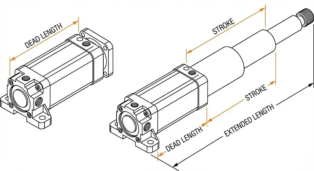
A four-way directional control valve typically has four main ports: Port P connects to the pressure oil source, Port T connects to the reservoir, and Ports A and B connect to both sides of the hydraulic cylinder. “Four-way” refers to the number of ports, not the number of operating positions. Common three-position four-way valves have three positions: extend, retract, and neutral.
Assuming Port A is connected to the rodless chamber and Port B is connected to the rod chamber, when P is connected to A and B is connected to T, the piston rod extends; when switched to P connected to B and A connected to T, the piston rod retracts. You can determine the action by following these two fluid paths, without having to memorize the direction of the valve handle or solenoid.
The fluid connection configuration in the neutral position is called the “neutral function,” which determines how the fluid flows after operation stops. For example, a series neutral typically connects P to T while closing A and B; a floating neutral connects A and B to the tank, allowing external forces to push the hydraulic cylinder. Even when A and B are closed, internal leakage may occur within the spool valve, so a closed neutral position should not be relied upon as a reliable load-holding measure. When selecting a valve, you should simultaneously verify the center position fluid path, the pump’s unloading requirements, and the allowable load displacement.
Meter-In vs. Meter-Out Flow Control
Meter-in flow control regulates speed by limiting the flow entering the hydraulic cylinder, while meter-out flow control regulates speed by limiting the flow exiting the cylinder. You can think of the former as controlling “how much oil is fed in” and the latter as controlling “how much oil is allowed to exit.”
Inlet throttling is suitable for situations where the load continuously resists movement, such as when a hydraulic cylinder pushes a slide block horizontally against a constant frictional resistance. If gravity or an external force actively drives the load, restricting only the inlet flow may not control the speed: the load may move faster than the oil supply can refill the chamber, resulting in insufficient oil supply, low pressure, and unstable motion.
Return flow throttling helps limit the movement of such loads by creating resistance on the return side, but it increases back pressure and heat generation, and may also cause the pressure in a particular chamber to exceed expectations. A standard throttle valve cannot replace the load-holding device required for suspended loads. You should first determine whether the load resists movement throughout its entire stroke or is likely to actively drive movement before selecting a speed control scheme.
During commissioning, it is recommended that you record the extension and retraction times separately under different load conditions. If the throttle opening remains constant but the speed changes significantly with the load, you need to check the pressure differential across the throttle orifice and evaluate whether to use a pressure-compensated flow control valve—a valve that helps stabilize flow by compensating for pressure changes.
Load-Holding and Counterbalance Valves
Load-holding valves are used to restrict the flow of hydraulic fluid out of the load-bearing chamber, helping hydraulic cylinders maintain their load after the oil supply is cut off. Common solutions include pilot-operated check valves and counterbalance valves, which serve different purposes.
A pilot-operated check valve allows fluid to flow in one direction and closes in the opposite direction, opening only when activated by control pressure. It is suitable for applications requiring static holding, such as maintaining the position of a fixture after it has stopped moving, but is not suitable for continuously adjusting the descent speed. A counterbalance valve can both hold the load and regulate fluid discharge under control pressure, making it suitable for situations where gravity might cause the load to descend on its own.
For example, when a vertical hydraulic cylinder supports a platform, you need to ensure that the platform does not descend on its own after stopping, nor does it suddenly accelerate due to its own weight during the descent. In this case, a balancing valve circuit should be evaluated, rather than relying solely on a directional control valve to close the oil port. Valve selection must also take into account load pressure, control oil pressure, return line backpressure, and the valve’s flow range; settings from other equipment cannot be directly applied.
During installation, priority should be given to mounting the load-holding valve directly on the hydraulic cylinder or as close as possible to the load port to minimize unprotected piping between the valve and the cylinder. However, this cannot eliminate all sources of displacement, such as internal leakage through piston seals; if personnel need to enter the space beneath a raised load for maintenance, mechanical support is also required.
End-of-Stroke Cushioning
End-of-stroke cushioning gradually restricts the oil discharge passage as the piston approaches the end of its stroke, causing the hydraulic cylinder to decelerate during the final portion of the stroke. You can think of it as a hydraulic deceleration process before reaching the end of the stroke, used to reduce the impact, noise, and vibration caused by the piston striking the end cap. It only acts in the end-of-stroke region and cannot replace speed control throughout the entire stroke.
If your equipment has a high moving mass or reaches the end of its stroke at a high speed, you should verify the cushioning’s energy absorption capacity. Considering only the kinetic energy of the moving parts, doubling the speed quadruples the kinetic energy; therefore, after increasing the operating speed, you must re-evaluate the cushioning capacity and cannot assume that the original settings remain valid.
For adjustable buffers, follow the manufacturer’s instructions to start with a lower speed and adjust gradually, then verify the settings under actual load and operating speed. If the buffer is too weak, noticeable impact may still occur; if it is too strong, it may cause the end-of-stroke movement to be too slow or result in high localized pressure. If the existing buffering capacity is insufficient, consider implementing early deceleration or an external buffering device rather than continuously tightening the adjustment screw.
Where Are Double Acting Cylinders Used?
Double-acting hydraulic cylinders are commonly used in construction machinery, material handling equipment, industrial presses, and positioning, steering, and clamping systems. A common requirement for these applications is that the equipment not only needs hydraulic pressure to push the load but also to return the load or overcome resistance in the opposite direction. If your equipment can reliably rely on gravity or springs for return travel, a single-acting hydraulic cylinder may also meet your requirements; you should not assume that a “double-acting” cylinder is more suitable simply because it is labeled as such.
Mobile Equipment and Material Handling
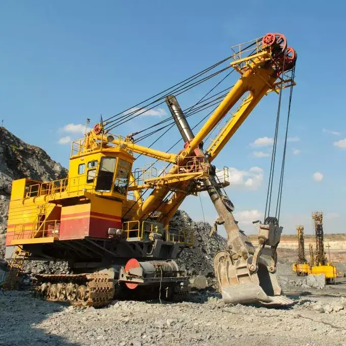
In construction machinery, double-acting hydraulic cylinders are commonly used for excavator dipper arm and bucket movements, loader bucket tilting, as well as the pushing, pulling, tilting, and clamping mechanisms of material handling equipment. These movements require reciprocating motion under varying loads and orientations and cannot always rely on gravity for return. Manufacturers of hydraulic cylinders for mobile equipment offer both single-acting and double-acting designs to accommodate different motion requirements.
For example, a loader’s bucket must tilt backward to retain material and forward to unload it. A double-acting hydraulic cylinder can actively drive movements in both directions via a linkage mechanism. However, whether cylinder extension corresponds to bucket loading or unloading depends on the specific mechanism and cannot be determined solely by the direction of the piston rod.
When selecting a cylinder, you should examine the force conditions across the entire range of motion, particularly at the most unfavorable link angles. For materials of the same weight, different hydraulic cylinder thrusts may be required at different mechanical angles. A common mistake is selecting a cylinder based solely on load weight while ignoring changes in the lever arm caused by the linkages, as well as operational impacts and off-center loads.
Also, do not categorize all lifting and lowering motions as double-acting applications. Certain lifting mechanisms that rely on the load’s own weight for descent can use single-acting hydraulic cylinders; double-acting designs are more appropriate when active retraction, bidirectional force application, or the inability to rely on gravity for the return stroke are required.
Industrial Presses and Production Machinery
Double-acting hydraulic cylinders can be used for press-fitting, forming, shearing, and material feeding and ejection operations on production lines. They are suitable for equipment that requires both output force during the working stroke and active retraction. For example, after a press head completes a press-fitting operation, if the return process requires overcoming guide friction or workpiece separation resistance, a hydraulically driven return stroke is more likely to meet the requirements than relying solely on springs.
You can break down a press-fitting cycle into three stages—rapid approach, force application, and return—and then determine the required force, speed, and stroke for each stage separately. Do not substitute no-load reciprocation time for the actual production cycle time, nor should you verify only the press-fitting thrust while ignoring the return pull force. Standard single-rod double-acting hydraulic cylinders have a smaller effective area during retraction; at the same pressure, the theoretical pull force is typically lower than the thrust.
For presses, the frame and guide mechanisms should also bear eccentric loads to prevent the piston rod from doubling as a lateral guide for the press head. If your application involves light loads, or if cleanliness and programmable positioning are priorities, you may also want to consider pneumatic or electric actuators; double-acting hydraulic cylinders are not the default choice for all production operations.
Positioning, Steering, and Clamping Systems
In positioning systems, double-acting hydraulic cylinders can move slides, stop mechanisms, or adjustable brackets in both directions. However, “bidirectional drive” alone does not guarantee high-precision positioning. If you need to repeatedly stop at a specified position midway through the stroke, you typically also need position sensors and closed-loop control—that is, measuring the actual position and adjusting the motion based on the deviation, rather than relying solely on the duration of oil flow to determine the position.
In steering systems, hydraulic cylinders drive steering linkages by extending and retracting, causing the wheels or articulated mechanisms to turn in either direction. Some steering applications use a double-rod configuration; when the diameters of the piston rods on both sides are the same, the effective areas on both sides are equal, which helps achieve nearly identical force and speed characteristics in both directions. Specific steering performance still depends on the oil supply and linkage geometry; the two directions of a standard single-rod cylinder cannot be directly considered equivalent.
In clamping systems, double-acting hydraulic cylinders can actively perform clamping and release operations, making them suitable for mechanisms where spring return is insufficient to ensure reliable release. Double-acting clamping cylinders and angular clamping elements provided by manufacturers are specific examples of such applications.
You should first confirm whether the fixture clamps when the piston rod extends or when it retracts, then verify the clamping force based on the corresponding effective area, while also considering the force transmission relationship of the lever mechanism. Another common misconception is the assumption that the fixture will definitely not release once the oil supply is stopped; when continuous clamping force is required, appropriate pressure-holding or mechanical locking measures should be configured based on leakage, the state after pressure loss, and the workpiece requirements.
When Should You Choose Double Acting Over Single Acting?
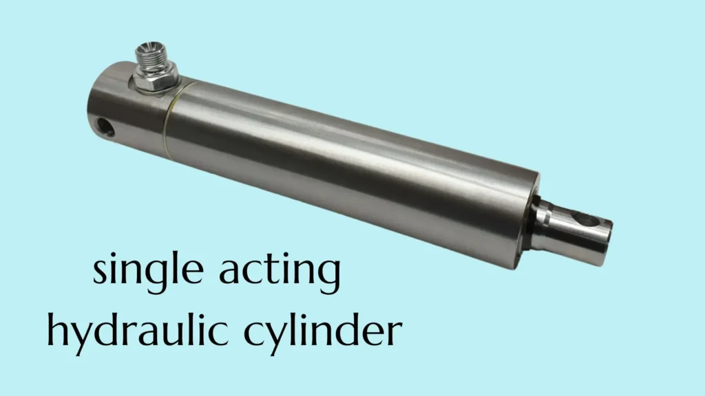
When your equipment requires active force in both directions, or when gravity or springs cannot reliably complete the return stroke, you should prioritize double-acting hydraulic cylinders. The key considerations are whether there is sufficient power for the return stroke and whether the load and cycle time requirements can be met. If the equipment only requires hydraulic force in one direction and an external force can reliably complete the return stroke, a single-acting hydraulic cylinder typically offers a simpler solution.
Powered and Controlled Return Requirements
If the return process also requires pulling the load, overcoming friction, or disengaging the mechanism from the workpiece, a double-acting hydraulic cylinder is generally more suitable. It uses pressurized oil to drive the return stroke, reducing reliance on spring force and the load’s own weight, and makes it easier to adjust the return motion via the hydraulic circuit.
For example, after a press-fitting mechanism completes its task, the press head may need to overcome the workpiece’s engagement resistance to retract. In this case, you need to verify the retraction pulling force, rather than simply confirming the extension thrust. For standard single-rod double-acting hydraulic cylinders, the pressure-receiving area on the retraction side is smaller, so the theoretical pulling force at the same pressure is typically lower than the thrust.
A practical method for evaluation is: Check whether the minimum available return force throughout the entire return stroke is still greater than the maximum return resistance. For single-acting configurations, consider the thrust exerted by springs at different positions, the actual available gravitational force, and the resistance generated by seal friction and return line backpressure. If full return cannot be guaranteed, or if the return time fails to meet production requirements, a double-acting configuration should be considered.
However, the “need to control return speed” does not necessarily mean a double-acting cylinder must be used. A single-acting system with gravity-assisted return can also regulate the descent speed through appropriate flow and load control components; the key is whether the external return force is always sufficient.
Overrunning or Horizontal Loads
An overrunning load occurs when gravity or an external force actively drives the mechanism’s movement, causing the load to tend to move faster than the speed supported by the hydraulic supply. For example, a heavy object may pull the piston rod downward on its own as it descends; certain tilting mechanisms, after passing a specific angle, may also transition from “requiring a push” to “requiring movement to be restricted.”
If your load direction varies with the mechanism’s position, a double-acting hydraulic cylinder facilitates active drive in both directions. However, it cannot prevent load runaway on its own; load control components such as balancing valves must still be configured according to operating conditions to limit the discharge from the load-bearing chamber. Replacing the cylinder with a double-acting model does not replace the need for descent control and load-holding design.
For horizontal motion, gravity typically cannot directly assist the piston rod in returning. For example, a horizontal material-pushing mechanism must both push the material out and actively retract the push plate; if there is no reliable spring or external return mechanism, a double-acting configuration is generally more suitable. However, horizontal installation does not preclude the use of a single-acting cylinder: as long as a spring or external mechanism can overcome the resistance over the full stroke, it can still be used.
Before selecting a cylinder, you should check the load direction at the starting point, midpoint, and near the end point, paying particular attention to positions where the mechanism inverts or the lever arm changes significantly. Do not base your decision solely on whether the installation is “horizontal” or “vertical”; instead, confirm exactly which component provides the driving force and which limits the speed for each segment of the motion.
Precision, Duty Cycle, and Circuit Complexity
When equipment requires frequent reciprocating motion, separate speed control in both directions, or return movements at a fixed cycle rate, double-acting hydraulic cylinders are generally easier to control. However, they do not automatically provide high positioning accuracy. If you require the piston rod to repeatedly stop at a specific intermediate position, you will typically need a position sensor and closed-loop control—that is, measuring the actual position and adjusting the motion based on the deviation.
When evaluating a work cycle, do not focus solely on “how many times per minute the cylinder moves.” You should also record the time required for extension, load hold, retraction, and idle, as well as the duration of continuous operation. There is no fixed frequency threshold that applies to all hydraulic cylinders; seals, operating speed, oil temperature, and system cooling must all be considered together.
For example, suppose production requirements mandate that the feed mechanism return within two seconds; this is a design requirement, not a test result. You should verify the return time within the specified load and oil temperature ranges. If a single-acting configuration consistently meets the requirements, there is no need to change the design solely for the sake of “greater speed”; however, if spring-assisted return stalls at certain positions or return times fluctuate significantly, a double-acting configuration warrants consideration.
Adopting a double-acting configuration typically requires connecting two working oil ports and using a control circuit capable of switching the flow of oil between the two sides; this also increases piping and commissioning work. Therefore, you should weigh the benefits of reliable return travel, bidirectional force application, and cycle time control against the increased system costs, rather than assuming by default that a double-acting system is necessarily more precise, durable, or energy-efficient.
What Must Be Specified for Reliable Operation?
To ensure reliable operation of a double-acting hydraulic cylinder, you need to specify the load, speed, and stroke in both directions, as well as the actual available pressure and flow rate, before determining the size, mounting method, and seal configuration. Providing only the “bore, stroke, and maximum pressure” is usually insufficient for selecting the right cylinder. Hydraulic cylinders of the same size may have different performance characteristics depending on the mounting angle, operating frequency, and fluid temperature.
Bore, Rod Diameter, Stroke, and Working Pressure
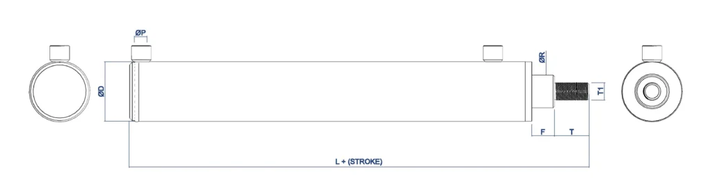
The bore is the internal diameter of the cylinder barrel and determines the piston’s pressure-receiving area; the rod diameter affects the retraction force and also influences the rod’s ability to withstand thrust loads. You cannot simply increase the bore to achieve greater thrust; you must also verify that the rod can withstand this force, especially during long strokes and when fully extended.
Long piston rods may buckle under compression—that is, lose stability in the same way a slender rod bends under pressure. Therefore, the rod diameter must be determined based on the maximum thrust, extension length, and mounting support configuration; it should not be selected solely based on connection threads or existing mounting holes. The manufacturer’s buckling calculations also take into account the mounting method and piston rod material.
Stroke is the distance the piston rod can travel. You should provide the required working stroke, the installation dimensions when fully retracted, and the space constraints when fully extended. If a link mechanism is present, you must also verify the relationship between the hydraulic cylinder’s stroke and the actual travel distance of the equipment, as the two are not necessarily equal.
Regarding pressure, a distinction should be made between normal operating pressure, potential peak pressure, and the hydraulic cylinder’s allowable pressure. Do not mistake the pressure test rating for continuous operating pressure, nor assume that the relief valve at the pump outlet can limit all local pressures; during return flow throttling or deceleration, pressure amplification may occur in the rod chamber, requiring separate verification.
Required Push and Pull Force
You need to specify the maximum extension thrust and maximum retraction pull force separately, and indicate whether the load involves impact, acceleration, or changes in mechanical angle. The load weight does not directly represent the force required by the hydraulic cylinder, as guide rail friction, link arm lengths, and acceleration requirements will all alter the actual demand.
For a standard single-rod, double-acting hydraulic cylinder, when friction is neglected, the more complete calculation formula is: Extension force = non-rod chamber pressure × piston area – rod chamber pressure × annular area; Retraction force = rod chamber pressure × annular area – non-rod chamber pressure × piston area. The annular area is the piston area minus the cross-sectional area of the piston rod. Simplifying the equation to “inlet pressure × effective area” is appropriate only when the pressure on the return side can be neglected.
For example, assuming a cylinder bore of 80 mm, a rod diameter of 45 mm, a non-rod chamber pressure of 160 bar, and a return backpressure in the rod chamber of 10 bar, the theoretical net extension force is approximately 77.0 kN, while ignoring the backpressure yields approximately 80.4 kN. This is an example of size and pressure calculation; it does not account for seal friction and does not represent a guaranteed product output.
When selecting a cylinder for actual use, you should verify both directions under the most unfavorable operating conditions and determine the safety margin based on load fluctuations, shock loads, and operating frequency. A common mistake is to check only the maximum extension thrust; as a result, the equipment may be able to push the workpiece out but lack sufficient pulling force to complete the return stroke.
Target Speed and Available Flow
You should determine the target speeds for extension and retraction separately, and specify whether different speeds are used for rapid approach, working motion, and end-of-stroke deceleration. The required flow rate for a hydraulic cylinder is calculated using the formula “Flow Rate = Speed × Effective Area of the Corresponding Chamber”; you cannot determine whether the motion is fast enough based solely on the pump’s nameplate flow rate.
For example, consider a hydraulic cylinder with a bore diameter of 80 mm and a rod diameter of 45 mm. Assuming a speed of 100 mm/s is required in both directions and neglecting leakage, the required inflow rate for extension is approximately 30.2 L/min, and for retraction, approximately 20.6 L/min. However, during retraction, the flow discharged from the rodless chamber remains approximately 30.2 L/min; therefore, the return line cannot be selected based solely on 20.6 L/min.
You also need to confirm how much flow the system can actually allocate to this hydraulic cylinder at the required operating pressure. If multiple actuators operate simultaneously, or if the pump is power-limited, the available flow may be lower than expected. While increasing the cylinder bore diameter can increase thrust, it will also reduce speed if the flow rate remains constant.
When providing specifications, it is recommended to also specify the number of cycles per minute, continuous operating time, and dwell time. This allows for an assessment of whether the valve’s flow capacity, sealing speed range, and system heat dissipation are adequate—rather than merely confirming that the hydraulic cylinder can complete a single stroke.
Mounting, Side Load, Seals, and Fluid Compatibility
The mounting method must align with the mechanism’s motion path. For fixed linear motion, a suitable fixed mounting can be used; if the hydraulic cylinder requires swiveling during operation, consider mounting configurations that allow rotation, such as mounting brackets or swivel bearings. You should provide installation drawings, pin dimensions, and the range of swing to avoid forcing the piston rod to bend to accommodate the mechanism after installation.
Lateral loads are forces perpendicular to the piston rod axis and increase wear on guide components and seals. Standard hydraulic cylinders are primarily designed to withstand axial thrust and pull; lateral forces on a slide block or ram should typically be borne by independent guide rails. If lateral loads cannot be avoided, the manufacturer must perform a calculation; simply increasing the piston rod diameter is not a sufficient solution.
When selecting seals, you must provide the specific name or model of the hydraulic fluid, the minimum and maximum oil temperatures, operating speed, and environmental conditions. Simply writing “hydraulic oil” is insufficient: seal configurations suitable for mineral hydraulic oils may not be suitable for other media, such as water-glycol. Manufacturers will also provide different seal material configurations based on the medium.
For example, in dusty outdoor environments, dust seals and piston rod protection must be considered; in environments with flushing water or corrosive conditions, surface corrosion protection measures must also be confirmed. When requesting a quote, include installation drawings, fluid specifications, and temperature ranges; this is more helpful in determining a reliable configuration than simply requesting “better seals.”
Frequently Asked Questions About Double Acting Hydraulic Cylinders
Can a Double-Acting Cylinder Be Used as a Single-Acting Cylinder?
Some double-acting hydraulic cylinders can be used in a single-acting configuration, but the manufacturer must confirm that the design and circuit are suitable. You need a reliable gravity-fed, spring-loaded, or externally driven mechanism to complete the return stroke, and you must provide appropriate drain, refill, or filtered vent lines for the unpressurized side. Do not directly plug the other port, as this may trap fluid, obstruct movement, or create abnormal pressure; nor should you leave the port open to allow contaminants to enter.
Why Does a Double-Acting Cylinder Retract Faster?
In a standard single-rod double-acting hydraulic cylinder, retraction is typically faster when the actual oil flow rate is the same in both directions. This is because the piston rod occupies a portion of the cross-sectional area, so the rod chamber requires less oil to complete the same stroke. According to the formula “speed = flow rate ÷ effective area,” the smaller the area, the faster the speed. However, if you adjust the flow rates for the two directions separately or use a special circuit, retraction may not necessarily be faster.
Does a Double-Acting Cylinder Need a Four-Way Valve?
A four-way directional control valve is typically used, but it is not necessarily required to use a single, standalone four-way valve. In a conventional circuit, oil is supplied through port P and returns through port T, while ports A and B connect to both sides of the hydraulic cylinder to achieve alternating pressurization and return; alternatively, multiple valves can be combined to form a control circuit with the same functionality. What you need to confirm is that the fluid path can switch correctly, rather than simply counting the number of valves. Additionally, “four-way” refers to four main ports, not four operating positions.
What Happens If the Two Hoses Are Reversed?
In a circuit where a standard directional control valve is directly connected to a hydraulic cylinder, reversing the two working hoses will typically cause the direction of motion to be opposite to the original control command. An extension command will result in retraction, and the corresponding output force and speed may also change. If the circuit includes a balancing valve, a pilot-operated check valve, or a check-throttling element, reversed connections may also cause movement to be blocked or result in abnormal load control. You should verify the connections against the hydraulic schematic and support the load, release the system, and relieve residual pressure in the oil chambers before making any adjustments.
Work with a IATF 16949 Certified Blind Rivet Manufacturer
Get High Quality Rivets Instead of Huck and Avdel Rivets
Explore Rivmate Cases

Hey There, I'm Melody!
We are a hydraulic cylinder manufacturer. For over 20 years, we have focused on producing reliable hydraulic cylinders. Need a hydraulic cylinder solution? Feel free to contact us.