Home / How to Fix a Leaking Hydraulic Cylinder and Prevent Future Leaks
How to Fix a Leaking Hydraulic Cylinder and Prevent Future Leaks
- Author: GY Hydraulic
- 20+ Years of Manufacturing
To repair a hydraulic cylinder leak, you must first identify the location of the leak, then inspect the seals and mating parts. Once the damage has been repaired, reassemble the cylinder and verify the results through leakage and functional tests. If the leak originates from an external fitting, it may be sufficient to simply address the connection; if it originates from inside the hydraulic cylinder, further assessment is required to determine whether disassembly and overhaul are necessary. To prevent the leak from recurring, the root causes—such as hydraulic fluid contamination, misalignment during installation, or abnormal pressure or temperature—must also be addressed.
This GY Hydraulic guide will help you understand the rationale behind each step. The content focuses primarily on common, serviceable piston-type hydraulic cylinders. Multi-stage telescopic cylinders and hydraulic cylinders with built-in valves or position sensors require supplementary maintenance documentation. Specific disassembly and assembly sequences, tightening torques and test conditions should be based on the manufacturer’s documentation for the relevant model; beginners can use this as a guide to identify problems and prepare materials, whilst tasks involving pressure relief, heavy-load lifting and pressure testing should be carried out by trained personnel.
Table of Contents
Confirm Whether the Leak Is External or Internal
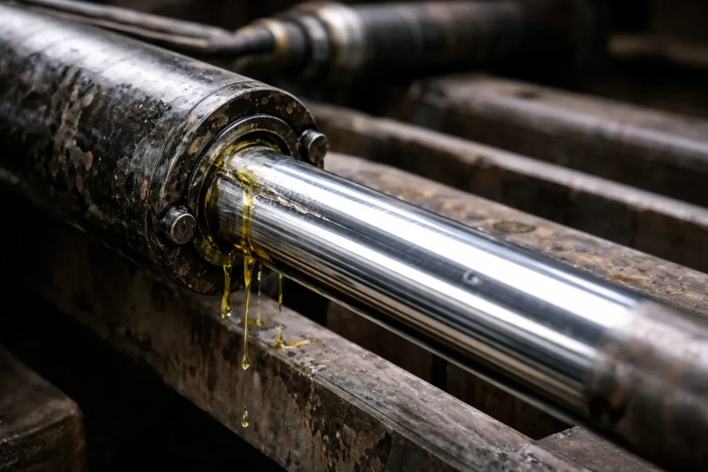
To distinguish between external and internal leakage, first consider where the fluid is going. External leakage occurs when fluid flows from a hydraulic cylinder or connection point to the outside of the equipment; it is commonly found at the piston rod outlet, end cap joints, port connections and hoses. The piston rod is the metal rod that extends and retracts. Internal leakage in a hydraulic cylinder typically refers to fluid passing through the piston seal, flowing from the chamber under higher pressure to the chamber under lower pressure; the piston seal is a component used to separate the fluid on either side of the piston. This type of leakage does not necessarily leave external oil stains.
You should first note the locations of any existing oil stains, then remove the old oil after safely shutting down the equipment and relieving the pressure. If the condition of the equipment permits a safe test run, have the operator perform the prescribed operations as per the manual, then shut down the equipment, relieve the pressure and re-inspect to identify where new oil first appears. For example, oil leaking from a fitting may run down the cylinder body to the base of the end cap, whilst the actual leak point is not on the end cap itself. Do not rely solely on the location of the final oil drop to make a judgement, and under no circumstances should you search for the leak point by hand whilst the system is under pressure.
If the exterior is dry but the equipment is unable to hold its position, you must investigate internal leaks. The term ‘drift’ here refers to the piston rod continuing to move slowly in the absence of any movement command. **Drift is a clue, but it does not, on its own, prove that the piston seal is damaged. ** Directional control valves, which regulate the flow of hydraulic fluid, or load-holding valves, which prevent the load from dropping unaided, may also be leaking internally. For example, when a lifting mechanism descends slowly, one should first distinguish between faults in the hydraulic cylinder and those in the valve assembly before deciding whether to dismantle the cylinder. To confirm internal leakage within the cylinder, a qualified technician must isolate the relevant circuits in accordance with the model specifications and carry out tests.
Safely Isolate, Depressurize, and Remove the Cylinder
Stopping the pump does not mean that the hydraulic cylinder is completely depressurised. The load, closed oil circuits and accumulators may all retain energy; an accumulator is a device that stores hydraulic energy and releases it when required. Before dismantling, the working equipment must be lowered to a safe position in accordance with the equipment procedures, supported by mechanical supports of suitable rated capacity, and then the electrical supply, engine and other power sources must be isolated. For equipment requiring lockout and tagout, the relevant isolation procedures must be completed to prevent accidental start-up by others.
Depressurisation must cover all oil chambers and lines you intend to access. A main pressure gauge reading zero does not confirm that the cylinder chamber sealed by the load-holding valve has also been depressurised. Maintenance personnel should verify this by referring to the hydraulic schematic diagram and using the specified depressurisation routes and pressure measurement points. Do not rely on loosening fittings to ‘check if there is still pressure’, nor tap the valve spool inside a quick-release coupling to drain oil.
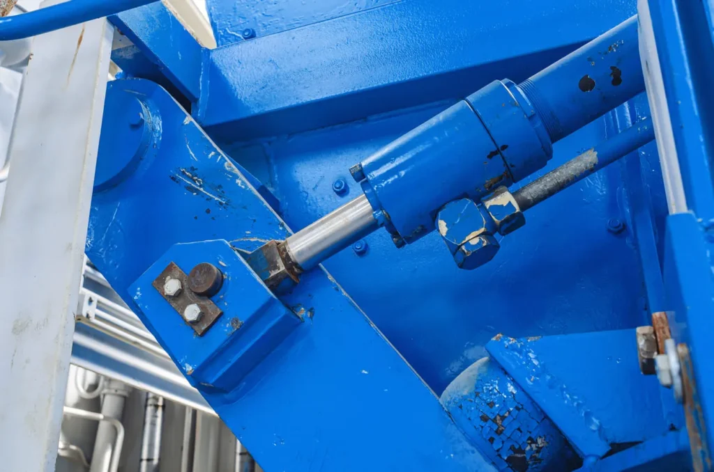
Before removing any pipework, take photographs and mark each oil hose against its corresponding port, collect any residual oil, and then protect the openings with clean, suitable plugs. Before removing a pin, use suitable lifting equipment to support both the hydraulic cylinder and the connected mechanisms separately, ensuring that the pin is no longer bearing any load. For example, when removing or installing a loader’s lift cylinder, the fact that the bucket has been lowered to the ground does not automatically mean that all linkages are securely fixed; the support requirements in the machine’s manual must still be followed. Never hook slings onto the piston rod coating, hoses or sensors.
High-pressure oil flow can penetrate the skin; wearing ordinary gloves does not make contact with pressurised fluid a safe operation. If you suspect an oil injection injury, even if the wound is very small, seek medical attention immediately and specify that hydraulic oil is involved.
Clean, Mark, and Prepare the Cylinder for Disassembly
Before disassembly, thoroughly clean off any external dirt and prepare a clean work area large enough to accommodate the entire piston rod assembly. If mud or sand enters the cylinder via the end cap, it may cause the newly fitted seals to fail prematurely. Use cleaning products compatible with the parts and seal materials, lint-free wiping materials, and a clean oil collection container; do not use old, fraying rags to plug the oil ports, and ensure that no cleaning fluid or external contaminants enter the cylinder.
Apply removable directional markings to non-mating, non-sealing surfaces, and record the relative positions of the end caps, cylinder barrel and mounting lugs. The cylinder barrel is the tube that houses the piston’s movement. When removing each set of components, photograph the arrangement and orientation of the seals, and arrange them in sections according to the order of disassembly. For example, even if two hydraulic cylinders on the same piece of equipment have similar external dimensions, they should be numbered separately to avoid mixing up pistons, guide components or repair kits.
Have the assembly drawings, seal list and tightening specifications for this model ready before selecting tools. Threaded end caps may require a matching pin-hole spanner, whilst snap-ring assemblies may require the appropriate snap-ring tool; clamping and support devices should be chosen to avoid denting the cylinder barrel or piston rod. If it is not yet confirmed how the end cap is secured, do not apply force prematurely. Photographs of the old seals can aid verification, but the final installation must be carried out in accordance with the correct drawings, as the previous repair may itself have been carried out incorrectly.
Disassemble the Cylinder Without Damaging Components
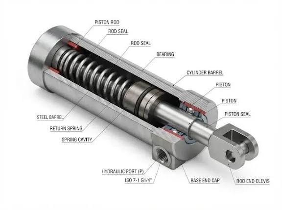
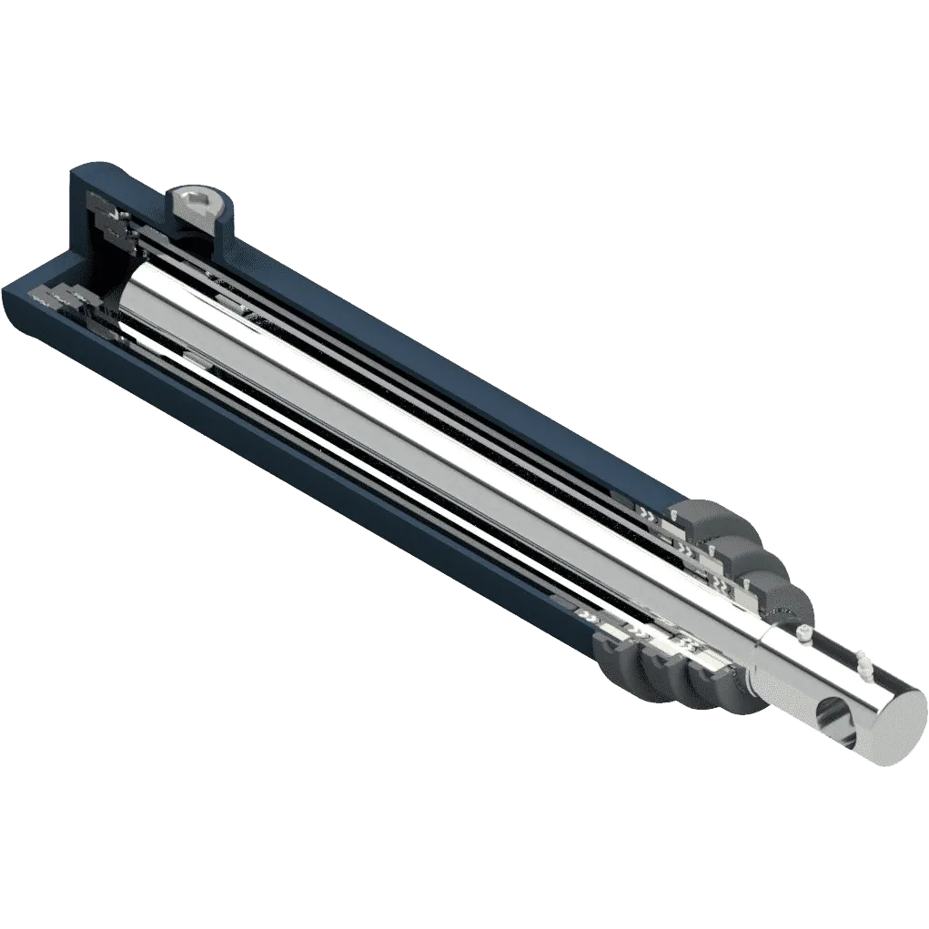
First identify the mounting configuration, then decide on the disassembly method. Common hydraulic cylinders may utilise threaded end caps, tie-rod fastenings, snap rings or wire retaining rings. A tie-rod is a long bolt connecting both ends along the outer surface of the cylinder body; a retaining ring is a component that restricts the axial movement of parts. These configurations cannot be opened in the same way. The term ‘welded hydraulic cylinder’ does not necessarily mean that the cylinder barrel must be cut open; some designs still allow for maintenance via removable rod-end assemblies.
After thoroughly depressurising the system and draining any residual oil, release the locking screws, retaining rings or other retaining devices in accordance with the maintenance documentation. For designs requiring the end cap to be ejected, use the ejection holes or removal tools provided in the design; do not insert a screwdriver between the sealing surfaces to pry it open. For designs featuring springs, position sensors or special locking mechanisms, first ascertain the specific handling requirements; if you encounter unexplained resistance, stop and check for hidden retaining components rather than extending the wrench to continue tightening.
When extracting the piston rod assembly, use a support or lifting device to keep it roughly aligned with the cylinder bore axis, preventing the long rod from sagging and the piston edge from scratching the inner wall. Do not use compressed air to ‘blow out’ the assembly, nor use pipe wrenches to grip the working surface coating. When removing old seals, use suitable seal removal tools to protect the base and edges of the seal groove; even a single scratch on the base of the groove could become a pathway for oil leakage in the future.
Not all piston-to-piston rod connections can be unscrewed directly. If the drawings specify that the connection is non-serviceable, or if a specialised unlocking procedure is required, the assembly should be retained or handed over to a specialist repair workshop for handling.
Inspect the Rod, Tube, Piston, Gland, and Bearings
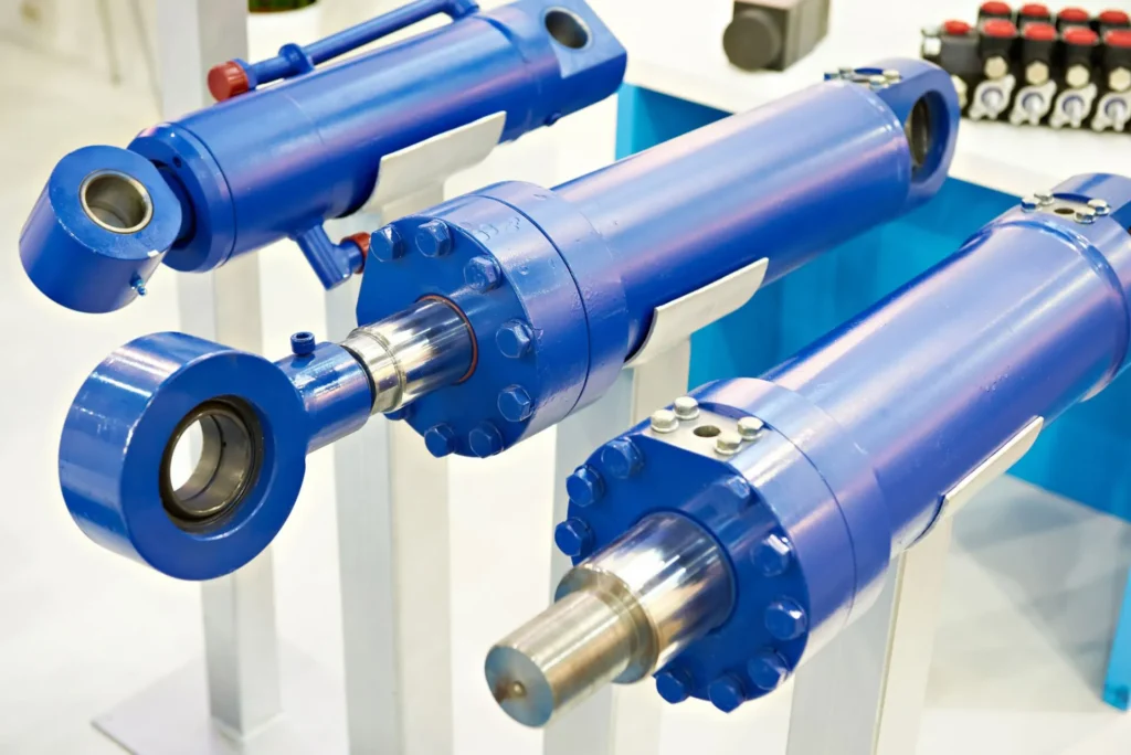
The aim of the inspection is to determine whether the component can still provide a suitable working surface and support for a new seal. The piston is a component that moves back and forth within the cylinder barrel whilst withstanding hydraulic pressure. The guide sleeve (gland) is usually located at the end of the rod; it houses the rod seal and, in conjunction with the guide assembly, supports the piston rod. The bearings referred to here are typically sliding sleeves or wear-resistant guide rings, whose function is to help keep moving parts centred and to reduce direct metal-to-metal contact.
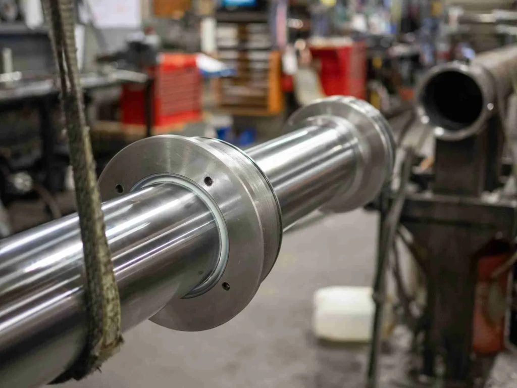
First, check the piston rod’s effective stroke for any longitudinal scratches, pitted rust, flaking of the plating or signs of bending. Next, inspect the inner wall of the cylinder for scoring, corrosion and localised abnormal wear. Whilst visual inspection can reveal obvious damage, it does not guarantee dimensional compliance; maintenance personnel should measure the rod diameter, cylinder bore and relevant geometric deviations in accordance with the drawings. Geometric deviations include roundness and straightness—that is, whether the component is sufficiently round and straight. A shiny surface does not necessarily mean the component is suitable for continued use with new seals.
Next, inspect the seal grooves, threads, retaining structures and guide components on the piston and guide sleeves to determine whether there is any looseness, deformation or excessive clearance. For example, if repeated scuff marks appear on one side of the piston rod whilst the guide ring is also severely worn on the same side, one should suspect misalignment during installation or lateral loads, rather than simply seal ageing. Lateral loads are forces acting perpendicular to the extension and retraction direction of the hydraulic cylinder; seals cannot bear these loads in place of the guide components.
It is recommended that records comprising the following four items be maintained for each critical component: ‘photographs of damage, measured dimensions, drawing tolerances and remedial decisions’. Where there is no specific model reference, do not arbitrarily apply general scratch depth or clearance limits; if cracks, obvious bending or deformation of load-bearing components are discovered, a professional assessment should be carried out first.
Select and Install the Correct Seal Kit
The correct seal kit must be compatible with the design, dimensions, hydraulic fluid and operating conditions. Prioritise confirming the repair kit using the model number, serial number and drawing version on the hydraulic cylinder nameplate, then cross-check the cylinder bore, rod diameter and seal configuration. The cylinder bore is the working internal diameter of the cylinder barrel. Knowing only the cylinder bore is usually insufficient to determine the complete seal set, as the rod diameter, seal grooves and design version may vary.
If there is no traceable kit number, the supplier should confirm the specifications based on the parts drawing and actual measurements of the seal grooves; the old seals should only be used as a supplementary reference, as they may have worn, expanded or become deformed. In addition to dimensions, the specific grade of hydraulic fluid, operating temperature, pressure and movement speed must also be provided. For example, if a system has been converted from mineral hydraulic oil to a water-glycol fire-resistant fluid, it cannot be assumed that the original seal materials remain suitable; material compatibility must be re-checked. Even if the material names are identical, this does not imply that the application ranges of different formulations are entirely consistent.
Prior to installation, damaged components must be repaired and re-inspected, whilst the seal grooves and oil passages must be cleaned and found to be in good condition. Confirm the positions of the rod seals, piston seals, dust seals and support rings in accordance with the assembly drawing: dust seals are used to block external contaminants, whilst support rings are used to reduce the risk of seals being forced into the gap by pressure. Neither should be confused with wear rings, which serve a guiding function.
Determine the installation direction according to the seal design; do not assume that all seals are intended to be installed with the ‘opening facing inwards’. Use installation protection sleeves when passing through threads and sharp edges, and lubricate with clean working fluid or an assembly lubricant confirmed to be compatible. For seals requiring expansion, compression or shaping, use the appropriate tools and processes; do not use open flames, arbitrary heat treatment or excessive stretching to force installation.
Repair Surface Damage and Correct the Root Cause
Before the new seal is formally fitted, any surface damage or mechanical issues identified during inspection must first be rectified. The aim of surface repair is to restore the specified dimensions, shape and surface quality; it is not simply a matter of grinding away scratches until they are no longer visible. Surface roughness is an indicator of subtle surface irregularities, which can affect the oil film and the contact condition of the seal; neither excessive roughness nor excessive polishing beyond the design specifications should be regarded as a substitute for a satisfactory repair.
Whether minor defects can be addressed locally must be determined by maintenance personnel familiar with the component, in conjunction with the technical drawings. Deep corrosion, plating peeling or bending of the piston rod may require specialist repair or replacement; damage to the inner wall of the cylinder may necessitate honing, i.e. the use of precision grinding to improve the internal surface finish and shape of the bore. Regardless of the machining method employed, it must be confirmed that the dimensions and seal fit after treatment still meet the requirements. Do not grind the rod with a hand-held grinder, nor use adhesive to fill the sealing contact surfaces as a substitute for a proper repair.
Next, correlate the damage with the actual operating conditions. In the case of unilateral wear, check the installation alignment, pins and hinged joints; if the sealing edges are crushed, verify the clearance, support configuration and abnormal pressures; if the seal has hardened, lost its elasticity or expanded abnormally, check the temperature and fluid compatibility. These phenomena serve as guidelines for troubleshooting; one must not identify a single cause based solely on visual inspection.
For example, if a damaged dust seal continues to allow sand particles to enter the cylinder, simply replacing the main seal may still result in repeated scoring. Following repair, effective dust protection must be restored, and contaminated oil, filters and affected pipework must be treated in accordance with equipment specifications. Filtration precision and oil cleanliness targets must be derived from equipment requirements; filter elements should not be replaced arbitrarily merely to achieve ‘finer filtration’.

Reassemble, Reinstall, and Bleed the Cylinder
Before reassembly, check the parts list item by item to ensure that no old seals, tools or cleaning materials have been left behind. When installing the piston rod assembly, maintain axial alignment and protect the bores and edges through which the seals pass; if resistance increases suddenly, stop immediately to check whether the seal has been crimped or twisted, or whether the guide ring is misaligned. Do not force misaligned components into place by striking them with a hammer or tightening the end cap.
The piston locking mechanism, end caps, tie rods and retaining components must all be reinstalled in accordance with the sequence, torque specifications and tightening methods specified for this model. Torque refers to the rotational force applied during tightening; tighter is not necessarily better. Disposable locking components that require replacement must not be reused, nor should threadlocker be applied unless specifically required. When reassembling the equipment, connect the oil lines in accordance with the original markings, check the alignment of the pin retainers and ensure correct installation, taking care not to kink or overstretch the hoses.
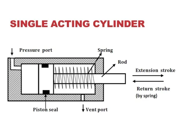
The purpose of bleeding is to remove free air from the cylinder, thereby reducing stroking, instability and localised compression heat. First, confirm the fluid level and circuit connections, then select the bleeding method in accordance with the manual. For designs with dedicated bleed ports, use the specified bleed equipment and procedures; for designs permitting bleed via circulation, carry out the procedure only within the permitted stroke, at low speed and under the specified low-pressure conditions. Certain single-acting cylinders lack the ability to retract actively and therefore cannot follow the reciprocating method used for double-acting cylinders.
For example, where the position of the bleed port is unsuitable, repeated extension and retraction may not necessarily expel air accumulated at higher levels; this should be addressed by maintenance personnel in accordance with installation requirements. Do not loosen fittings whilst under pressure, nor should you continuously hold the cylinder at the end of its stroke for the purpose of bleeding. If operation remains abnormal or foaming persists in the reservoir, suspend further loading and check for sources of air ingress, rather than continuing rapid cycling.
Pressure-Test and Check the Repair for Leakage
The fact that ‘no oil leaks are observed immediately after assembly’ does not mean that the repair has been successfully completed. Verification typically requires a distinction to be made between low-pressure functional checks, external leakage checks under specified conditions, and any necessary internal leakage or position-holding tests. Whether pressure testing is also required should be determined by the manufacturer or an approved repair test procedure. Pressure testing is intended to verify pressure-bearing capacity and must not be confused with observations made under normal operating pressure.
Prior to testing, ensure that fixings, hoses, couplings, gauges and protective measures are all suitable for the specified test conditions, and that the system has been fully vented. First, check operation and connections at the specified low pressure, then have a qualified technician gradually increase the pressure in accordance with the procedure. Test pressure, dwell time and permissible leakage rates must comply with the requirements for that specific model; a uniform application of ‘a certain multiple of the rated pressure’ is not permitted. Should any abnormal displacement, sudden leakage or structural deformation be detected, the test must be halted and an inspection carried out after the system has been fully depressurised. As pressure testing carries risks of fittings becoming dislodged, hoses whipping about and fluid ejection, the test area must be cordoned off.
Record the test pressure, oil temperature, holding time, piston position and observations regarding leakage. When checking for internal leakage, it must also be specified whether the test boundaries include the valve assembly; otherwise, it will be impossible to distinguish between leakage in series within the hydraulic cylinder and internal valve leakage. For example, a single successful lifting operation merely indicates that the equipment completed the movement under the conditions at that time; it cannot replace a position-holding check or internal leakage measurement.
Once the test has been passed, resume operation in accordance with the requirements for the complete unit, and retain observation records taken at both cold and normal operating temperatures. Subsequent routine inspections should focus on checking the original leakage points, new connections and the surface of the piston rod. Whether a thin oil film is permissible should be determined based on the specific design; persistent oil accumulation, dripping or the recurrence of previous performance anomalies all require re-inspection.
When to Rebuild, Replace, or Use a Professional Repair Shop
If the main pressure-bearing components and critical fit dimensions are within specification, and the faults are confined to seals and a small number of replaceable wear parts, a rebuild may usually be considered. In this context, a rebuild refers to the process of dismantling, measuring, restoring necessary components, replacing the relevant wear parts and carrying out testing; it is not merely a matter of fitting a new set of seals. For example, if the guide ring is worn but the cylinder barrel, piston rod and seal grooves are still within specification, the component may be worth repairing.
If the cylinder barrel is severely deformed, critical load-bearing areas are cracked, the piston rod is severely damaged, or if the correct fit cannot be restored despite multiple repairs, replacement should be assessed. When making a comparison, one must take into account the costs of parts, machining, testing, downtime and the consequences of a subsequent failure; it is not advisable to consider only the price of the repair kit. There is no fixed threshold applicable to all hydraulic cylinders stating that ‘replacement is mandatory if repair costs exceed a certain percentage of the cost of a new cylinder’.
Where re-plating and precision grinding, cylinder barrel machining, structural repairs, specialised assembly or high-precision leakage testing are required, the work should be entrusted to a repair workshop with the appropriate capabilities. Professional services should also be prioritised where safety-critical functions such as lifting and load-holding are involved, or where drawings, reliable tooling and testing facilities are lacking. When selecting a repair workshop, you should request that they provide a damage assessment, key measurement results, traceability information for parts and final test records, rather than simply accepting a verbal conclusion such as ‘we’ve tested it and there are no oil leaks’.
If you decide to replace the entire cylinder, in addition to the bore diameter and stroke, you must also verify the rod diameter, mounting dimensions, retracted length, port configuration, pressure rating and cushioning configuration. Cushioning is a function that mitigates impact as the cylinder approaches the end of its stroke. For example, whilst a new cylinder may fit, differences in rod diameter or buffering configuration could still alter the retraction force, movement speed or end-of-stroke impact. When requesting GY Hydraulic to assess a bespoke replacement solution, please have the original cylinder drawings, installation dimensions, hydraulic oil grade and actual operating conditions to hand to facilitate verification of compatibility requirements.
FAQs: How to Fix a Leaking Hydraulic Cylinder
Can a leaking hydraulic cylinder be fixed without removing it?
Some leaks can be repaired, but this depends on the location of the leak and the available space for repair. Problems with external fittings do not necessarily require the cylinder to be removed; certain rod-end seal assemblies that can be serviced separately may also allow for on-site repair. This is provided that the manufacturer permits it and that reliable support, pressure relief and cleaning operations can be carried out. If it is necessary to extract the piston, inspect the inner wall of the cylinder barrel, or if new seals cannot be protected on site, it is usually more appropriate to remove the hydraulic cylinder.
Can I use stop-leak additives in a hydraulic system?
Do not use stop-leak additives as a routine maintenance measure. Unless the equipment manufacturer and the hydraulic fluid supplier have explicitly confirmed that a specific product is suitable, you should not add them yourself. They cannot repair scratches on the piston rod, damage to the seal groove or excessive guide clearance. For example, John Deere specifies dedicated additives for certain hydraulic fluid applications and explicitly restricts the use of other additives; this illustrates that the question of ‘whether they can be added to a hydraulic system’ must be assessed on a case-by-case basis for specific products and equipment, and cannot be generalised.
Do I need special tools to reseal a hydraulic cylinder?
You will usually require assembly and disassembly tools that match the cylinder’s design, though the complexity of the tools varies depending on the model. For example, end caps may require specialised wrenches, whilst new seals may require protective sleeves, expansion tools or shaping tools. You must also ensure stable support, correct tightening and the necessary measurement conditions. If you are only able to use pipe-wrenches to grip the rod or a screwdriver to pry the seal, this indicates that your existing tools are unsuitable for the task.
How do I identify the correct hydraulic seal kit?
It is best to ask the manufacturer or supplier to confirm the kit number using the model number, serial number and drawing version, and to specify the type of hydraulic oil actually used. If there is no nameplate, provide measurements of the parts and seal grooves; do not simply send a single deformed old seal as a reference. In particular, ensure you are purchasing a rod-end repair kit, a piston repair kit or a complete seal kit; similar names do not necessarily mean the kits contain the same parts.
Should every seal be replaced during a cylinder repair?
During a complete disassembly and rebuild, all seals specified for replacement in the maintenance documentation should generally be replaced, including any relevant static seals that have been removed. Static seals are used at joints where there is no relative movement. If only partial rod-end maintenance permitted by the manufacturer is being carried out, it is not necessarily required to disassemble a serviceable assembly further in order to replace other seals. Guide rings and bushings should be inspected for wear; it should not be assumed that a new seal kit already includes them.
How do I remove trapped air after reinstalling a cylinder?
First, confirm whether the specific model utilises a dedicated bleed port or permits recirculating bleed, then carry out the corresponding procedure. Do not treat ‘moving the cylinder back and forth several times’ as a universal method for all hydraulic cylinders, nor should you loosen the oil hose to bleed air yourself. If bubbling or jerking motion persists after bleeding, check the fluid level, air ingress on the suction side and other potential faults, rather than repeatedly extending and retracting the cylinder indefinitely. If no bleeding instructions are provided, consult the manufacturer first.
Why does the repaired cylinder still drift?
The cause may stem from internal leakage within the valve block, issues with seal installation, unrepaired damage to the cylinder barrel, or circuit problems that were not correctly identified previously. Factors such as temperature fluctuations may also affect positional performance and must be assessed in the context of the specific operating conditions. First, verify the cylinder under comparable conditions, then have the repair technician inspect the hydraulic cylinder and valve circuit separately. Do not increase system pressure or adjust the load-holding valve without authorisation in an attempt to eliminate drift.
How long should a hydraulic cylinder repair last?
There is no fixed service life applicable to all hydraulic cylinders. Frequency of use, degree of contamination, temperature, lateral loads, and whether the repair has restored the correct fit will all affect the outcome. More useful criteria for assessment are post-repair test records, as well as whether leakage and performance remain consistently stable during operation. The warranty period is not equivalent to the expected service life; to estimate maintenance intervals, refer to actual operating records for the same model under similar operating conditions.
Choosing a Trusted Hydraulic Cylinder Manufacturer
From standard hydraulic cylinders to custom solutions, we help you improve equipment performance, delivery reliability, and batch consistency
Explore Rivmate Cases

Hey There, I'm Melody!
We are a hydraulic cylinder manufacturer. For over 20 years, we have focused on producing reliable hydraulic cylinders. Need a hydraulic cylinder solution? Feel free to contact us.