
Home / Why a Single Acting Hydraulic Cylinder Will Not Retract
Why a Single Acting Hydraulic Cylinder Will Not Retract
- Author: GY Hydraulic
- 20+ Years of Manufacturing
When a single-acting hydraulic cylinder fails to retract, it is typically due to restricted return flow, insufficient retraction force, or mechanical jamming. For hydraulically extended models, retraction relies on springs, gravity, or other external forces, and requires the hydraulic fluid inside the cylinder to return smoothly to the reservoir. Therefore, a valve that fails to open the return line, a quick-connect fitting that is not properly seated, a damaged return spring, or a piston rod jammed by lateral forces can all cause the cylinder to remain in the extended position.
You can troubleshoot by checking, in the following order: “whether fluid can flow back, whether the retraction force is sufficient, and whether moving parts are jammed.” The following sections explain how to assess each of these points. Before inspection, securely support the load and verify the residual pressure according to the equipment manual; a zero reading on the pump-side pressure gauge does not necessarily mean there is no pressure inside the cylinder—do not attempt to relieve pressure by loosening fittings.
Table of Contents
Why Will a Single Acting Hydraulic Cylinder Not Retract?
For a single-acting hydraulic cylinder that extends via hydraulic power, normal retraction requires that three conditions be met simultaneously: the hydraulic fluid must be able to return to the reservoir; a spring or external load must provide sufficient retraction force; and the moving parts must not be jammed. Failure to meet any one of these conditions may result in slow retraction, the cylinder stopping partway, or complete failure to retract. Failure to retract does not necessarily mean the hydraulic cylinder is damaged; it may also indicate a problem with the return line or the retraction conditions.
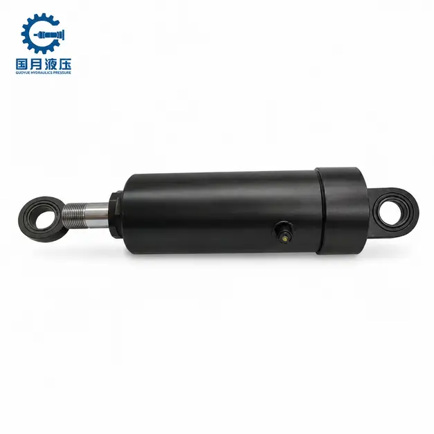
Before inspection, securely support any loads that may move or fall, isolate the power supply according to equipment specifications, and verify that residual pressure is present. A zero reading on the pressure gauge at the pump end does not necessarily mean there is no pressure inside the cylinder; therefore, do not attempt to relieve pressure by loosening fittings.
The Oil Cannot Return to the Reservoir
When the piston rod retracts, the hydraulic fluid in the working chamber must be drained back to the reservoir. If fluid is trapped inside the cylinder, the piston will have difficulty moving even when pushed by a spring or load. Common causes include a release valve that has not opened, a directional control valve that has not engaged the return line, improperly connected quick-connect fittings, and hoses that are kinked, internally damaged, or have restricted flow. Overfilling the reservoir on certain pumps can also impede fluid return.
Even if the passage is not completely blocked, excessive return flow resistance can still impede retraction. This creates back pressure—the pressure that prevents hydraulic fluid from draining out; when the retraction force is insufficient to overcome the back pressure and friction, the piston rod will come to a stop. The fact that the piston rod extends normally does not prove that the return flow path is functioning properly: pump pressure may force fluid into the hydraulic cylinder, but the weaker retraction force may be unable to drain the fluid smoothly.
You should first consult the operating manual to confirm which valve position is the actual return port, then inspect the hose from a safe location to check for pinching, kinking, or damage. If the malfunction occurs immediately after replacing a hose or quick-connect fitting, prioritize checking for proper part compatibility and connection integrity; when adjustments or disassembly are required, you must first relieve pressure according to specifications—never tighten fittings while the system is under pressure.
The Cylinder Has Insufficient Spring, Gravity, or Load Return Force
Single-acting hydraulic cylinders do not necessarily have return springs. Some rely on springs to return, while others rely on the weight of the load, the mechanism’s own weight, or other external forces. If a spring breaks or the return force decreases, or if external forces are insufficient to overcome friction and return flow resistance, the hydraulic cylinder may fail to retract fully. First, confirm which return mechanism the design uses, then determine whether a failure has actually occurred.
For example, a lifting cylinder that relies on the load to push it back may lose its original return force once the load is supported by other means; this does not necessarily indicate damage to the hydraulic cylinder. Similarly, if a mechanism originally designed to return by gravity is reoriented horizontally, gravity cannot directly push it back along the piston rod unless another return mechanism is in place. The installation orientation and mechanical angle must match the retraction method.
When assessing the issue, verify the retraction type in the model specifications and review whether there have been changes to the load, installation orientation, or link positions. If the cylinder consistently stops near the end of the retraction stroke, this may be related to a reduction in retraction force at that position, or it could be due to increased friction or back pressure; do not assume spring failure based solely on this symptom. Do not “assist retraction” by temporarily adding weights, stepping on, or striking the piston rod; spring inspection and replacement should be performed by maintenance personnel familiar with its energy-storage mechanism.
Mechanical Resistance Is Keeping the Rod Extended
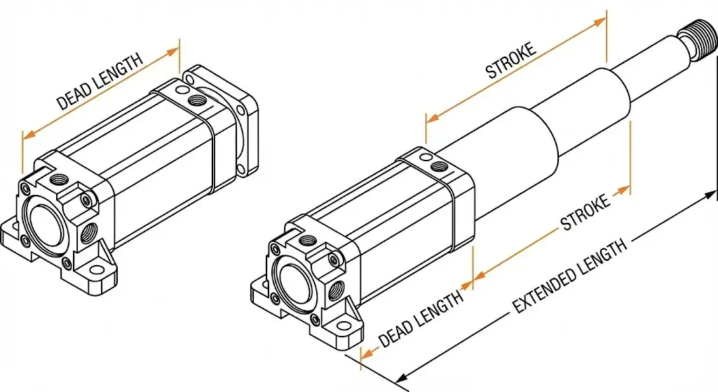
Even if the return oil passage is functioning normally and the return force meets requirements, mechanical resistance may still cause the piston rod to become stuck. The cause may lie within the hydraulic cylinder itself—such as a bent piston rod, damaged guide components, or deformed seals—or in external mechanisms, such as jammed slide rails, misaligned connecting parts, foreign objects blocking the path, or a mechanical locking device that remains engaged. Eccentric loads can also subject the piston rod to lateral forces—that is, forces that push the rod sideways, bend it, or cause it to tilt—increasing friction and potentially damaging the cylinder body.
For example, if a hydraulic cylinder is pushing a push plate that moves along a guide rail, and the guide rail is deformed or the push plate is skewed, the pump pressure may still be able to push it out, but the return spring may not be able to overcome the same resistance to pull it back. In this case, simply replacing the spring may not resolve the issue; it is also necessary to check the load guidance and installation alignment.
A useful troubleshooting record includes: the position where the piston rod stops, whether it stops at the same position every time, and whether there was a previous collision, off-center loading, or maintenance adjustment. If the piston rod consistently gets stuck at the same position, this can serve as a clue to check for local interference or damage, but it is not a definitive diagnosis. After securing the load and isolating the power source, inspect the exposed rod surface, guide rails, and connection points; if it is necessary to disassemble the rod-end connection to distinguish between external mechanical issues and internal cylinder faults, this should be performed by maintenance personnel to prevent sudden movement when disconnecting the assembly.
What Should You Check Before Troubleshooting?
Before beginning troubleshooting, you should first ensure that the load will not move suddenly, that any stored energy in the system is under control, and determine how the hydraulic cylinder normally retracts. Sometimes, the piston rod remains stationary due to a lack of retraction force or because the load-holding device is still functioning properly; this does not necessarily indicate that the hydraulic cylinder is damaged.
Remove or Secure the Load and Relieve Stored Pressure
First, determine whether the hydraulic cylinder is supporting a heavy object, clamping a workpiece, or restraining a spring-loaded mechanism. If the load can be safely lowered according to the equipment’s procedures, lower it to a stable position first; if lowering is not possible, secure it using mechanical supports with sufficient load-bearing capacity or the specified locking devices. Do not disconnect hydraulic hoses, valves, or the hydraulic cylinder while the load is supported solely by the hydraulic system, and do not remove supports directly to check for retraction.
After securing the load, isolate the power supply as per the manual to prevent accidental startup, and release and verify residual pressure using the specified methods. Residual pressure is the pressure that remains trapped in the cylinder chamber, hoses, or valves after shutdown; if the equipment is equipped with an accumulator—a device that stores hydraulic energy—it must also be handled according to specific procedures. Stopping the pump or turning off the power supply does not automatically release all pressure.
Pay particular attention to the location of the pressure gauge. Quick-connect fittings or shut-off valves may isolate the cylinder chamber from the pump side, causing the gauge on the pump side to read zero while the cylinder remains pressurized. Qualified personnel must verify this using the specified pressure measurement points and procedures; do not rely on loosening fittings, pressing the valve spool, or observing for oil drips. Even after hydraulic pressure has been released, springs and pressurized workpieces may still store mechanical energy.
Confirm the Cylinder’s Intended Return Method
Consult the manual using the model number on the nameplate to confirm whether the hydraulic cylinder uses spring return, gravity return, or external load return. “Single-acting” only indicates that the cylinder is hydraulically driven in one direction; it does not necessarily mean it is equipped with a return spring. You must also confirm whether the model extends or retracts under hydraulic pressure to avoid misinterpreting its operating principle.
For example, a lifting cylinder that relies on the load to push it back may lose its original return force after the heavy object is mechanically supported and removed. In this case, the failure to retract on its own does not necessarily indicate that it is jammed. For a mechanism originally designed for gravity return, the return force may also be insufficient if the installation orientation or link angle is changed.
Check the Manual for Locking Valves and Load-Holding Devices
Consult the hydraulic schematics and operating instructions to confirm whether the system is equipped with a hydraulically controlled check valve, a balancing valve, a manual shut-off valve, or a mechanical locking nut. A hydraulically controlled check valve typically requires additional control oil pressure to allow reverse flow; a balancing valve is used to maintain and control load movement; and a mechanical locking nut bears the load through physical contact. Therefore, simply moving the control lever to the “retract” position may not necessarily satisfy all release conditions.
You can first consult the manual to verify the device name, current status, and normal release sequence. If the locking device has not been released according to procedure, the piston rod remaining extended may be a normal load-holding condition rather than a malfunction. For example, a locking nut under load cannot be forcibly unscrewed; the load must first be transferred according to the manufacturer’s procedure before release can occur.
Is the Hydraulic Return Path Blocked?
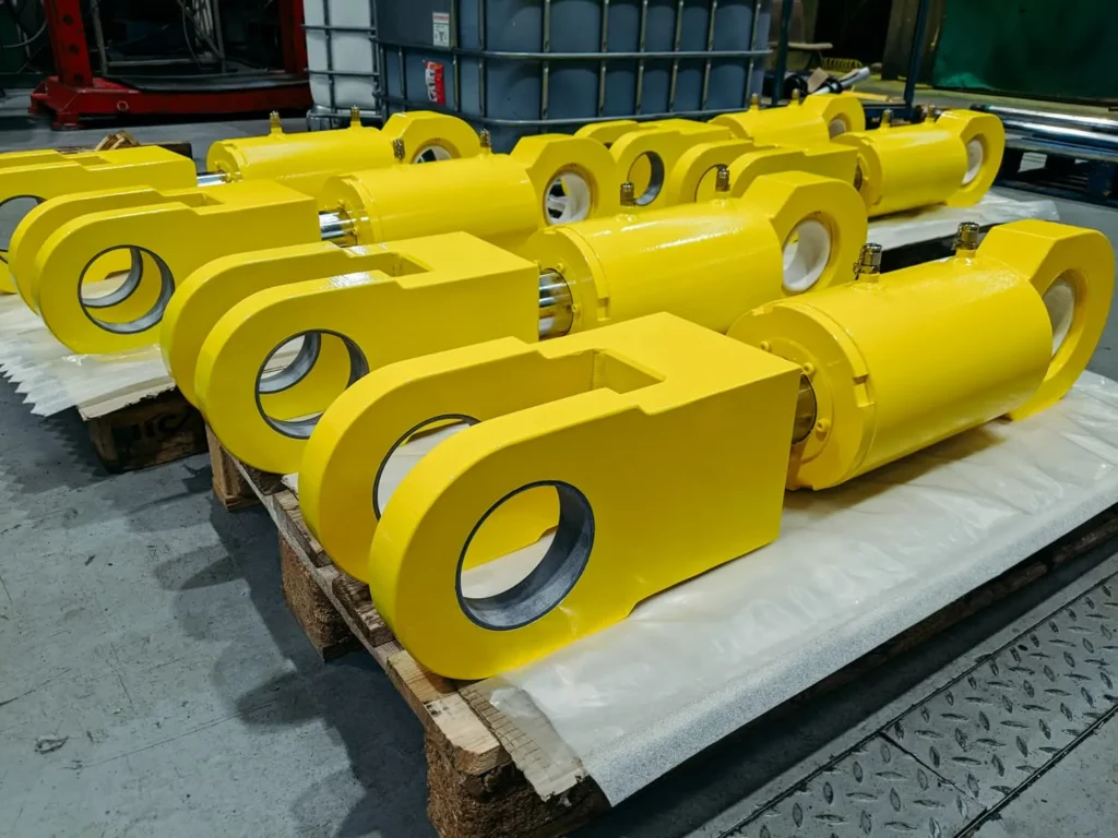
A blocked return flow path is a common cause of a single-acting hydraulic cylinder failing to retract or retracting slowly. For hydraulically extended models, retraction typically requires draining the fluid back to the tank through the original inlet port and hose. If valves, fittings, or piping restrict the return flow, the return force provided by the spring or load may not be sufficient to push the piston back. The fact that the cylinder extends normally does not prove that the return flow path is functioning properly.
You can inspect the actual path from “hydraulic cylinder port—quick-connect fitting—hose—control valve—reservoir”; if the system is equipped with a filter or load-holding valve, these should also be included in the inspection. Before disassembling or installing any components, you must securely support the load, isolate the power source, and verify residual pressure according to the equipment procedures.
Verify the Release or Directional Valve Position
First, consult the manual to confirm which operating position actually allows the hydraulic cylinder to return oil. Manual pumps typically control oil return via a release valve, while other systems may require switching the directional control valve to a specific position. A valve in the neutral position, a stopped pump, or a power-off condition does not necessarily mean that the hydraulic cylinder ports are connected to the reservoir.
The release valve referred to here is an operating valve used for unloading and oil return; do not confuse it with the relief valve that limits the system’s maximum pressure, and under no circumstances should you attempt to resolve retraction issues by adjusting the relief valve setting. You should verify the operating procedure and permissible travel range according to the manual; do not fully unscrew the adjustment screw on your own. A closed release valve is also listed as a cause of retraction abnormalities in the manufacturer’s fault chart.
Fully Engage Quick-Disconnect Couplers
Quick-disconnect couplers typically feature an internal spool valve; fluid can only flow normally once the couplers are properly mated and seated. Incomplete connection, incompatible models, or a damaged spool valve can all restrict fluid return. Sometimes, pump pressure can still force fluid into the cylinder, but once the pump pressure is relieved, the fluid cannot return, resulting in a fault that manifests as “extends but does not retract.”
First, check whether the locking sleeve or threaded sleeve meets the connection requirements specified for that model, and verify the series and specifications of both coupling halves. When reconnecting, ensure that pressure has been relieved on both sides as specified. If the couplings cannot be joined due to pressure, do not force them together with tools, and do not press the valve spool to drain the fluid. A visual fit does not guarantee internal compatibility; pay particular attention to whether the fault occurred after replacing the couplings.
Inspect Hoses for Kinks, Collapse, or Contamination
Check whether the hose is pinched by the frame, guards, or moving parts, and whether there are sharp bends, twists, flattening, or obvious damage. Bends and compression reduce the flow cross-sectional area, increase return flow resistance, and may also damage the hose’s internal structure. Therefore, simply straightening a damaged hose does not mean it has been restored to a usable condition.
Even if the hose appears normal on the outside, internal issues cannot be completely ruled out. Damage to the inner layer, delamination, or foreign objects entering the hose can all restrict flow; hoses that are too long or have an inner diameter that is too small may create significant resistance even without being completely blocked. If the problem occurs after replacing a hose, you should verify the inner diameter, length, fitting orifice size, and fluid compatibility.
Do not squeeze a pressurized hose by hand, and do not disassemble the line to drain oil in order to determine whether it is clear. If you suspect an internal blockage, have a maintenance technician inspect it after depressurizing the system, and follow the manufacturer’s procedures to replace the hose with a qualified one or perform a flow verification test. If contaminants are found, trace their source to prevent re-blockage after simply replacing the hose.
Check the Return Filter, Check Valve, and Tank Path
If the return line passes through a filter, check its clogging indicator or differential pressure indicator. Differential pressure is the pressure difference between the filter’s inlet and outlet, reflecting the resistance encountered by the oil flow as it passes through the filter element. However, an abnormal reading does not necessarily indicate that the filter element is clogged: at low temperatures, the oil becomes more viscous, which can also cause the differential pressure to rise; therefore, the reading should be evaluated in conjunction with the oil temperature and the manufacturer’s instructions.
A check valve allows oil to flow only in the specified direction. If the valve is installed backward, the wrong type is selected, or a hydraulically controlled check valve does not receive the control pressure required to open, the return flow may be blocked. However, a closed load-holding valve may also be in a normal protective state; it should not be immediately assumed to be clogged and removed. You should refer to the schematic diagram to confirm the flow direction, opening conditions, and actual connection location.
At the same time, check whether there is a closed shut-off valve at the tank end, whether the return port is connected incorrectly, or whether the oil level meets requirements. For vented tanks, also check the vent line according to the manual; sealed or pressurized tanks must not be opened without authorization. Do not remove the filter element or bypass the load-holding valve to “try to restore retraction”; instead, address the confirmed malfunction.
Measure Return-Line Backpressure
Backpressure is the pressure on the return line that prevents the hydraulic cylinder from retracting. When measuring, the location is more important than the reading itself: if the blockage is between the hydraulic cylinder and the pump, the pressure gauge on the pump side may have dropped to zero, while the cylinder may still be under pressure. Qualified personnel should check the pressure before and after the cylinder port and related components at the specified measurement points under controlled test conditions, and record the oil temperature and motion status.
The measuring equipment must be capable of withstanding the highest pressure that may occur at the test point while also being able to detect small changes in backpressure. Do not connect a standard low-pressure gauge directly to a common line that may be subjected to high pressure during extension simply because you intend to measure “low backpressure.” To determine whether a valve or filter is causing excessive resistance, compare the pressure differential before and after the component while return flow is present; residual pressure when the system is completely stopped cannot be directly equated with the pressure drop under normal flow conditions.
You can use a simple calculation to understand the effect of back pressure: assuming a hydraulic cylinder has an effective area of 20 cm² and the pressure inside the cylinder relative to the non-working side is 1 bar, it will generate a reverse force of approximately 200 N; the return spring or load must also overcome additional friction from seals and guides. There is no universal value for allowable back pressure applicable to all single-acting hydraulic cylinders; it should be determined based on the specific model and the return force throughout the entire stroke.
Is the Return Force Too Low?
If the return oil path has been confirmed to be unobstructed, but the single-acting hydraulic cylinder still retracts slowly or stops halfway, you need to check whether the return force is sufficient. For hydraulically driven models that extend, the return force provided by the spring, gravity, or an external load must overcome seal friction, mechanical resistance, and return oil back pressure. The problem could be either a reduction in return force or an increase in the resistance that must be overcome; you cannot immediately assume that the spring is damaged.
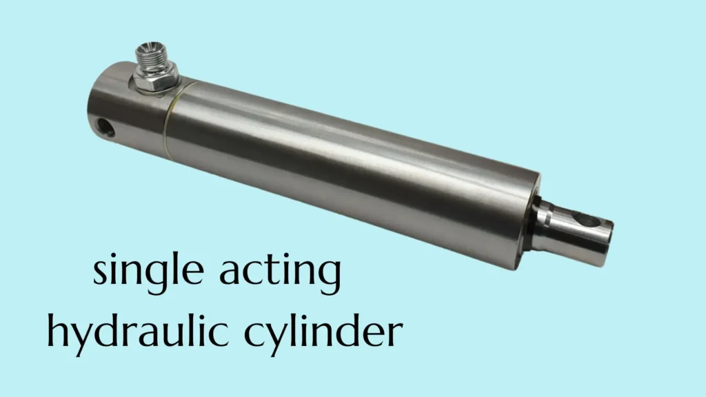
Check for a Broken or Fatigued Return Spring
First, verify based on the model that the hydraulic cylinder indeed uses a spring for return. A broken spring, damage to the connection points, or permanent deformation resulting from long-term use can all reduce the return capability. Fatigue is cumulative damage caused by repeated stress and may eventually lead to breakage; however, slow retraction alone is not sufficient evidence that the spring has failed due to fatigue.
You can record whether the fault occurred suddenly or worsened gradually, as well as whether the stopping position is consistent each time. If the cylinder stops only when approaching the end of its return stroke, this may be related to reduced spring return force at that position, or it could be due to excessive friction or back pressure. You should make a judgment based on the spring characteristics of this model and the inspection results.
Verify Adequate Gravity or Load Assistance
If the hydraulic cylinder uses gravity or load-assisted retraction, you need to confirm that the current load can push the piston rod back in the correct direction. Unlike spring-return models, load-return models may not retract on their own in the absence of an external return force.
For example, a lifting cylinder that normally relies on the weight of a platform to retract may lose its retraction force once the platform is caught by a mechanical support. Similarly, if a mechanism originally installed vertically and relying on gravity for retraction is reconfigured to a horizontal orientation, gravity cannot directly push the piston rod back unless a mechanism such as a connecting rod is used to transmit the retraction force. In these situations, failure to retract is likely due to a change in the retraction conditions rather than an internal failure of the hydraulic cylinder.
Remove Excess Tooling Weight and External Resistance
Whether excess tooling weight hinders retraction depends on the installation orientation. For example, in a press-fit cylinder where the piston rod extends downward, the tooling at the rod end must be lifted upward during retraction; a heavier press head increases the load on the spring. If the piston rod extends upward, the tooling weight may actually assist retraction. Therefore, “reducing weight” cannot be considered a universal solution for all single-acting hydraulic cylinders.
You should review whether the malfunction occurred after replacing the ram, adding fixtures, or adjusting the mounting position, while also checking for binding in the guide rails, pivot points, and connecting components. Eccentric tooling may also generate lateral forces—that is, forces that push the piston rod off-center from the side—increasing friction in the guides and seals. Even if the hydraulic cylinder can still extend using pump pressure, the weaker return force may not be sufficient to overcome these resistances.
Compare the weight, center of gravity, and mounting method of the existing fixture with the original design. To remove attachments and verify their impact, first securely support the fixture, isolate the power source, and confirm the residual pressure; then have maintenance personnel conduct tests in accordance with regulations. Reducing unnecessary weight is not a substitute for correcting misaligned guide rails, skewed connections, or damaged piston rods.
Consider Cold or High-Viscosity Hydraulic Oil
Viscosity can be understood as the “thickness” of a liquid as it flows. When the oil temperature is low or the viscosity is too high, the resistance encountered by hydraulic oil as it flows through hoses, fittings, and valves typically increases, requiring the return force to overcome greater back pressure. Low temperatures may also alter seal friction; therefore, abnormal retraction during cold start-up does not necessarily indicate a decrease in spring force.
If the equipment exhibits noticeably slow retraction during a cold start but improves after being warmed up according to normal procedures, this is an indication of temperature-related resistance; however, this alone is not sufficient to rule out a local blockage. You can record the oil temperature and retraction time under the same load, stroke, and valve position, in accordance with the manufacturer’s permitted test conditions, and then verify whether the actual oil meets the requirements.
Could Air, Oil Level, or Reservoir Venting Be the Cause?
Yes. Trapped air in the system, overfilling the reservoir, and obstructed reservoir venting can all cause the hydraulic cylinder to retract slowly, incompletely, or not at all. For single-acting hydraulic cylinders that rely on springs or gravity for return, you should pay particular attention to these issues, as the return stroke must rely on limited return force to push the hydraulic fluid back into the reservoir. The manufacturer’s troubleshooting documentation also lists these causes.
Bleed Trapped Air From the System
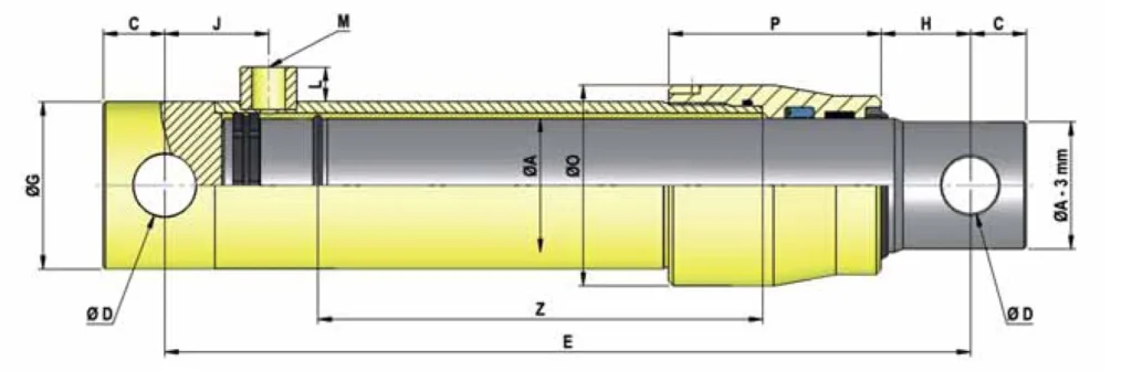
If you have recently replaced hydraulic hoses, topped off the hydraulic fluid, or repaired a hydraulic cylinder, and subsequently experience jerky motion, vibration, or poor retraction, it is worth checking for trapped air—that is, air bubbles that have not been bled out. Air is more compressible than hydraulic fluid and can cause unstable motion. However, these symptoms should only be used as clues for troubleshooting; you cannot determine that an air problem exists based solely on jerking.
You should bleed the system according to the instructions for the specific model. For systems that allow bleeding through reciprocating motion, you can slowly extend and retract the cylinder several times at low pressure—provided the load is safely supported and the work area is clear—to observe whether motion returns to normal. Portable equipment sometimes requires adjusting the positions of the pump and hydraulic cylinder to allow air to return to the reservoir more easily; For permanently installed hydraulic cylinders, follow the specified bleeding procedure; do not simply apply methods used for other equipment.
Do not attempt to “bleed” the system by loosening high-pressure hydraulic hose fittings. Even if the pressure gauge on the pump reads zero, pressure may still remain inside the hydraulic cylinder due to a blocked oil path. If the hydraulic cylinder is completely immobile and unable to perform a normal bleeding cycle, first ensure that any residual pressure is safely released; do not repeatedly pressurize the system in an attempt to force it open.
Correcting an Overfilled Reservoir
For common single-acting cylinders that extend hydraulically and retract via spring or gravity, fluid from the reservoir enters the cylinder during extension, so a drop in fluid level is a normal occurrence. If you top off the reservoir to the full mark while the piston rod is extended, the fluid returning during retraction may exceed the reservoir’s capacity. This may cause fluid to overflow or build up pressure inside the reservoir, obstructing the return flow. Manufacturers explicitly require that fluid levels be checked and topped off with the hydraulic cylinder in the specified position.
Here’s an illustrative example: After the hydraulic cylinder extends, you notice the fluid level has dropped and top it off; subsequently, as the piston rod retracts, the fluid that previously entered the cylinder flows back, causing the reservoir to become overfilled. Therefore, you should check the oil level with the equipment in its specified shutdown position; for the standard single-acting cylinder described above, it is typically necessary to fully retract the cylinder before adjusting the oil level according to the markings. If the cylinder is currently stuck in the extended position, follow the maintenance procedure to drain the excess fluid, restore retraction, and then verify the final oil level—do not top off the oil directly based on the current level.
It is also important to distinguish between excessively high and low oil levels: A low oil level is more commonly manifested by insufficient extension or abnormal oil supply; it does not necessarily mean that oil needs to be added simply because retraction has failed. If you are matching a pump to a reservoir, ensure that the available oil volume meets the hydraulic cylinder’s extension requirements and that the reservoir can accommodate the returning fluid; refer to the equipment manual for specific filling quantities—do not uniformly follow the rule of “filling to 80 percent capacity.”
Clean or Replace a Clogged Breather
A tank breather is a component that allows air to enter and exit the tank while minimizing the entry of external contaminants. In tanks that need to be vented to the atmosphere, when a hydraulic cylinder retracts, the fluid returns and the fluid level rises, requiring the air inside the tank to be expelled. Based on this operating principle, if the breather becomes clogged, pressure inside the tank may rise, creating back pressure that impedes fluid return—that is, the opposing pressure encountered as the fluid flows back. Power Team’s maintenance instructions explicitly list “pressure inside the tank” as a cause of failure to retract and require cleaning the fill/vent cap.
First, verify that the vent is in the operating position specified in the manual, then check whether it is blocked by dust, sludge, or other debris. When disassembly is necessary, first shut down the machine, support the load, and relieve system and reservoir pressure according to specifications; clean washable components as required, and replace filter elements that cannot be cleaned or are already failed. After reassembly, compare the retraction performance under the same load and oil temperature conditions; only if there is a noticeable improvement is there sufficient evidence to conclude that a blocked vent contributed to the failure.
When replacing parts, do not rely solely on whether the threads fit; ensure that the replacement meets the original equipment’s requirements for venting capacity, filtration, and pressure settings. Not all oil tanks should be vented directly to atmosphere: some pumps use non-vented tanks, and some breather caps are designed to maintain a specified internal tank pressure. Do not leave the oil tank cap removed for extended periods as a solution, and do not modify such systems to open venting without authorization.
Is the Cylinder Mechanically Binding?
Possibly. Mechanical sticking refers to a situation where the piston rod, piston, or external linkage cannot move smoothly due to deformation, misalignment, or abnormal friction. For single-acting hydraulic cylinders that rely on springs or gravity for retraction, even if hydraulic pressure can still push the cylinder to extend, the relatively small retraction force may be insufficient to overcome these resistances. Therefore, the fact that the cylinder “can extend” does not necessarily prove that there are no mechanical issues.
If you notice that the hydraulic cylinder consistently stops at a similar position, or if retraction becomes difficult only after repair or reinstallation, you should prioritize inspecting the mechanical components. However, these are merely clues; you must still rule out residual pressure inside the cylinder and obstructed return flow. Before inspection, shut down the machine, isolate the power source, and securely support the load; do not attempt to forcefully clear the sticking by increasing pressure or striking the piston rod.
a. Inspect the Rod for Bending, Scoring, or Side Load
First, inspect the exposed piston rod for obvious bending, longitudinal grooves, dents, or peeling plating. Scoring refers to grooves formed on the surface due to abnormal friction; a side load is a force that pushes the piston rod from the side, deviating from its extension or retraction direction. Lateral loads press the piston rod against one side of the guide components, increasing wear and potentially damaging the rod surface and seals.
After shutting down the machine, clean the visible rod surface, inspect for damage using side lighting, and record the extension length at the time of the failure. If wear is particularly noticeable on one side, or if the cylinder gets stuck at a similar location every time, further inspection for off-center loading, bending, or localized damage should be conducted based on the mechanical motion relationship; however, even if the rod appears straight to the naked eye, slight bending cannot be ruled out. If necessary, have maintenance personnel measure the straightness according to the manufacturer’s specifications; do not apply a generic “allowable bending amount.”
For example, when a hydraulic cylinder drives a platform moving along a guide rail, if the guide rail is skewed, the platform may pull the piston rod to one side. In this case, simply replacing the seals will not eliminate the source of the off-center load. During selection and installation, ensure that a suitable guiding mechanism bears the lateral forces and verify the hydraulic cylinder’s allowable side-load conditions; do not assume that the piston rod can double as a guide rail.
b. Check Mounting Alignment and Pin Freedom
Mounting alignment means ensuring that the extension and retraction direction of the hydraulic cylinder matches the motion requirements of the driven mechanism. You must not only check alignment in the retracted position but also inspect the extended position and the intermediate motion. Mounting bracket offset, bracket deformation, or interference from connecting mechanisms can all cause the hydraulic cylinder to be subjected to lateral compression during part of its stroke. Parker’s installation instructions require checking alignment in both the extended and retracted positions and confirming that swing-type mounts do not experience interference throughout the entire working arc.
For articulated mounts such as ear rings and fork brackets, you should verify that the articulation point formed by the pin and bushing can swing smoothly as designed, rather than requiring each pin itself to rotate freely. Some pins are fixed by design, with rotation occurring at the bushing. Check for corrosion, insufficient lubrication, bushing damage, and whether the mounting bracket is pinching the components that need to rotate.
For example, when a hydraulic cylinder drives a tilting arm, the cylinder body typically needs to change angle along with the mechanism. If the articulation point is seized, the tilting arm will still move along an arc, and the piston rod may be forced to withstand bending forces. Therefore, linear and oscillating motions should be matched with appropriate mounting configurations; when angular changes occur in multiple directions, connection solutions such as spherical bearings and their allowable swing angles must also be evaluated.
To distinguish between a jam in the external mechanism and a jam within the hydraulic cylinder itself, maintenance personnel should, after the load and the cylinder body have been supported separately and the pressure and other stored energy have been safely released, disconnect the connection according to maintenance procedures and inspect it. Do not pull out the pin under load, nor test the cylinder by continuing operation after loosening the mounting bolts. For gravity-return cylinders, disconnecting the load may simultaneously result in the loss of return force; therefore, the fact that the cylinder “does not retract after disassembly” does not, by itself, prove that it is seized internally.
c. Check for Seal Damage or Internal Contamination
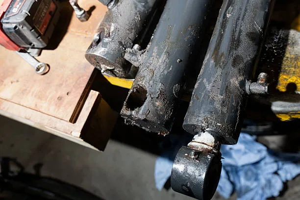
Seal damage does not necessarily cause sticking: normal wear and tear is more likely to result in oil leaks; however, seals that are installed upside down, are the wrong size, or have been nicked during assembly may increase resistance or even prevent movement. If the problem occurs immediately after replacing the seals, you should first verify the part number, installation orientation, and assembly method. Parker’s documentation for single-acting telescopic cylinders explicitly states that incorrect seal orientation can lead to leaks or sticking.
Internal contamination is also worth investigating. Metal particles, sand, dust, and other contaminants entering the hydraulic cylinder can damage the rod surface, cylinder walls, and seals. You can start by checking the dust seal—the component at the rod extension/retraction point that blocks external contaminants from entering—for damage, and have maintenance personnel inspect the filter element and oil sample for abnormal particles; these findings can provide clues but cannot alone pinpoint the exact location of the damage.
If disassembly and inspection are confirmed to be necessary, the seals, guide rings, and mating surfaces should all be inspected simultaneously. Guide rings are used to support and guide moving parts, reducing direct metal-to-metal contact; if they are worn unevenly or damaged, simply replacing the seals may result in the problem recurring quickly. When replacing seals, do not rely solely on dimensions; ensure compatibility with the hydraulic fluid, operating temperature, and original design specifications, and remove any particles or burrs from the seal grooves and surrounding areas.
A Step-by-Step Retraction Diagnostic Sequence
When troubleshooting a single-acting hydraulic cylinder that fails to retract, follow this sequence: “Perform a safety shutdown → Confirm the retraction method → Check the return oil path → Check the reservoir → Determine the retraction force → Bleed air and perform mechanical checks → Retest.” The following primarily applies to hydraulic cylinders that extend hydraulically and retract via spring or gravity; if your equipment relies on active hydraulic retraction, you must also check the oil supply on the retraction side and cannot follow this procedure exactly.
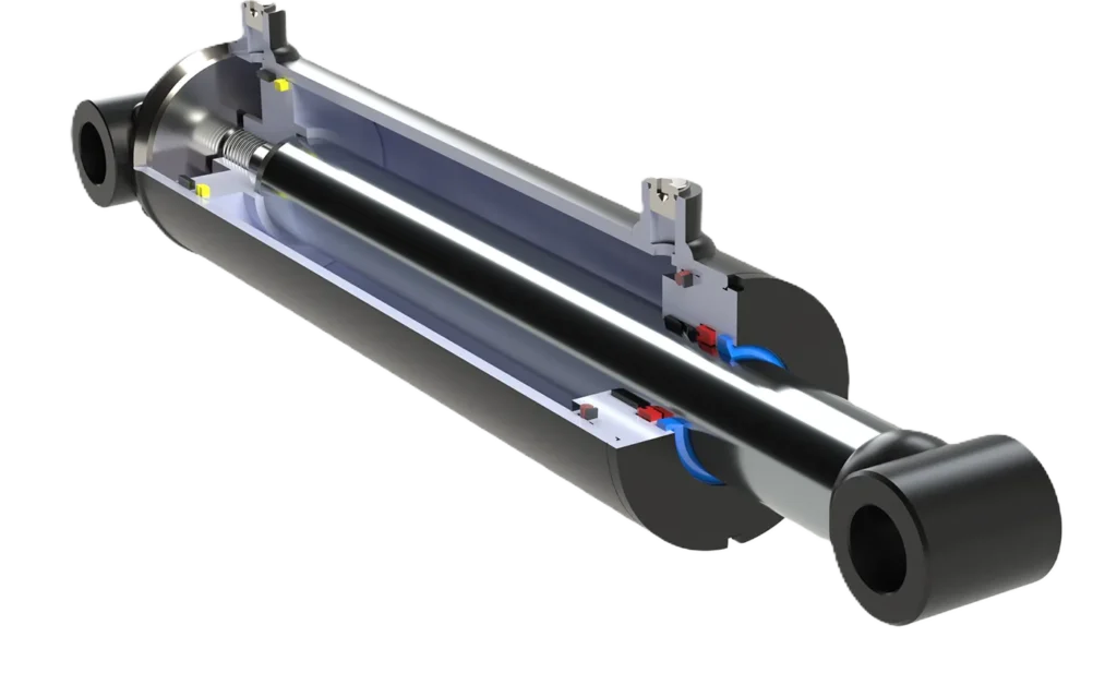
Step 1: Secure the Load Before Inspection
First, shut down the machine, isolate the power source, and secure the load using the mechanical supports specified by the equipment manufacturer to prevent sudden drops during troubleshooting. Before removing hydraulic hoses, pins, or the cylinder body, you must also address residual pressure and stored energy (such as from springs) in accordance with maintenance procedures. A zero reading on the pump-side pressure gauge does not necessarily mean there is no pressure inside the hydraulic cylinder, as pressure may be trapped inside the cylinder by fittings or valves. Do not loosen fittings to “check for hydraulic pressure.”
If obvious piston rod bending, bracket cracking, or hydraulic hose damage is detected, stop the functional test and arrange for repairs immediately. Subsequent inspections requiring power or load movement must be conducted under specified, controlled test conditions; do not attempt to test the system while disassembling it.
Step 2: Confirm the Return Method and Record the Symptom
Check the nameplate, model manual, or hydraulic schematic to confirm whether the hydraulic cylinder retracts via a spring, gravity, or an external mechanism. A load-return cylinder will not retract without an appropriate return load; this may simply indicate a lack of operating conditions and does not necessarily indicate a malfunction. For example, after removing the mechanism originally responsible for retracting the piston rod, you can no longer use “whether it automatically retracts under no-load conditions” to determine if it is functioning normally.
Next, record whether the cylinder remains completely stationary, retracts slowly throughout the entire stroke, or stops at a certain point, and note the extended length, oil temperature, and load status at the point of stoppage. Also, confirm whether the fault occurred after changing the oil lines, replacing seals, or reinstalling the cylinder. This information will help you prioritize inspection of recently modified components, avoiding a situation where adjustments to multiple areas simultaneously make it impossible to pinpoint the cause.
Step 3: Check the Retraction Command and Return Path
Verify that the operating handle or control signal has triggered the retraction state specified by the equipment. For common manual pump systems, open the relief return valve as per the manual; for valve-controlled systems, confirm that the control valve has actually established a return path. The fact that the motor has stopped or the button has been released does not necessarily mean that the fluid inside the cylinder can return to the tank.
Next, check whether the hoses are kinked or pinched, whether the quick-connect couplings are properly paired and fully connected, and whether the return valve is in the correct position. Inadequate coupling connections, obstructed return flow, and hoses with too small an inner diameter can all cause abnormal retraction. When adjusting or replacing couplings, you must first safely relieve pressure; do not use a load-holding bypass device to troubleshoot the fault.
Step 4: Verify Reservoir Oil Level and Venting
Check that the oil level meets the requirements specified in the manual, and verify the operating position of the venting device. For standard hydraulic single-acting extension cylinders, the final oil level should typically be verified after the cylinder has fully retracted; if you refill the reservoir while the piston rod is extended, the returning oil may cause the reservoir to become overfilled. If the cylinder cannot retract at this time, do not blindly top off the oil based on a low oil level; instead, follow the maintenance procedure, then recheck once retraction has been restored.
For tanks that require venting, check whether the breather is clogged or still in the shipping-closed position. The breather is a component that allows air to enter and exit the tank; if venting is obstructed, internal pressure may impede oil return. However, some pumps use non-vented reservoirs, so “loosening the reservoir cap” should not be considered a universal test method.
Step 5: Distinguish Between Return Resistance and Insufficient Return Force
If the previous checks fail to identify the cause, have a technician check the pressures on the cylinder side and the return side through the designated pressure ports. **Back pressure is the pressure that must be overcome for fluid to return, but a pressure reading alone does not prove a blockage in the hydraulic circuit. ** The load itself may also generate pressure within the cylinder; therefore, a judgment must be made based on the circuit, the load, and the location of the measurement point. It cannot be expected that all systems will display zero pressure during retraction.
The key to this assessment is whether the return force can simultaneously overcome both hydraulic resistance and mechanical friction. If measurements confirm abnormal return resistance, continue to locate the restricted component; if the return path is normal, check the condition and installation orientation of the spring, as well as whether the external return force is sufficient. Based on this force relationship, for spring- or gravity-return cylinders lacking return force, simply increasing pump pressure will not resolve the issue.
Step 6: Check for Trapped Air and Mechanical Binding
If the problem occurs after disassembling and reassembling the hydraulic lines and is accompanied by jerking or intermittent motion, follow the bleeding procedure for that specific model. Perform low-pressure, slow reciprocating bleeding only when the equipment permits and can move safely; if the cylinder is completely stuck, do not repeatedly apply pressure to force it through its stroke. The manufacturer’s bleeding guidelines emphasize avoiding pressure buildup and using the restoration of smooth motion as the basis for assessment.
If bleeding does not improve, or if the cylinder consistently stops at a similar position, inspect the rod surface for damage, verify proper alignment during installation, and ensure the articulation points move freely. If the malfunction occurs immediately after replacing seals, prioritize verifying the seal part number, orientation, and installation. When it is necessary to disconnect external mechanisms or disassemble the cylinder, have a maintenance technician handle the task; in particular, keep in mind that disconnecting the load from a gravity-return cylinder may simultaneously eliminate its return force.
Step 7: Retest Under Comparable Conditions
After correcting each identified issue, reassemble the unit according to specifications and retest under similar starting positions, loads, and oil temperatures, recording the retraction time and final stopping position. First, perform low-risk functional checks permitted by the manual, then verify under actual operating conditions; do not assume the fault has been resolved simply because the cylinder moved once under no-load conditions.
If retraction requires additional force or can only be completed partially, continue investigating the cause. If test results indicate that insufficient return force is due to an inherent design issue, you should re-evaluate the return force, friction, and allowable back pressure across the entire stroke, rather than simply replacing the spring with a stronger one or increasing the load. This will also help you determine whether the current single-acting return solution is truly suitable for the equipment.
When Should You Repair or Replace the Cylinder?
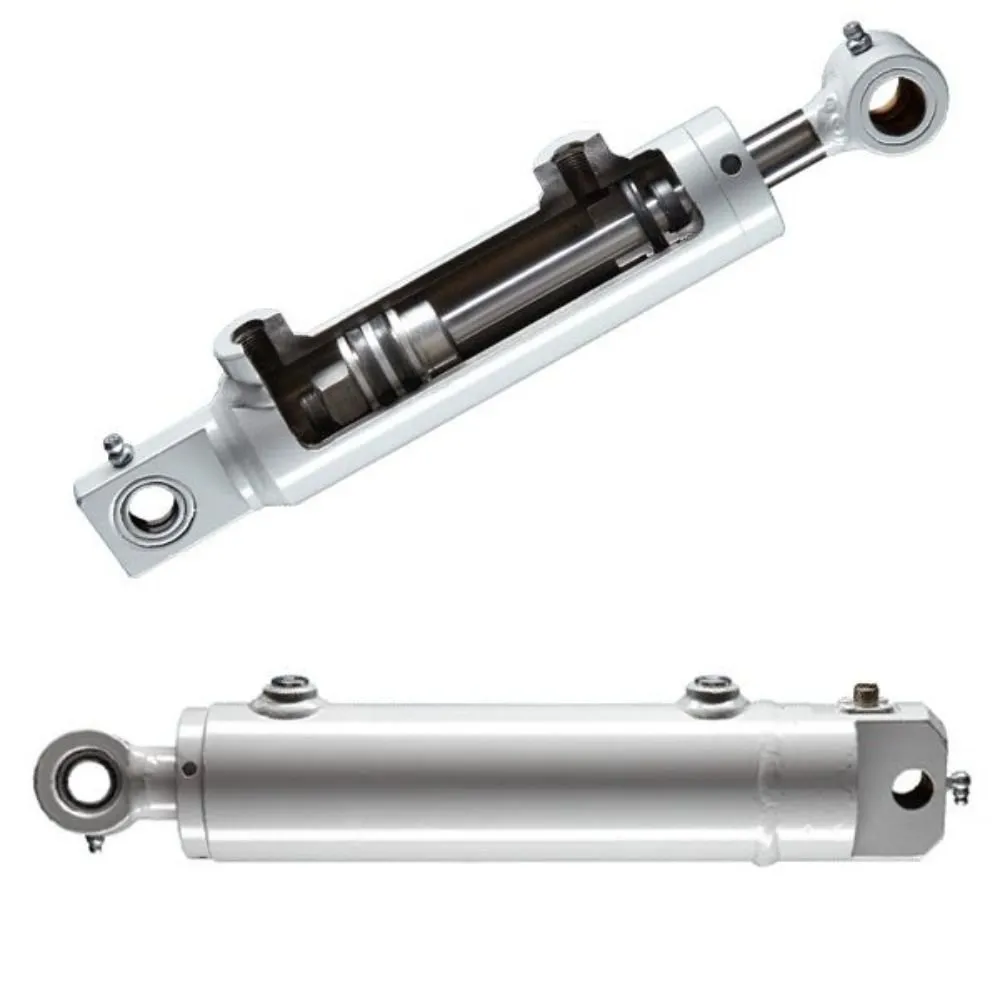
If the damage is limited to replaceable springs, seals, or piston rods, and the main structure still meets the manufacturer’s requirements, repair should be considered as the first option; if the pressure-bearing structure is severely damaged and cannot be restored to specifications, or if safety performance cannot be verified after repair, replacement of the entire cylinder should be considered. You need to compare not only the cost of parts, but also the costs of disassembly, inspection, downtime, and the risk of recurrence. Manufacturers will also determine whether repair is worthwhile based on the extent of the damage and the economic feasibility of the repair.
Broken Spring or Damaged Rod
For single-acting hydraulic cylinders with spring-return mechanisms, once a broken return spring is confirmed, use should be discontinued and repairs arranged. If a matching spring is available for that model, and the mounting points and other components show no associated damage, it is usually possible to evaluate replacing just the spring rather than immediately scrapping the entire cylinder. However, springs should not be selected based solely on external dimensions; they must also meet the original design requirements for return force and working stroke. Do not substitute with a “stronger spring” found at hand.
In the case of a damaged piston rod, distinguish between surface issues and structural issues. Scratches or peeling plating may compromise the seals; obvious bending, cracks, or damage to connection points require further evaluation of load-bearing capacity. You should have maintenance personnel inspect the rod’s straightness, surface condition, and whether the guide components are also damaged before deciding whether to replace the rod assembly or the entire cylinder. Parker’s maintenance documentation requires that mechanical fractures or permanent deformation be evaluated by the engineering department rather than repaired directly on-site.
For example, if a piston rod is bent due to misalignment during installation, simply replacing it with a new rod may result in repeated damage. Therefore, installation and loading issues must be corrected before repair. Do not assume that the rod’s ability to extend and retract after being tapped straight, heat-straightened, or welded constitutes proof that its rated load-bearing capacity has been restored.
Recurring Seal Failure or Barrel Damage
When seals fail repeatedly, you should first identify the cause rather than simply continuing to replace them. You need to check the rod surface and cylinder bore for grooves, verify whether the guide components are unevenly worn, ensure proper alignment during installation, and confirm that the seal material is suitable for the hydraulic fluid and operating temperature. Otherwise, even if the new seals are the correct size, they may fail again quickly. Parker’s troubleshooting guidelines list improper installation, damage to mating surfaces, and material incompatibility as factors that require inspection.
If the main components are found to be within acceptable limits after inspection and the cause of the failure has been eliminated, replacing the appropriate seals and worn parts is usually a viable repair option. However, if the cylinder barrel—the cylinder that houses the piston and withstands internal oil pressure—exhibits cracks, bulging, obvious deformation, or severe internal wall damage, it should be taken out of service immediately. The manufacturer or a professional repair facility should then determine whether the cylinder barrel assembly can be replaced; if the specified structure and dimensions cannot be restored, the entire cylinder must be replaced.
Do not assume that cylinder wall scratches can always be resolved by honing. Any repair involving material removal will alter the fit dimensions; whether this is permissible must be determined based on the specific model’s repair requirements. For example, Parker explicitly requires the replacement of damaged cylinder bodies for certain series; conversely, some Enerpac models do not offer cylinder body repair parts and require replacement of the entire hydraulic cylinder. These regulations cannot be applied interchangeably.
A practical approach is to request a repair quote that specifies the location of the damage, the parts requiring replacement, the cause of failure, and the post-repair verification items, and then compare this with the option of purchasing a new cylinder. If replacement is decided upon, in addition to the bore diameter and stroke, verify the rated pressure, return mechanism, retracted length, mounting interfaces, and fluid ports; do not assume that a replacement is suitable simply because the “dimensions are roughly the same.”
Unsafe Field Repair Conditions
The absence of safe repair conditions on-site means that on-site disassembly and repair should be halted; it does not necessarily mean that the hydraulic cylinder must be scrapped. If you cannot reliably support the load, confirm that residual pressure has been released, or lack specialized tools to control spring energy storage, you should arrange for a professional to handle the situation. Even when power is disconnected, a spring-loaded hydraulic cylinder may still release mechanical energy during disassembly, causing parts to suddenly eject.
Similarly, do not begin disassembling fittings simply because the pressure gauge on the pump side reads zero. Fittings or valves may trap pressure inside the cylinder; repair incidents documented by Enerpac demonstrate that a zero-pressure reading on the pump side does not prove that the hydraulic cylinder has been safely depressurized.
Even if the cylinder can be safely disassembled on-site, it is generally more appropriate to send it in for repair if proper cleaning and assembly conditions, the correct replacement parts, measuring tools, or post-repair testing facilities are not available. Before returning the cylinder to service, leak tests, operational tests, and the specified pressure tests must be completed in accordance with the maintenance requirements for that model. “It moves when reassembled” merely indicates that movement has occurred; it does not prove that the repair meets acceptance criteria.
Frequently Asked Questions About Single Acting Cylinder Retraction
Can a Loose Coupler Prevent a Cylinder From Retracting?
Yes. For quick-connect couplers with internal self-sealing valves, an improper connection may prevent the valve spool from opening fully, obstructing the return of hydraulic fluid from the cylinder to the reservoir. Therefore, even if the coupler does not leak, this does not guarantee that the fluid path is unobstructed; the manufacturer’s troubleshooting documentation explicitly lists an improper coupler connection as a cause of retraction abnormalities.
You should first shut down the machine, securely support the load, and relieve pressure according to specifications before checking whether the couplings match and whether the locking mechanism is fully engaged. Do not tighten or disconnect the couplings while under pressure, as trapped pressure may still exist inside the cylinder even when the pressure gauge on the pump side reads zero.
Why Does the Cylinder Retract Only When the Pump Is Off?
This may be a normal design feature, or it may indicate that residual pressure during pump operation is preventing retraction. In some “hydraulic lift, gravity descent” systems, the pump supplies oil during the lift phase; during descent, the pump stops and the descent valve opens, allowing the load to push the oil back into the tank. This type of return mechanism does not require the pump to provide retraction power.
However, if the equipment was originally designed to allow retraction while the pump is running but now requires the pump to be stopped, based on circuit principles, you should check whether the control valve is switching correctly and whether the return flow path is affected by the pump’s flow rate. First, consult the manual to verify whether the retraction command specifically requires the pump to be stopped. Stopping the pump does not automatically open the return flow path; if the load descends on its own after the pump is stopped without a lowering command being issued, you should stop using the equipment and inspect the load-holding function.
Why Does the Cylinder Retract Slowly When the Oil Is Cold?
This is primarily because low temperatures increase the viscosity of hydraulic fluid, making it harder for the fluid to flow. Resistance increases as the fluid passes through hoses, fittings, and valves, and since the spring force or gravity acting on a single-acting cylinder is limited, retraction may slow down. Enerpac’s manual also notes that under extremely cold conditions, the fluid thickens and requires proper preheating to flow smoothly.
You can follow the equipment’s permitted preheating procedure and then compare the retraction times under the same load and starting position. If there is a noticeable improvement after warming up, it indicates that oil temperature and viscosity are likely contributing factors to the problem; if retraction remains slow, the issue cannot be attributed solely to low temperatures. When selecting hydraulic fluid, ensure it meets viscosity requirements for both the minimum startup temperature and normal operating temperature. Do not arbitrarily switch to a thinner fluid just to achieve faster retraction in winter, and do not use an open flame to heat the fluid.
Can You Manually Retract a Load-Return Cylinder?
Some models allow it, but only if the manufacturer permits this operation; do not assume that “load return” means the cylinder can always be pushed back by hand. Load-return cylinders require external force to overcome friction and return flow resistance; some models require considerable return force, so the inability to push it back by hand does not necessarily indicate cylinder failure.
If the manual permits manual assistance for retraction, you must still ensure there is no suspended load, that the return flow path is open as specified, and that you use the designated method of applying force while avoiding areas where you could get pinched. Do not stand on the piston rod, strike it, or force it back with a pry bar; even after disconnecting the hydraulic hoses, the self-sealing fittings may still retain fluid. If your normal operating conditions frequently lack sufficient return load, you should reevaluate spring-return or double-acting solutions rather than relying on manual assistance over the long term.
Work with a IATF 16949 Certified Blind Rivet Manufacturer
Get High Quality Rivets Instead of Huck and Avdel Rivets
Explore Rivmate Cases

Hey There, I'm Melody!
We are a hydraulic cylinder manufacturer. For over 20 years, we have focused on producing reliable hydraulic cylinders. Need a hydraulic cylinder solution? Feel free to contact us.