Home / What Is a Double Acting Hydraulic Cylinder
What Is a Double-Acting Hydraulic Cylinder?
- Author: GY Hydraulic
- 20+ Years of Manufacturing
Double-acting hydraulic cylinders utilize pressurized hydraulic fluid on both sides of the piston to generate controllable force during both extension and retraction. Compared to single-acting hydraulic cylinders, this bidirectional operation allows for better control of motion, speed, and force; therefore, double-acting hydraulic cylinders are widely used in industrial machinery, construction equipment, agricultural systems, material handling, and other hydraulic applications.
In this guide, the GY Hydraulic engineering team will provide a detailed explanation of the working principles, main components, common types, and typical applications of double-acting hydraulic cylinders, as well as the key factors to consider when selecting a cylinder for a specific hydraulic system.
Engineering Note: This article was written by the GY Hydraulic engineering team and reviewed by technical personnel with extensive experience in hydraulic cylinder design, application, and quality control. Any calculation results provided in this article are for preliminary selection reference only. Final hydraulic cylinder specifications should be verified based on actual loads, installation methods, hydraulic circuits, operating pressure, operating cycles, and operating environments.
Table of Contents
What Is a Double Acting Hydraulic Cylinder? Full Guide
A double-acting hydraulic cylinder is a type of hydraulic actuator that controls extension and retraction by alternately applying pressurized fluid to both sides of the piston. When pressure is applied to the top end, the piston rod extends; when pressure is applied to the rod end, the piston rod retracts. Therefore, the two ports of the hydraulic cylinder are not fixed as permanent inlet and return ports—their functions switch depending on the direction of movement.
In a typical single-rod double-acting hydraulic cylinder, the area of the piston at the top end is greater than the effective annular area at the rod end. Consequently, under comparable pressure conditions, the cylinder typically generates greater thrust during extension; conversely, at the same fluid flow rate, the retraction speed is generally faster. This makes double-acting cylinders well-suited for applications requiring controlled reciprocating motion, bidirectional thrust, or repeatable speed control, such as construction machinery, agricultural equipment, material handling systems, and industrial automation.
Selection Guidelines
When selecting a cylinder, it is essential to not only consider the bore diameter and stroke but also to comprehensively evaluate factors such as the required extension force, retraction force, operating speed, mounting method, available installation space, load direction, and the hydraulic circuit.
Theoretical thrust calculations should be based on the actual available pressure at the cylinder ports, rather than simply using the pump’s maximum pressure or the cylinder’s rated pressure. In actual operation, back pressure in the return line, friction from seals, pressure losses in valves and hoses, as well as dynamic or varying loads, can all reduce the cylinder’s available thrust.
If the application requires only unidirectional powered motion and the return stroke can be reliably accomplished by gravity, a spring, or an external load, a single-acting cylinder may provide a simpler, lower-cost solution.
Core Components and the Two Pressure Ports
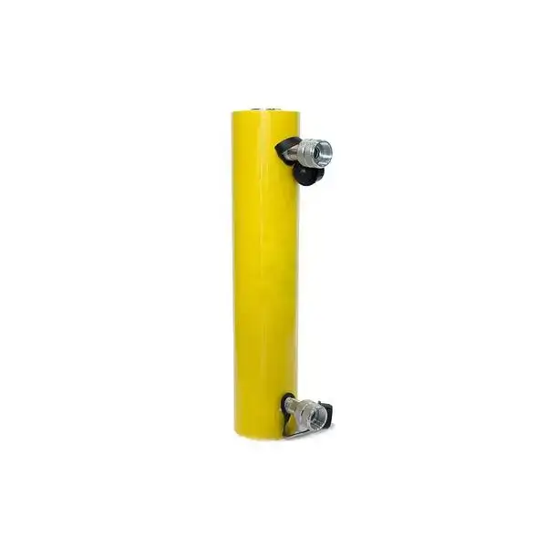
The core of a double-acting hydraulic cylinder can be summarized as two parts: a mechanical structure that performs linear motion, and two hydraulic ports connected to the working chambers on either side of the piston. These two ports allow hydraulic fluid to alternately enter both sides of the piston, thereby enabling the piston rod to actively extend and retract. These two ports control the pressure on either side of the piston, respectively.
① What are the main components of a double-acting hydraulic cylinder?
Double-acting hydraulic cylinders typically consist of a cylinder barrel, piston, piston rod, cylinder head and end caps, guide components, seals, and hydraulic ports. While hydraulic cylinders of different designs and applications may vary in detail, the following components directly affect the cylinder’s load-carrying capacity, motion stability, sealing performance, and service life.
- Cylinder Barrel
The cylinder barrel is the main structural component of a hydraulic cylinder and serves as the working chamber for the piston’s reciprocating motion. The dimensional accuracy, roundness, and surface quality of the cylinder barrel’s bore affect piston sealing, friction, and operational stability. - Piston
The piston divides the interior of the cylinder barrel into two working chambers: the non-rod chamber and the rod chamber. Hydraulic fluid acts on the effective area of the piston, converting hydraulic pressure into linear thrust or tensile force.
Piston Rod
The piston rod connects the internal piston to the external load, transmitting the linear motion and force generated by the hydraulic cylinder to the equipment. The diameter of the piston rod not only affects mechanical strength and stability but also alters the effective pressure-bearing area on the retraction side, thereby influencing the retraction force and movement speed. - Cylinder Head and End Cap
The cylinder head and end cap seal both ends of the cylinder barrel. The rod-side structure typically also provides piston rod guidance, seal mounting, and partial radial support. - Rod Gland / Guide Bush
The rod gland supports and guides the piston rod, ensuring it moves as closely as possible along the hydraulic cylinder’s axis; it also typically serves as the mounting location for the rod seal and dust seal. Inappropriate guide clearance or load conditions may accelerate wear on the piston rod and seals. - Wear Rings / Bearing Rings
Wear rings primarily bear the radial guiding loads of the piston or piston rod, reducing direct contact between the piston, cylinder barrel, and metal guide components. In operating conditions involving lateral loads, the material, dimensions, and arrangement of the wear rings directly affect guiding stability and service life. - Seals
Hydraulic cylinders typically incorporate multiple types of seals rather than a single sealing structure.
Piston seals are used to limit internal leakage between the two working chambers;
rod seals are used to prevent hydraulic fluid from leaking outward along the piston rod;
static seals are used at end caps, cylinder heads, cylinder barrels, and other fixed connection points to prevent leakage at static mating surfaces. - Rod Wiper
The rod wiper is installed at the piston rod exit to minimize the entry of dust, moisture, silt, and other particulate contaminants into the hydraulic cylinder when the piston rod retracts. For construction machinery, agricultural machinery, and outdoor equipment, this component is particularly important for the service life of seals and internal cylinder components. - Hydraulic Ports
Double-acting hydraulic cylinders typically have two ports connected to the working chamber, through which hydraulic fluid enters and exits the cylinder. These two ports are not permanently designated as “inlet” and “return”; their functions switch depending on the direction of the cylinder’s movement. - Cushion Components (Optional)
Some double-acting hydraulic cylinders are equipped with cushioning mechanisms at the end of their stroke. By limiting the flow rate of hydraulic fluid during the final stage of the stroke, these mechanisms cause the piston to gradually decelerate as it approaches the end of its travel, thereby reducing mechanical shock, noise, and the instantaneous loads on connected components. Not all double-acting hydraulic cylinders are equipped with cushioning devices; their inclusion should be determined based on movement speed, load, and equipment requirements.
② What do the two hydraulic ports do?
Double-acting hydraulic cylinders typically have two working ports: one connected to the rodless chamber and the other to the rod chamber. Both ports are involved in both the inlet and return of fluid, and their functions switch as the direction of the cylinder’s movement changes; therefore, it is not appropriate to simply designate one as the “inlet port” and the other as the “return port.”
When the hydraulic cylinder extends, pressurized fluid typically enters the rodless chamber, pushing the piston and piston rod outward; at the same time, the hydraulic fluid in the rod chamber is discharged through the other port and returns to the hydraulic circuit.
When the hydraulic cylinder retracts, the directional control valve reverses the flow of fluid, allowing pressurized fluid to enter the rod chamber and push the piston in the opposite direction, causing the piston rod to retract; at this point, the hydraulic fluid in the rodless chamber is discharged through the corresponding port.
Therefore, it can be simply understood as follows:
During extension: The non-rod chamber port typically receives pressure oil, while the rod chamber port returns oil;
During retraction: The rod chamber port typically receives pressure oil, while the non-rod chamber port returns oil.
The core function of these two ports is to enable the hydraulic system to independently control the pressure and flow rate on either side of the piston, thereby achieving active extension and retraction of the hydraulic cylinder. By controlling the flow of fluid entering and exiting the two working chambers, the direction and speed of the hydraulic cylinder’s movement can be further regulated; if the system is equipped with a proportional valve, servo valve, or position feedback device, even more precise speed and position control can be achieved.
Port Sizes Should Not Be Selected Based Solely on Installation Space
When selecting the port specifications for a hydraulic cylinder, one should not consider only whether the thread size facilitates installation or whether there is sufficient space on-site for fittings. The ports must also be matched to the flow requirements of the entire hydraulic circuit, including:
- the peak flow rate during hydraulic cylinder operation;
- the inner diameter of the oil lines or hoses;
- the flow capacity of directional control valves or proportional valves;
- the allowable pressure drop generated by the ports, fittings, and piping;
- the length of the piping, the number of bends, and the actual layout;
- the effect of hydraulic fluid temperature and viscosity on flow resistance.
If the port, valve, or piping dimensions are too small, excessive local flow resistance may cause high pressure drops even if the hydraulic pump can provide sufficient flow. Actual symptoms may include reduced hydraulic cylinder speed, increased system back pressure, rising oil temperature, and a decrease in the hydraulic cylinder’s actual available output force.
Therefore, port specifications should be determined as part of the joint design of the hydraulic cylinder and the entire hydraulic circuit, rather than selected solely based on thread size or ease of installation.
③ Why do the force and speed differ in the two directions?
For a typical single-rod double-acting hydraulic cylinder, the output force and movement speed differ between extension and retraction. The fundamental reason is that the piston rod occupies part of the area on the rod side, so the effective pressure-bearing areas on the two sides of the piston are different.
Let:
– D: cylinder bore diameter
– d: piston rod diameter
– A_p: full piston area
– A_annulus: effective area on the rod side, also called the annular area
The full piston area is:
A_p = πD² / 4
The effective annular area on the rod side is:
A_annulus = π(D² – d²) / 4
Since:
A_annulus < A_p
The cylinder therefore behaves differently in the two directions when other conditions remain the same.
Extension:
Pressurized fluid acts on the full piston area A_p in the non-rod chamber. Because the effective pressure-bearing area is larger, the cylinder can usually generate greater extension force at the same effective pressure. However, at the same inlet flow rate, a larger chamber volume must be filled, so the extension speed is usually slower.
Retraction:
Pressurized fluid acts on the annular area A_annulus in the rod chamber. Because the piston rod occupies part of the effective area, the retraction force is usually lower than the extension force at the same effective pressure. However, at the same inlet flow rate, the effective volume to be filled is smaller, so the piston rod usually retracts faster.
For preliminary calculations that ignore backpressure, friction, leakage, and dynamic effects:
F_extend ≈ P × A_p
F_retract ≈ P × A_annulus
The corresponding speeds can be approximated as:
v_extend = Q / A_p
v_retract = Q / A_annulus
Where:
– P is the effective pressure acting on the corresponding working chamber
– Q is the flow rate entering that chamber
In simple terms:
– Larger area → greater force at the same pressure
– Smaller area → higher speed at the same inlet flow rate
Note that the relationships above mainly apply to common single-rod double-acting hydraulic cylinders. In a double-rod or other symmetrical cylinder design, the effective areas on both sides may be equal, so the extension and retraction characteristics can be different.
What should you focus on when selecting a cylinder?
In addition to bore diameter and stroke, you should at least verify the piston rod diameter, the specifications and locations of the two ports, the system operating pressure, the required flow rate, and the available space for piping connections. Larger ports are not necessarily better.
Port sizes should be matched to the system flow rate, pipe diameter, and valves. Therefore, when understanding double-acting hydraulic cylinders, the two ports are more important to understand than the housing structure.
How Does a Double-Acting Hydraulic Cylinder Work?
A double-acting hydraulic cylinder extends and retracts the piston rod by alternately supplying pressurized oil to both sides of the piston. When pressurized oil enters one side, it pushes the piston forward, while the hydraulic oil on the other side is expelled; by switching the direction of the oil flow via a directional control valve, the hydraulic cylinder can be controlled to perform both pushing and pulling motions.
Simply put, both extension and retraction are powered by hydraulic force.
Extension Stroke: Pressure, Force, and Oil Flow
During extension, the directional control valve sends pressurized fluid into the cap-end chamber, pushing the piston and rod outward while fluid from the rod-end chamber returns through the hydraulic circuit. The basic theoretical extension force is:
Theoretical Extension Force = Pressure × Piston Area
For a more realistic estimate, return-side backpressure and mechanical friction should also be considered:
F_extension ≈ P_cap × A_p − P_rod × A_annulus − F_friction
Where:
P_cap = actual pressure in the cap-end chamber
A_p = full piston area
P_rod = return-side pressure in the rod-end chamber
A_annulus = effective annular area on the rod side
F_friction = friction from seals, guides, and other moving components
Return backpressure can increase when hoses or return lines are undersized, valve passages restrict flow, or load-control valves create additional resistance. Therefore, actual extension force is usually lower than the simple theoretical value. The calculated force should be used for preliminary sizing only and should not be treated as a guaranteed continuous output under all operating conditions.
Retraction Stroke: Rod-Side Pressure and Return Flow
During retraction, the directional control valve directs pressurized fluid into the rod-side chamber, pushing the piston back while fluid from the cap-end chamber returns through the hydraulic circuit. Because the piston rod occupies part of the effective pressure area, retraction force is generally lower than extension force at the same pressure.
Theoretical Retraction Force = Pressure × (Piston Area − Rod Area)
A more realistic estimate is:
F_retraction ≈ P_rod × A_annulus − P_cap × A_p − F_friction
Where:
P_rod = actual pressure in the rod-side chamber
A_annulus = effective annular area on the rod side
P_cap = return-side pressure in the cap-end chamber
A_p = full piston area
F_friction = friction from seals, guides, and other moving components
Retraction speed can be estimated by:
v = Q / A
Because the rod-side effective area is smaller, retraction is typically faster than extension at the same inlet flow. However, actual speed depends not only on pump flow but also on valve flow capacity, internal leakage, oil temperature and viscosity, load conditions, and the hydraulic circuit control method. If the return stroke must pull a load, the available retraction force should be checked separately rather than assumed from the extension rating.
Why Are Extension and Retraction Forces Different?
For a typical single-rod double-acting cylinder, the difference in effective piston area explains why extension force is usually higher and retraction speed is usually faster under comparable pressure and flow conditions. However, this rule should not be applied universally. In a double-rod cylinder, the theoretical working areas are equal only when the rod diameters on both sides are the same and the pressure conditions are comparable. Even with equal areas, actual force and speed can still differ because of friction, backpressure, external loads, valve restrictions, and piping differences. Differential or regenerative hydraulic circuits can also change cylinder speed and available force, so calculations based on a conventional circuit may no longer apply directly.
Calculation Example — Not GY Test Data:
Assume a cylinder bore of 80 mm, a rod diameter of 45 mm, and an actuator-side pressure of 16 MPa. Ignoring backpressure, friction, and internal leakage, the theoretical extension force is approximately 80.4 kN, while the theoretical retraction force is approximately 55.0 kN. This example is provided only to illustrate the calculation method and does not represent the rated performance or test results of any GY Hydraulic product.
What Are the Main Double-Acting Hydraulic Cylinder Types?
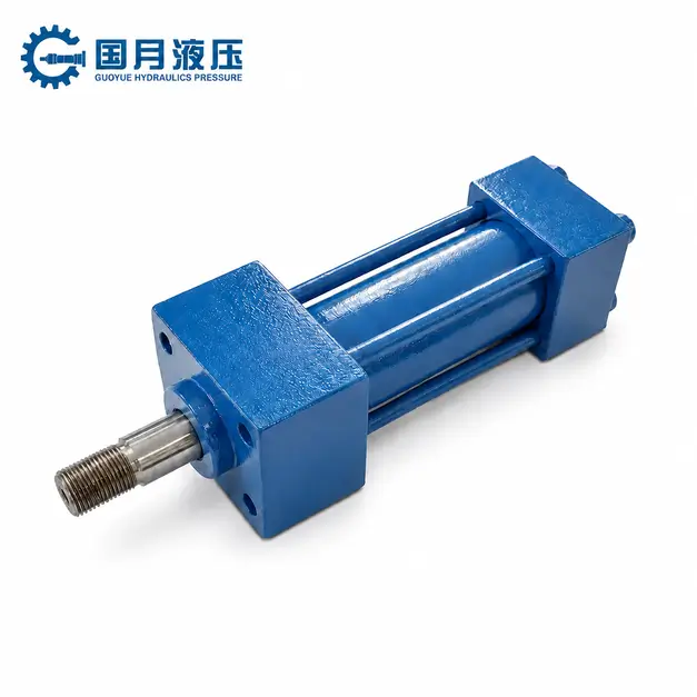
Based on their structure and piston rod configuration, common double-acting hydraulic cylinders primarily include tie-rod, welded, mill-duty, threaded, single-rod, and double-rod types; some telescoping hydraulic cylinders may also feature a double-acting design.
a. Tie-Rod, Welded, Mill-Duty, and Threaded Designs
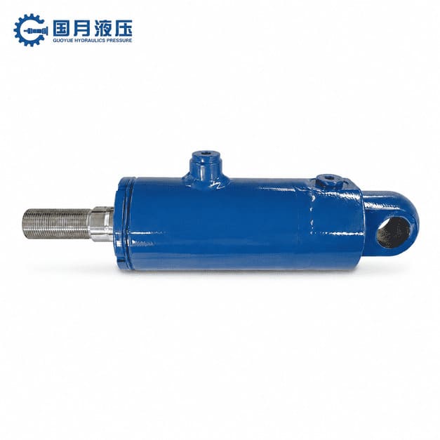
| Type | Simple Explanation | Key Features | Best Suited For |
|---|---|---|---|
| Tie-Rod | The cylinder barrel and end caps are secured together with external tie rods. | Easy to install, disassemble, and maintain. | Industrial equipment and automation equipment. |
| Welded | The cylinder base or mounting components are directly welded to the cylinder barrel. | Compact structure with no external tie rods. | Construction machinery, agricultural machinery, and mobile equipment. |
| Mill-Duty | Designed for heavy loads and high-frequency operation. | Robust construction for demanding industrial environments. | Steel mills, mining equipment, presses, and large industrial machinery. |
| Threaded | Main cylinder components are connected using threaded joints. | Compact structure and flexible design. | Space-limited installations and specific equipment designs. |
Tie-rod cylinders are generally easy to disassemble and service, although the external tie rods increase the installation envelope.
Welded cylinders typically provide a more compact package and are widely suited to mobile equipment, but their serviceability depends on the actual head and end-cap construction.
Mill-duty cylinders are selected primarily around shock loading, duty cycle, fatigue resistance, mounting conditions, and maintenance requirements rather than a universal pressure or life rating.
Threaded cylinders can also provide a compact structure, but the threaded connections should be evaluated for locking, fatigue, disassembly, and future servicing. In all cases, pressure capability, fatigue life, and maintainability depend on the specific cylinder design rather than the construction type alone.
b. Single-Rod Versus Double-Rod Configurations
- A single-rod cylinder has a piston rod on one side only, so its effective areas differ between extension and retraction. As a result, force and speed are typically different in the two directions, making this configuration suitable for most pushing, pulling, lifting, and clamping applications.
- A double-rod cylinder has piston rods on both sides. When both rods have the same diameter, the geometric effective areas on each side are equal, so the theoretical force and speed in both directions are more similar. However, actual bidirectional performance can still vary because of pressure differences, backpressure, friction, external loads, and hydraulic circuit conditions.
For general applications, single-rod cylinders are usually the simpler choice; double-rod cylinders are worth considering when more balanced bidirectional motion is required.
c. Cushioned, Position-Sensing, and Servo-Ready Options
Cushioned cylinders reduce end-of-stroke impact by decelerating the piston near the end position, but the cushion design must be matched to the moving mass, speed, end-of-stroke pressure, and allowable deceleration. Position-sensing cylinders use actual feedback devices—such as magnetostrictive, linear displacement, or external sensors—to detect piston or rod position. For higher-precision position, speed, or force control, a hydraulic cylinder may be integrated into a servo system, which typically also requires suitable mechanical stiffness, low-friction sealing, position feedback, a proportional or servo valve, and a controller. “Servo-ready” should therefore not be treated as a universal standard cylinder feature unless the manufacturer defines a specific servo-ready design and configuration.
How Should You Choose?
For an automated clamping application, start with the actual operating requirements: clamping force, release force, stroke, available pressure, cycle frequency, speed, mounting method, installation space, end-of-stroke impact, and any pressure-loss holding requirement. A double-acting, single-rod cylinder is often suitable when both clamping and release require active control and higher force is needed mainly in the clamping direction. If space is limited, compare welded and compact tie-rod designs based on envelope size, maintenance access, pressure capability, duty cycle, and manufacturability rather than choosing by construction type alone. Cushioning can reduce end-of-stroke impact, while position feedback can confirm clamp or release position without requiring a complete servo system.
GY Project Reference:
In a German steel mill AGC application, GY Hydraulic supplied a cylinder with a 320 mm bore, 220 mm piston rod, 900 mm stroke, and 250 bar working pressure for continuous 24-hour operation. The design used an upgraded sealing system and hardened piston-rod surface treatment. Validation included a 500 bar static pressure test, 10,000-cycle test, pressure-holding test, internal-leakage test, dimensional inspection, and coaxiality inspection. According to GY Hydraulic’s project record, service life increased from approximately 6 months to approximately 12 months. Although this is not a clamping application, it shows why cylinder selection should be based on real load, pressure, duty cycle, sealing, materials, and validation requirements rather than bore and stroke alone.
What Are the Advantages and Limitations?
The biggest advantage of double-acting hydraulic cylinders is that both extension and retraction are actively controlled by hydraulic pressure, making them suitable for equipment that requires frequent reciprocating motion, bidirectional force, and stable movement. However, their hydraulic circuits are more complex, and their cost and maintenance requirements are typically higher than those of single-acting hydraulic cylinders.
Key Advantages
A double-acting hydraulic cylinder can generate force during both extension and retraction, so the return stroke does not need to rely on gravity, springs, or an external load. This makes bidirectional motion easier to control through directional valves and flow-control devices, although actual control accuracy still depends on the hydraulic circuit, load variation, and any feedback system used. Double-acting cylinders are well suited to repeated pushing, pulling, lifting, clamping, and positioning tasks, but smooth and stable motion still requires proper oil cleanliness, air removal, suitable flow control, and appropriate load conditions. Optional features such as end-of-stroke cushioning, position sensors, proportional control, or servo control can be added when the application requires higher levels of motion management; these functions are not standard on every double-acting cylinder.
Main Limitations
Double-acting hydraulic cylinders typically require two working ports, bidirectional piping, and directional control valves; therefore, their hydraulic circuits and installation layouts may be more complex than those of simple single-acting systems, and the initial system cost may also be higher. Actual cost differences depend on cylinder bore, rod diameter, stroke, pressure rating, materials, mounting method, valve assemblies, piping, customization requirements, and purchase quantity; it is not recommended to use fixed percentages or price ranges that lack uniform comparison criteria. For common single-rod double-acting hydraulic cylinders, because the effective area on the retraction side is smaller, the retraction force is typically lower than the extension force at the same pressure; therefore, the load-carrying capacity in both directions must be verified separately. At the same time, the greater number of hoses, fittings, and control components means there are more potential leak points to inspect. System energy consumption cannot be determined solely based on whether the cylinder is “single-acting” or “double-acting”; it also depends on the pump control method, throttling losses, load cycles, operating pressure, and the efficiency of the entire hydraulic circuit.
When Is It More Appropriate to Use?
If your equipment requires active extension and retraction, frequent reciprocating motion, bidirectional load-bearing, or stable speed control, a double-acting hydraulic cylinder is more suitable. For example, excavator booms, industrial automation feed mechanisms, or hydraulic clamping fixtures—which require the cylinder to actively extend and retract while operating in repeated cycles—typically call for double-acting hydraulic cylinders.
If the application involves simple lifting, clamping, or unidirectional operation, and the return stroke is stable, a single-acting design is usually simpler and more cost-effective. For example, manual hydraulic jacks or certain lifting platforms that only require the cylinder to lift upward—with the load’s gravity handling the descent—should prioritize single-acting hydraulic cylinders.
Don’t automatically assume that double-acting hydraulic cylinders are better simply because they offer greater control capabilities. You should first confirm whether the equipment truly requires bidirectional hydraulic power before deciding whether it’s worth the additional cost of valves, piping, and maintenance.
Where Are Double-Acting Cylinders Used?
Double-acting hydraulic cylinders are suitable for equipment requiring active extension and retraction, frequent reciprocating motion, or bidirectional force output. The key considerations for selection vary depending on the application:
- Construction Machinery: Commonly used in the booms, dippers, and other actuators of equipment such as excavators and loaders; Key considerations include impact loads, alignment of pins and mounting points, dust contamination, piston rod surface protection, hose tracking, and cycle frequency.
- Industrial Automation: Used in feeding, positioning, clamping, and reciprocating mechanisms; focus should be on duty cycles, positional repeatability, low-speed operational stability, end-of-stroke cushioning, position sensors, and load-holding requirements after pressure loss.
- Agricultural Machinery: Used in tilting, lifting, adjusting, and folding mechanisms; priority should be given to evaluating mud and water contamination, corrosion, ambient temperature fluctuations, long-term outdoor storage, and hose routing and protection.
- Material Handling Equipment: Used in forklifts, lifting devices, and tilting, pushing, and pulling mechanisms; Consideration should be given to vertical loads, rollover risks, load retention, lateral loads, and abnormal operating conditions such as hose rupture.
- Hydraulic Clamping Systems: Used for workpiece clamping and active release; separate verification is required for clamping force, release force, pressure hold time, internal leakage, cycle frequency, and whether mechanical locking or other safety retention measures are required.
- Presses and Forming Equipment: Used for main working strokes and active return strokes; special attention should be given to thrust force, return force, guidance and alignment, pressure peaks, and fatigue life under high-cycle conditions.
The above represent typical engineering selection considerations. Specific hydraulic cylinder specifications should still be verified based on actual loads, bore diameter, rod diameter, stroke, operating pressure, mounting method, environmental conditions, and the hydraulic circuit.
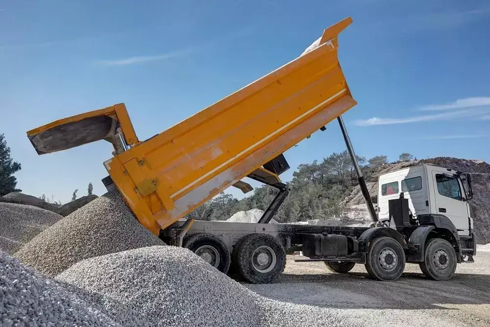
When Should They Be Used?
If your equipment requires a hydraulic cylinder to actively perform work in both the extension and retraction directions, or if it requires frequent reciprocating motion, stable speed control, and the ability to withstand bidirectional loads, choose a double-acting hydraulic cylinder.
When selecting a model, you should first consider the operational requirements. For example, the dipper arm of an excavator must actively extend and retract, and it must bear loads in both directions; such operating conditions are better suited for double-acting hydraulic cylinders. In contrast, some jacks only require hydraulic lifting, and can rely on the load’s own weight to return during lowering, so there is no need to use a double-acting design.
Therefore, when determining whether a double-acting hydraulic cylinder is needed, focus on four key points: whether bidirectional power is required, the return mechanism, the operating frequency, and the direction of the load.
Double-Acting vs Single-Acting: Which Fits the Application?
Single-acting hydraulic cylinders are better suited for applications with simple structures that rely primarily on hydraulic pressure in a single direction; their return stroke can be achieved by gravity, springs, or external loads. Double-acting hydraulic cylinders, on the other hand, are better suited for operating conditions that require active bidirectional control, frequent reciprocating motion, and high cycle efficiency. It is important to note that single-acting hydraulic cylinders are not inherently “fail-safe”: even if designed to move in a specific direction upon pressure loss, gravity, spring force, internal leakage, or valve leakage may still cause unintended motion. Therefore, the actual behavior after pressure loss should be assessed in conjunction with the overall machine structure and the complete hydraulic circuit to evaluate risks.
Compare Return Method, Control, Energy Use, Cost, and Safety
| Comparison Item | Single-Acting Hydraulic Cylinder | Double-Acting Hydraulic Cylinder |
|---|---|---|
| Return Method | Returns via gravity, springs, or an external load. | Returns actively using hydraulic pressure. |
| Bidirectional Control | Limited; the return movement mainly depends on an external force. | Extension and retraction can both be actively controlled. |
| System Complexity | Piping and control are typically simpler. | Typically requires two working ports, bidirectional hydraulic lines, and directional control. |
| Energy Usage | The return stroke may not require hydraulic power, depending on the load and return method. | Total energy use depends on the duty cycle, pump control method, operating pressure, flow rate, and throttling losses; a double-acting system is not inherently less efficient or more energy-intensive. |
| Cost | Typically lower for simple applications with fewer hydraulic components. | Initial system cost may be higher because additional valves, lines, fittings, and controls can be required. |
| Load Holding and Safety | After pressure loss, the cylinder may move under gravity, spring force, or external load and should not be assumed to be automatically fail-safe. | Both directions can be hydraulically controlled, but seal or valve leakage may still cause drift. Vertical or suspended loads typically require load-holding valves, mechanical locking, or another dedicated safety measure. |
| Suitable Operating Conditions | Simple unidirectional work where the return stroke can be reliably provided by gravity, a spring, or an external load. | Applications requiring active bidirectional control, frequent reciprocating motion, or force in both directions. |
Decision Rules for Vertical, Horizontal, and Repetitive Motion
- Vertical Motion: If the hydraulic cylinder only needs to actively lift the load and the descent can be reliably accomplished by gravity, a single-acting hydraulic cylinder may be considered; if both lifting and lowering require active control, a double-acting hydraulic cylinder is typically more suitable. However, the ability to rely on gravity for descent does not automatically mean the descent process is inherently safe; risks related to descent speed control, hose rupture, valve leakage, power outages, and maintenance conditions must also be verified.
- Horizontal Motion: If both pushing and retracting require active force, double-acting hydraulic cylinders are generally preferred, as horizontal motion typically cannot rely on gravity to achieve a stable return stroke.
- Frequent Reciprocating Motion: For equipment requiring frequent bidirectional motion—such as continuous pushing, pulling, clamping, feeding, or positioning—double-acting hydraulic cylinders are generally more suitable; for low-frequency, unidirectional operations where the return stroke can be reliably accomplished by gravity, springs, or external loads, single-acting hydraulic cylinders may be considered.
Simple decision-making principle: If the return stroke also requires active hydraulic force, double-acting hydraulic cylinders are generally the preferred choice; if the return stroke can be reliably accomplished by gravity, springs, or external loads, single-acting hydraulic cylinders may be considered. For example, traditional hydraulic jacks primarily rely on hydraulic pressure for lifting and lower the load through controlled pressure relief, so they often use a single-acting design; in contrast, automated horizontal feeding mechanisms typically require active pushing and active pulling, making a double-acting design more suitable.
It is important to note that the type of hydraulic cylinder alone does not determine whether a piece of equipment is safe. For equipment handling vertical loads, suspended loads, or posing risks to personnel, the need for load holding, mechanical locking, or other safety measures must be determined by considering the complete mechanical structure, hydraulic circuit, pressure loss conditions, and risk assessment—conclusions cannot be drawn based solely on whether the cylinder is “single-acting” or “double-acting.”
How Do You Size and Specify a Double-Acting Cylinder?
When specifying a double-acting hydraulic cylinder, you must at least determine the bore, rod diameter, stroke, operating pressure, and required thrust and pull forces. You should then consider the mounting configuration, speed, lateral loads, cushioning, and operating environment.
Bore, Rod Diameter, Stroke, Pressure, and Force Calculations
1. Bore
The bore determines the piston’s effective area and is the key parameter affecting the extension thrust. Theoretical extension force: Fextend = P × Ap. Where:
- F = Output force
- P = Hydraulic pressure
- Ap = Piston area
Piston area: Ap = π × D² ÷ 4. The larger the bore, the greater the theoretical thrust that can be generated at the same pressure.
2. Rod Diameter
The rod diameter affects structural strength as well as the retracting force. Theoretical retracting force: Fretract = P × (Ap – Ar). Where:
- Ap = Piston area
- Ar = Piston rod cross-sectional area
Therefore, for a single-rod, double-acting hydraulic cylinder operating at the same pressure, the extension force is typically greater than the retraction force. If the return stroke also requires pulling a heavy load, you must verify separately whether the retraction force is sufficient. For long strokes or under heavy compressive loads, you must also check the piston rod’s resistance to bending and buckling; the rod diameter should not be selected based solely on tensile force.
3. Stroke
Stroke refers to the distance the piston rod travels from fully retracted to fully extended. You should select the stroke based on the actual travel distance required by the equipment. An excessively long stroke not only increases the installation space but may also increase the risk of piston rod bending and lateral loading.
4. Working Pressure
The working pressure must be compatible with the equipment’s hydraulic system. When calculating the output force, use the equipment’s actual working pressure rather than the hydraulic cylinder’s maximum allowable pressure. Actual output force is also affected by friction, sealing resistance, and system pressure losses; therefore, it is generally recommended to allow for a thrust margin of approximately 10% to 20% during selection. If there are significant impacts, frequent starts and stops, low temperatures, high friction, or load fluctuations, it is recommended to increase the margin to 20% to 30%.
Mounting, Speed, Cushioning, Side Load, and Environment
Once the bore diameter, rod diameter, and stroke of the hydraulic cylinder have been determined, the following factors should also be examined in light of the actual operating conditions of the equipment:
- Mounting Method: Confirm the type of mounting—such as flanges, trunnions, pins, eyes, or other configurations—and check for any risk of mounting eccentricity, misalignment, or jamming during operation. The hydraulic cylinder should be subjected to axial forces as much as possible, and the mounting structure itself should allow for normal oscillation or realignment.
- Operating Speed: The speed of a hydraulic cylinder primarily depends on the flow rate entering the working chamber and the effective area; however, theoretical speeds alone should not be relied upon. It is also necessary to confirm that the required flow rate falls within the capacity of the pump, valves, ports, and piping, and to check whether pressure drops at the ports, piping losses, and return line back pressure might limit the actual speed or reduce the effective output force.
- Cushioning: The need for cushioning should not be determined solely based on “high speed”; it should be determined comprehensively by considering mass, operating speed, end-of-stroke pressure, and the deceleration and impact levels permitted by the equipment. If the cushioning design is inappropriate, excessive end-of-stroke impact or insufficient deceleration distance may occur.
- Side Load: Hydraulic cylinders are primarily designed to withstand axial thrust and tension and should not be subjected to significant lateral forces or eccentric loads over extended periods. Continuous side loading may accelerate wear on guide sleeves, wear rings, seals, and the piston rod; therefore, external guide rails, sliders, or mechanical guide structures should be used whenever possible to bear lateral loads.
- Operating Environment: Temperature ranges, hydraulic fluids, corrosive environments, dust, moisture, and outdoor exposure conditions all influence the selection of materials for hydraulic cylinders. In actual design, these conditions should be addressed in terms of seal materials, dust-proof/dust-wiping mechanisms, piston rod surface treatments, cylinder body corrosion protection, and lubrication compatibility, rather than simply noting “outdoor use” or “high-temperature use.”
- Contamination & Fluid Cleanliness: Fluid contamination directly affects the service life of valves, seals, and internal cylinder components. If the equipment has specific cleanliness requirements, the target grade should be specified according to the actual system specifications. **ISO 4406:2021 primarily provides a coding method for particle contamination levels in hydraulic fluids; it does not automatically prescribe a universal target cleanliness grade for all hydraulic systems. ** Therefore, it is not recommended to specify a uniform ISO 4406 target value in the absence of customer specifications, valve requirements, or company design standards.
The final selection of a hydraulic cylinder should be based on a verification of these operating conditions in conjunction with load, pressure, speed, cycle frequency, and maintenance practices; selection should not be based solely on cylinder bore and stroke.
Information to Include in an RFQ
To improve the accuracy of hydraulic cylinder selection and quoting, we recommend providing as complete a set of information as possible regarding load, dimensions, the hydraulic system, and operating conditions. If some parameters have not yet been determined, you may first provide the equipment requirements so that the supplier can perform preliminary calculations and structural evaluations.
We recommend providing:
- Bore
- Rod Diameter
- Stroke
- Normal operating pressure and maximum operating pressure
- Pressure measurement location, and whether there is likely to be significant back pressure on the return line
- Normal load and maximum load
- Thrust required for extension and tensile force required for retraction
- Load direction, and whether the hydraulic cylinder will primarily operate in a pushing or pulling condition
- Extension speed and retraction speed
- Mounting method and key mounting dimensions
- Available installation space
- Whether external guide rails or other mechanical guidance structures are required
- Port specifications, locations, and orientations
- Whether end-of-stroke cushioning is required
- Working fluid and hydraulic oil requirements
- Minimum and maximum operating temperatures
- Operating environment (e.g., dust, moisture, corrosion, outdoor conditions)
- Whether lateral loads, off-center loads, or impact loads are present
- Whether a position sensor is required
- Permissible stopping position accuracy and position drift requirements
- Number of cycles per minute, hour, or day
- Expected service life or target total number of cycles
- Whether the hydraulic cylinder should maintain its current position, retract, or release upon pressure loss
- Acceptance test requirements, such as pressure resistance, pressure hold, internal and external leakage, stroke, or functional tests
- Required documentation, such as dimensional drawings, material certificates, inspection records, or test reports
- Applicable regulations, industry standards, or customer-specified standards
- Equipment drawings, installation diagrams, drawings of existing hydraulic cylinders, or old models
If the specific cylinder bore and piston rod diameter are not yet known, you may first provide normal/maximum load, required thrust or pull force, actual system operating pressure, stroke, speed, installation space, mounting method, and cycle frequency. Suppliers can use this information to perform theoretical stress calculations and further determine the cylinder bore, rod diameter, mounting structure, and sealing solution.
For custom hydraulic cylinders, a more comprehensive technical validation process should typically be followed:
Customer operating conditions → Theoretical calculations → Structural selection → Risk verification → Prototype or functional testing → Final specification confirmation
If the project has specific requirements for acceptance and functional testing, the corresponding test items can be agreed upon during the technical agreement phase, and test methods and documentation requirements can be determined by referring to applicable standards (e.g., ISO 10100:2020). Unless there are actual test records, the statement “The product has been tested in accordance with ISO 10100” should not be included.
What Common Failures Should Buyers Plan For?
When purchasing double-acting hydraulic cylinders, the most important failures to consider in advance include seal leakage, cylinder drift, scoring of the piston rod or cylinder barrel, fluid contamination, and piston rod buckling.
Seal Leakage, Drift, Scoring, Contamination, and Buckling
| Common Failures | Symptoms You Might Observe | Possible Causes | Recommended Diagnosis |
|---|---|---|---|
| Seal Leakage | Oil appears around the piston rod, external leakage increases, or the cylinder cannot maintain pressure as expected. | Seal wear or damage, piston rod scoring, pressure spikes, contamination, or incompatibility between the seal material, hydraulic fluid, and operating temperature. | Inspect the rod surface, seal condition, fluid type, operating temperature, and actual pressure history. Check for pressure spikes and contamination before replacing seals alone. |
| Cylinder Drift | The piston rod moves slowly after the control command stops or while a load is being held. | Internal leakage across the piston seal, directional valve leakage, load-holding valve leakage, fitting or connection leakage, or other hydraulic circuit losses. | Isolate and test the cylinder and hydraulic circuit separately where practical. Check piston-seal leakage, directional valves, load-holding components, connections, and pressure decay before identifying the cylinder as the root cause. |
| Scoring | Scratches, grooves, or abnormal wear appear on the piston rod or cylinder bore, sometimes accompanied by leakage or rough movement. | Contaminant particles, misalignment, insufficient guidance, sustained side loads, failed rod wipers, or damaged rod and bearing surfaces. | Check installation alignment, external guidance, wear rings or guide components, rod-wiper condition, fluid cleanliness, and surface damage. Correct side loading rather than treating surface damage alone. |
| Fluid Contamination | Wear increases, valves or seals may behave inconsistently, and cylinder movement can become less predictable over time. | Contaminated hydraulic fluid, ineffective filtration, moisture or particles entering through the system, or insufficient internal cleanliness of components during manufacturing or assembly. | Distinguish system-fluid cleanliness from component internal cleanliness. Check filtration, oil condition, tank and hose cleanliness, wiper protection, and the cleanliness requirements applied during cylinder manufacturing and assembly. |
| Piston Rod Buckling | The piston rod bends, binds, vibrates, or moves abnormally under compressive load. | Insufficient rod diameter, excessive unsupported length, unfavorable mounting conditions, eccentric loading, side loads, or compressive force above the design condition. | Verify rod diameter, stroke, actual mounting configuration, effective buckling length, alignment, maximum compressive load, eccentricity, and any external side load. |
| Slow Movement | Extension or retraction is slower than expected, inconsistent, or unable to reach the required cycle time. | Insufficient flow, blocked filters, pump suction problems, air entering the system, high oil viscosity at low temperature, excessive return backpressure, valve restrictions, or incorrect cylinder sizing. | Measure actual flow, pressure differential, return pressure, and oil temperature. Check for air ingress and filter restriction, then verify the relationship between required speed, flow, and effective cylinder area. Do not increase relief-valve pressure blindly. |
| Cushion Failure | Excessive impact occurs near the end of the stroke, or the piston decelerates too early, too late, or inconsistently. | Incorrect cushion adjustment, damaged cushion components, excessive moving mass or speed, abnormal end-of-stroke pressure, or unexpected backpressure. | Record end-of-stroke speed and pressure behavior, inspect the cushion needle or internal cushion components, and recheck whether the cushion capacity matches the moving mass, speed, and required deceleration. |
Inspection and Preventive Maintenance Checkpoints
- Piston rod surface: Check for scratches, rust, bending, or abnormal wear.
- Seals and rod end positions: Check for oil leaks or oil accumulation.
- Hoses and fittings: Check for looseness, leaks, wear, and line interference.
- Mounting pins and connection points: Check for looseness, misalignment, and abnormal clearance.
- Hydraulic fluid: Monitor for contamination, moisture, and noticeable discoloration, and maintain the filtration system according to equipment specifications.
- Operational behavior: If crawling, juddering, abnormal speed, or inability to hold position occurs, inspect immediately rather than continuing to increase system pressure.
When preventing failures, I strongly recommend prioritizing the following three issues: keeping the fluid clean, avoiding lateral loads, and selecting the correct piston rod size. These three factors often directly affect the service life of seals, guide components, piston rods, and cylinder barrels.
When purchasing, you should also specify to the supplier the load direction, maximum thrust and tensile force, stroke, mounting method, operating frequency, environment, and whether lateral forces are present. For example, if a hydraulic cylinder needs to push a 10-metric-ton load, the piston rod is subjected to compressive force during extension, the stroke is 500 mm, and the equipment is subject to slight lateral forces, you should explain these specific operating conditions to the supplier and provide details on the mounting method, operating frequency, and operating environment. Otherwise, even if the hydraulic cylinder has a sufficient pressure rating, the piston rod may experience premature bending, seal wear, or operational jamming due to an excessively small rod diameter, an excessively long stroke, or eccentric mounting.
Double Acting Hydraulic Cylinder:FAQs
Q1: Can a Double-Acting Cylinder Hold a Load if Pressure Is Lost?
No. If system pressure is lost, internal leakage or control valve leakage may cause the piston to move. For vertical or suspended loads, a hydraulically controlled check valve, balancing valve, mechanical locking device, or other reliable load-holding measure must be installed.
Q2: Does a Double-Acting Cylinder Produce Equal Force in Both Directions?
A standard single-rod double-acting hydraulic cylinder does not produce equal force in both directions. Because the piston rod occupies part of the pressure-receiving area on the retraction side, the extension force is typically greater than the retraction force at the same pressure. Only in special designs where the effective areas on both sides are identical or nearly identical can the forces in both directions be approximately equal.
Q3: Can a Double-Acting Cylinder Be Used as a Single-Acting Cylinder?
Yes, but it is not recommended to simply block one port. If pressure is supplied to only one side, the other side must be able to properly drain or vent; otherwise, back pressure will build up, affecting movement and potentially damaging the seals. Whether this configuration is feasible depends on the cylinder’s design, the retraction method, and the circuit design.
Q4: Which Valve Is Required for a Double-Acting Cylinder?
A directional control valve capable of controlling the flow direction at both ports is required. A common choice is a 4-way directional control valve, which directs pressurized fluid into either the rodless chamber or the rod chamber to achieve extension and retraction. The specific choice between a 4/2, 4/3, or other valve type depends on whether center position, load holding, and circuit functions are required.
Work with a IATF 16949 Certified Blind Rivet Manufacturer
Get High Quality Rivets Instead of Huck and Avdel Rivets
Explore Rivmate Cases

Hey There, I'm Melody!
We are a hydraulic cylinder manufacturer. For over 20 years, we have focused on producing reliable hydraulic cylinders. Need a hydraulic cylinder solution? Feel free to contact us.